Ed Nisley's Blog: Shop notes, electronics, firmware, machinery, 3D printing, laser cuttery, and curiosities. Contents: 100% human thinking, 0% AI slop.
Red Oaks Mill Intersection – close pass – approach – 2020-12-24
Most drivers seem content to wait behind us until we get into the huge intersection where there’s plenty of room (comparatively speaking) to pass, but not this one:
Red Oaks Mill Intersection – close pass – waiting – 2020-12-24
I warned Mary (one the reasons we have radios on our bikes) about the mirror just behind her shoulder and she verified the minimal clearance:
Red Oaks Mill Intersection – close pass – arms length – 2020-12-24
Prudence dictated we wait until he was clear before moving:
Red Oaks Mill Intersection – close pass – rolling – 2020-12-24
Of course, the signal timing doesn’t let us get all the way through the intersection under the best of conditions, but we make an impressive enough parade to keep oncoming cars from moving before we’re out of their way.
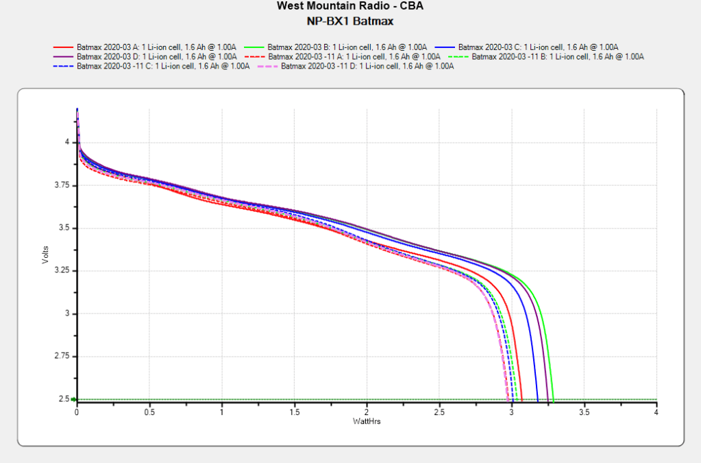
After powering my Sony HDR-AS30V helmet camera for nearly all of this year’s riding, the Batmax NP-BX1 lithium batteries still have roughly 90% of their original capacity:
Batmax NP-BX1 – 2020-11
Those are hot off the Official Batmax charger, which appears identical to other randomly named chargers available on Amazon.
They’re holding up much better after a riding season than the DOT-01 batteries I used two years ago:
Sony DOT-01 NP-BX1 – 2019-10-29
Empirically, they power the camera for about 75 minutes, barely enough for our typical rides. I should top off the battery sitting in the camera unused for a few days, although that hasn’t happened yet.
Of course, the Batmax NP-BX1 batteries I might order early next year for the new riding season have little relation to the ones you see here.
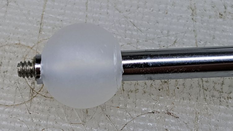
The stiffness of the bike helmet mirror mount suggested a similar clamp would have enough griptivity to immobilize the ball while cutting it in the lathe:
Helmet Mirror Mount – 10 mm ball
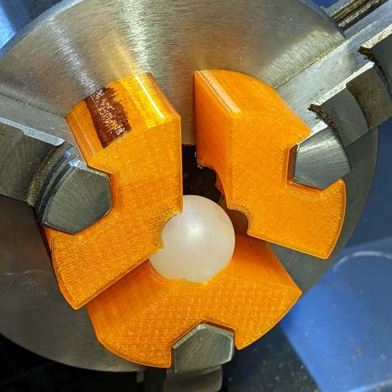
Building the clamp around the lathe’s three-jaw lathe chuck eliminates the need for screws / washers / inserts:
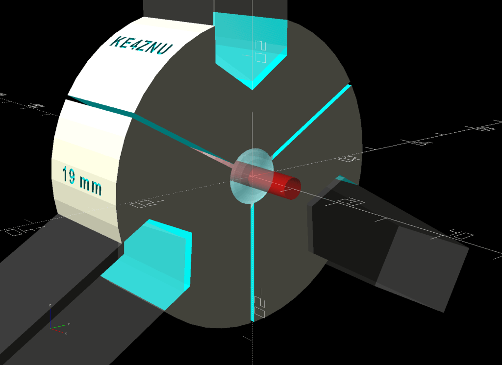
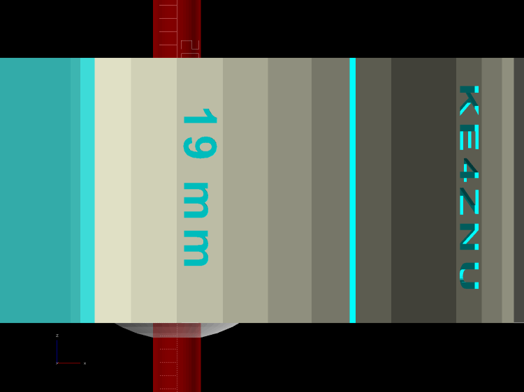
Lathe Ball Fixture – 19 mm – Show
The Ah-ha! moment came when I realized the fixture can expose half of the ball’s diameter for drilling while clamping 87% of its diameter, because 0.5 = sin 30° and 0.87 = cos 30°:
Lathe Ball Fixture – 19 mm – Show – front orthogonal
That’s an orthogonal view showing 13% of the ball radius sticking out of the fixture; it’s 6% of the diameter.
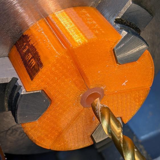
Which looks like this in real life:
Lathe Ball Fixture – 19 mm – sections with ball
The socket is offset toward the tailstock end of the clamp (on the right in the picture) to expose half its diameter flush with the surface perpendicular to the lathe axis. The other side necks down into a cylinder of the same diameter to clear the drill bit.
This works nicely until the ball diameter equals the chuck jaw’s 20 mm length, whereupon larger balls protrude into the chuck body’s spindle opening. Although I haven’t yet built one, the 25 mm balls in my Box o’ Bearings should fit, with exceedingly sissy cuts required for large holes.
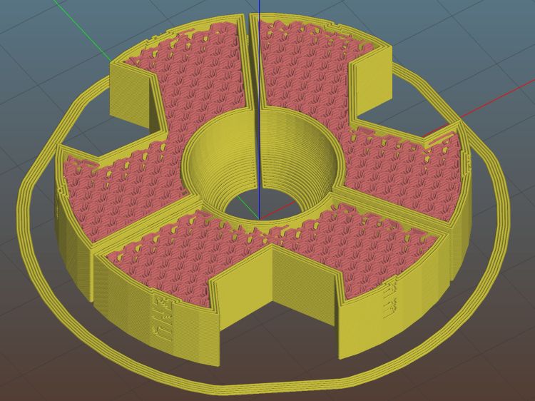
The fixture doesn’t require support material, because the axial holes eliminate the worst of the overhang. Putting the tailstock side flat on the platform gives it the best-looking surface:
Lathe Ball Fixture – 19 mm – Slic3r – equator
The kerf between the segments ensures the jaws can apply pressure to the ball, whereupon the usual crappy serrated 3D printed surface firmly grabs it.
The fixture is a slip fit on the chuck jaws:
Lathe Ball Fixture – 19 mm – installed
Tightening the jaws shoves them all the way into the fixture’s slots and clamps the ball:
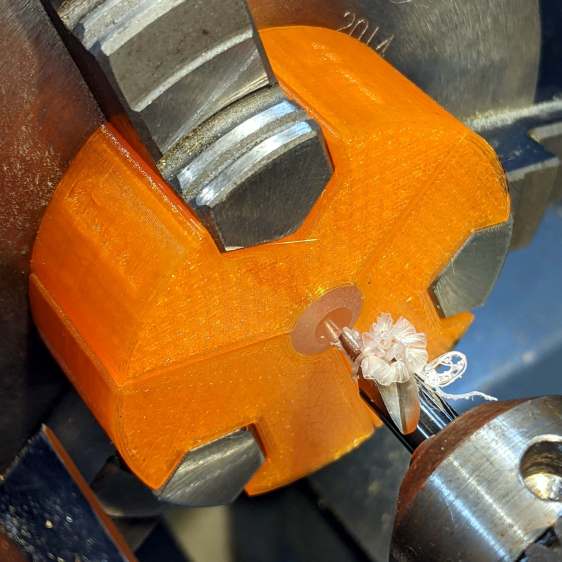
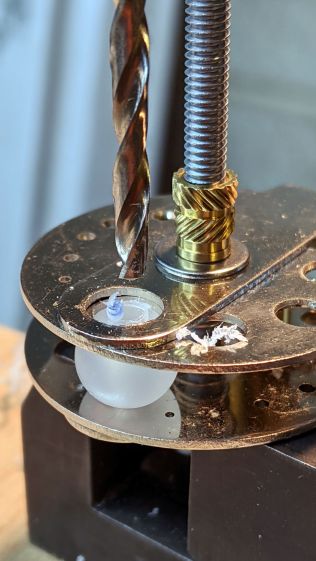
Lathe Ball Fixture – 19 mm – center drill
Overtightening the chuck will (probably) compress the ball around the drill, which will (best case) give you slightly oversize holes or (worst case) cause the ball to seize / melt around the drill bit, so sleaze up to the correct hole diameter maybe half a millimeter at a time:
Lathe Ball Fixture – 19 mm – 6 mm drill
That fixture exposes 9.5 mm = 19/2 of the ball. The drill makes a 6 mm hole to fit the telescoping shaft seen above.
Obviously, you must build a custom fixture for every ball diameter in your inventory, which is no big deal when you have a hands-off manufacturing process. Embossing the diameter into the fixture helps match them, although the scribbled Sharpie isn’t particularly elegant.
This file contains hidden or bidirectional Unicode text that may be interpreted or compiled differently than what appears below. To review, open the file in an editor that reveals hidden Unicode characters.
Learn more about bidirectional Unicode characters
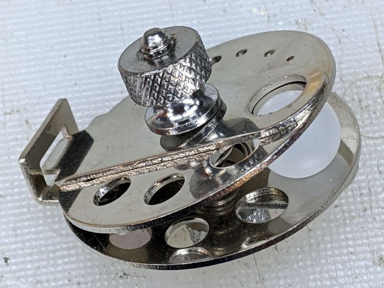
Given the angle between the two plates, I didn’t see any way to put a large hole though the center of the ball:
Micromark Ball Vise – 10 mm ball
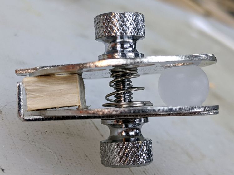
A scrap of wood aligned the two plates somewhat better:
Micromark Ball Vise – wood block
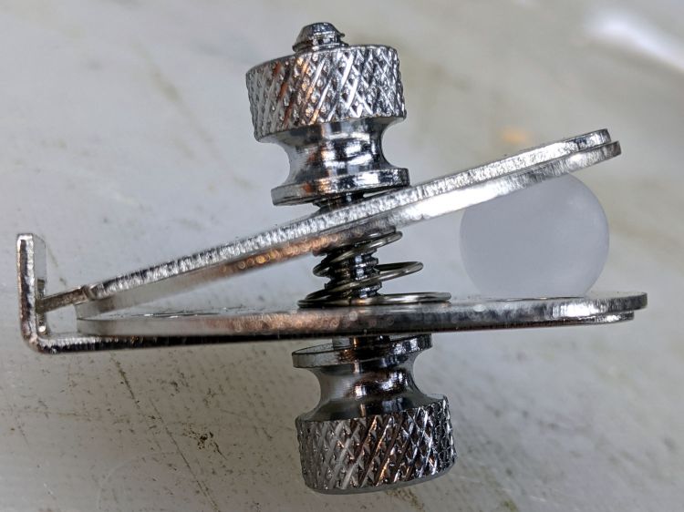
With that as a hint, the Box o’ Brass Cutoffs disgorged a better spacer, although the original screw was just an itsy too short:
Micromark Ball Vise – brass tube
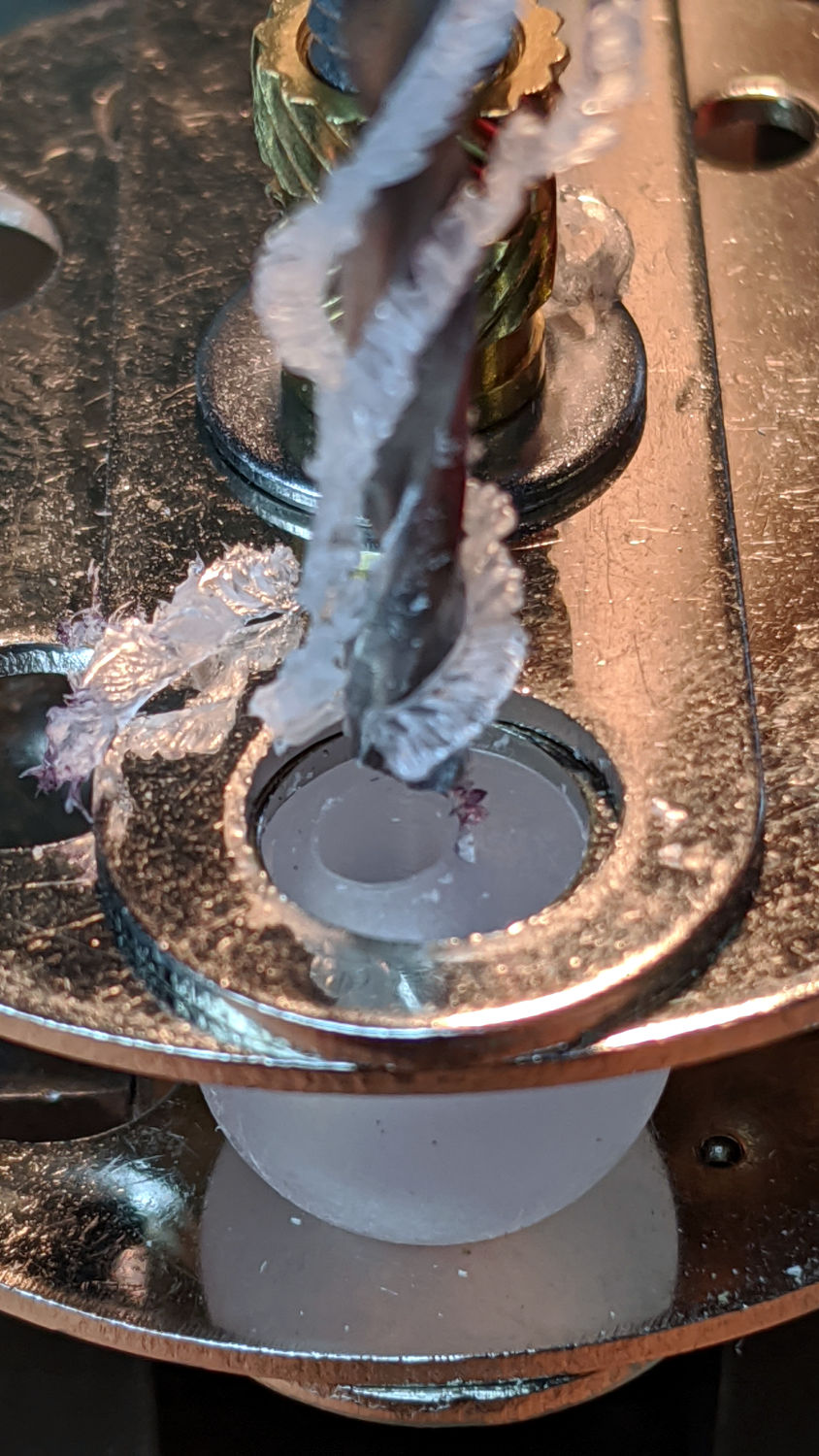
Grabbing the modified vise in a machinist’s vise got me most of the way toward the goal:
Micromark Ball Vise – drill press
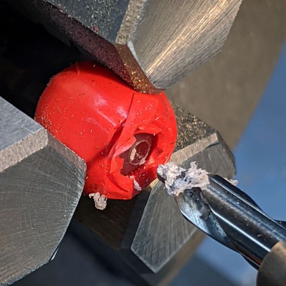
Polypropylene is grabby, so the drill stuck / rotated the ball inside the vise / made a mess:
Micromark Ball Vise – offset hole
A close look at the top picture shows the nasty ring around the hole (on the right side). The vise grips the ball between two holes punched in the metal plates, contacting it only at the right-angle (-ish) edges forming two rings, so there’s really not enough friction against the plastic to hold the ball in position and any slippage results in a gouge. Perhaps pearls / beads / jewelry behave differently?
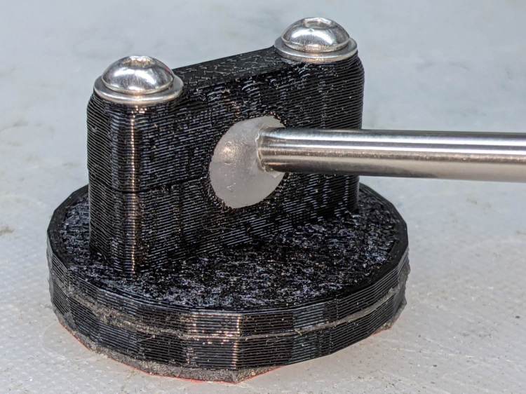
Fortunately, I had a bag of 100 balls, so a few failures gave me enough of a clue to do what I should have done from the beginning:
Micromark Ball Vise – lathe ball hack
That’s silicone tape wrapped around a ball grabbed in the lathe chuck, with a center drill in the tailstock. There’s barely enough traction between the ball and the chuck to get the job done, but it worked out well enough to build a few new mirrors:
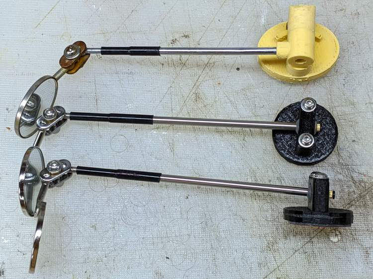
Helmet Mirror Ball Mount – new vs old
There’s obviously a better way, although it took a few weeks to shake out the solid model …
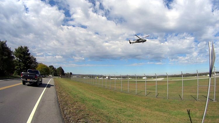
The same helicopter thumped over our house, about two miles from the runway as the chopper flies, while I was getting ready for the ride, and it was hovering as I reached the airport. I think the pilot was practicing, because the chopper made very precise movements across the airport, translated front / back / left / right, and hovered motionless for minutes at a time despite wind gusts.