Ed Nisley's Blog: Shop notes, electronics, firmware, machinery, 3D printing, laser cuttery, and curiosities. Contents: 100% human thinking, 0% AI slop.
The front fender on Mary’s bike suffers a bit more stress than you might expect, as she must wheel it through high grass to her Vassar Farms garden plot and the low-hanging spray flap can snag on the taller greenery.
Re-slicing the original model, printing the result, and installing it took about an hour:
Tour Easy front fender bracket – installed
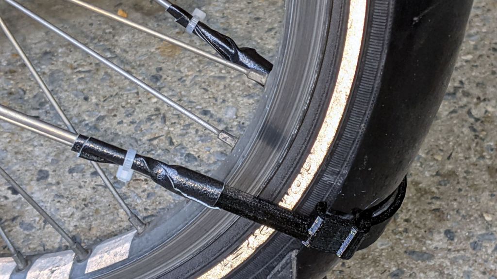
Affixing the strut with duct tape and a cable tie looks déclassé, but continues to work better than anything else I’ve tried: simple, flexible, easily readjusted, totally nonfussy.
At least I now use black outdoor-rated double-stick foam tape, so life is increasingly good …
All the work on Mary’s bike reminded me of the rear fender bracket I meant to install on mine, with more clearance for the strut stabilizing the under-seat packs:
Tour Easy Rear Fender Bracket – long setback – solid model – show
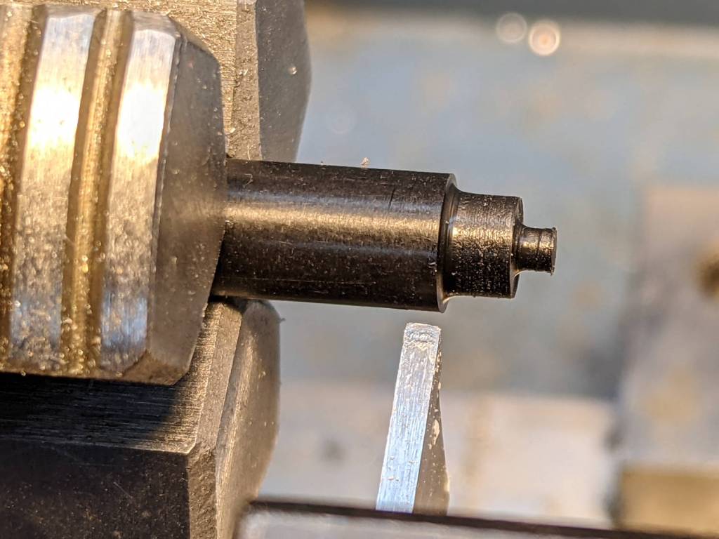
Rather than glue a PETG filament snippet into a screw, I turned a little Delrin plug:
Tour Easy Rear Fender Bracket – screw insert
It’s ready for installation when I’m willing to put the bike up on the rack and pull the rear wheel:
Tour Easy Rear Fender Bracket – screw detail
That’s actually the second iteration for the screw, as the first suffered a lethal encounter with the Greater Shopvac. I know exactly where it is, but I’m not going there …
For unknown reasons, the Bafang BBS02 motor puts the left pedal 15.5 mm closer to the frame than the right pedal:
Bafang BBS02 dimensions
The diagram presents the motor assembly as seen from the bottom, lying on the ground looking upward with your feet forward around the front wheel.
That much offset may be acceptable for some (upright?) bikes and some riders, but this seemed better for Mary:
Tour Easy – Lekkie 160mm offset crank – installed
Lekkie Buzz Bars have a matching 15.5 mm offset in the left crank to center both pedals on the frame. She’s been pushing 165 mm cranks for long enough to know standard 170 mm cranks require too much leg travel, so that’s a 160 mm Lekkie crank.
With cranks installed in the BBS02, measured from the frame tube to the inside of the crank at the pedal axis:
Bafang 170 mm: L 42, R 62
Shimano 105 triple 170 mm: L 46, R 67
Lekkie 160 mm: both sides 60
For comparison, the Shimano 105 cranks on my Tour Easy measure 35 mm on both sides with an ordinary Shimano UM-BB72 bottom bracket cartridge, so the BBS02 + Lekkie cranks put each pedal 25-ish mm farther out. However,my pedals screw into 20 mm Kneesavers, putting them pretty close to the Lekkie spacing.
We hope the additional space won’t make much difference to Mary; it’s certainly better than sitting offset to the right to match the pedals, as she’s found herself doing with both the Bafang and Shimano cranks on the BBS02. Her right shoe just barely tapped the crank, so we moved the cleat a few millimeters inboard and it’s all good again.
The Cateye cadence sensor now has a rakish tilt to match the crank offset and looks scarily exposed. More riding is in order.
The Lekkie cranks have a hollow cross-section that’s concave on the frame side, so the magnet sits on a simple riser to get it out where the sensor can experience it:
It’s held in place with good foam tape; the cable tie makes me feel better.
The OpenSCAD code for the riser fits into the GitHub Gist:
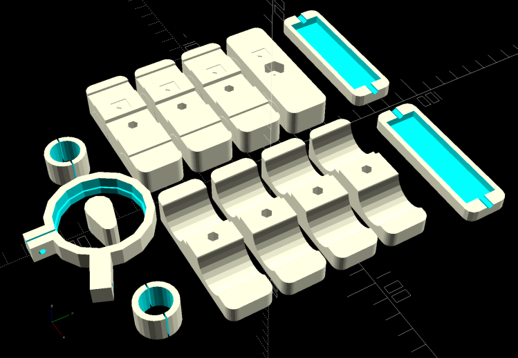
Bafang Battery Mount – build view – cadence magnet
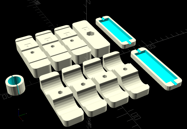
In point of fact, that array pretty much fills the M2’s platform and would require over 11 hours of print time, which is just crazy talk. Have the slicer break it into separate parts, delete whatever you don’t want at the moment, print what’s left, and iterate until you have everything you need to finish the job.
For inscrutable reasons, the Bafang 500C display includes all stopped time in its average trip speed. While that is, in fact, the average speed over the entire trip, the Cateye cyclocomputers we’ve been using forever stop averaging after a few seconds at 0 mph.
Bonus: Although the Bafang BBS02 motor knows the pedal cadence, it’s not part of the display.
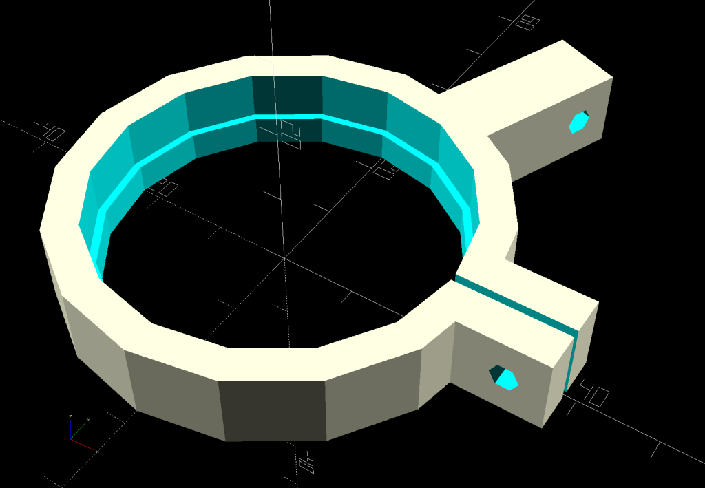
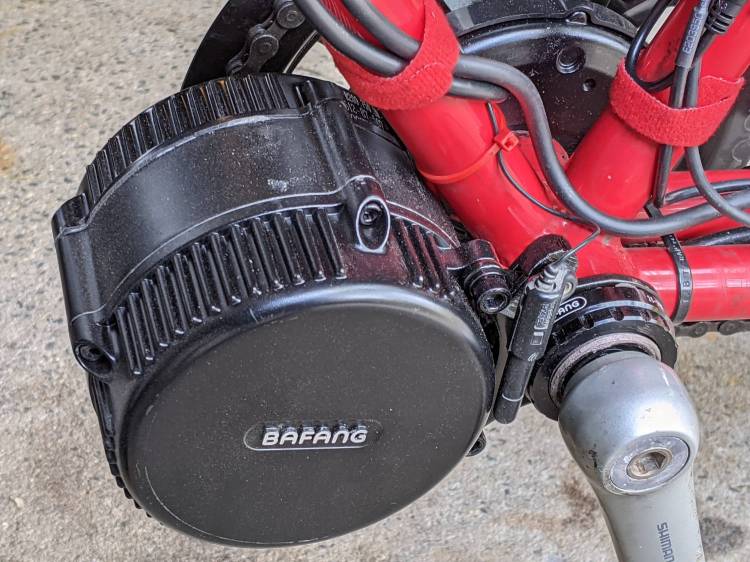
The Bafang BBS02 bottom bracket shaft put its pedal cranks much farther from the Tour Easy’s frame than the Shimano cranks, to the extent that the existing Cateye cadence sensor position just wasn’t going to work, so I printed a simple clip to fit over the motor’s “fixing plate”:
Tour Easy Bafang BBS02 motor
It turns out putting a magnetic sensor immediately next to the winding end of a high-current three-phase motor isn’t the brightest idea I’ve ever had. The Cateye cadence display spent most of its time maxed out at 199 rpm, far faster than Mary can spin for, well, a single revolution.
A somewhat more complex mount put the sensor roughly where it used to be:
Cateye Cadence Sensor mount – installed
It looks precarious, but it spent nigh onto two decades there without incident, so we have precedent.
Those are the original 165 mm Shimano cranks, because the 170 mm Bafung cranks threatened to lock out her knees. More on this in a while, as it’s a more complex issue than it may appear.
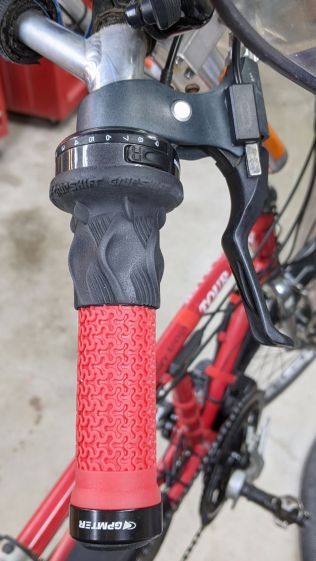
Installing the Bafang BBS02 motor on Mary’s Tour Easy replaced the triple chainring, so I removed the front derailleur and SRAM grip shifter. This produced enough room for the thumb throttle and a full-length handgrip on the left side:
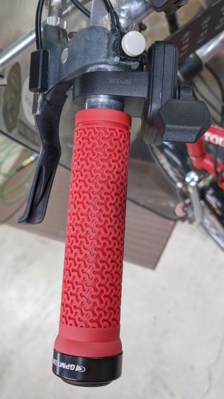
The right handlebar still has the rear shifter, so it requires a shorter grip:
Tour Easy grips – right installed
Although it may be possible to buy such a grip and, thereby, get a backup pair of mismatched grips, it seemed easier straightforward to just shorten the grip to the correct length and be done with it.
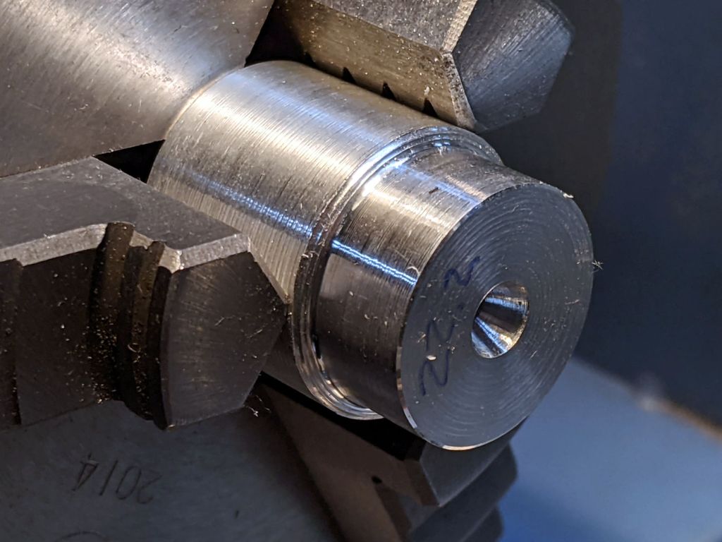
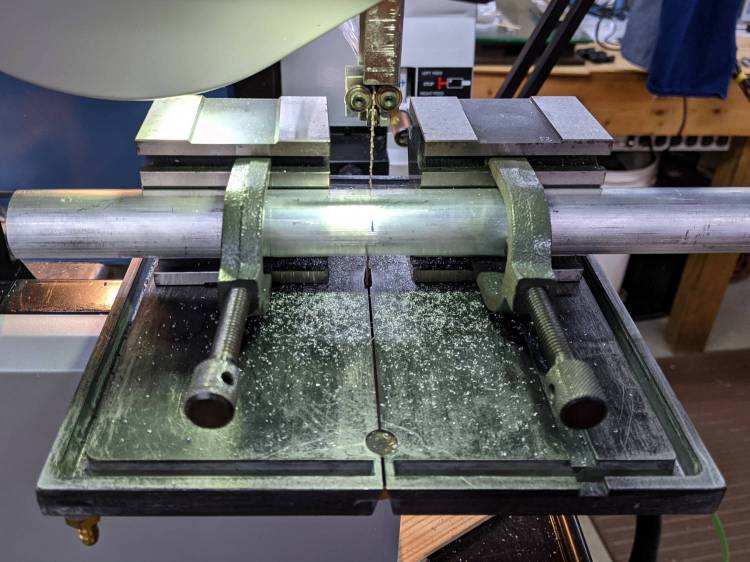
Saw off a convenient length of aluminum rod:
Tour Easy grips – mandrel sawing
Although I actually used a steady rest to produce this, it happened during a remote Squidwrench meeting and I have no proof:
Tour Easy grips – lathe mandrel
The 22.2 mm = 7/8 inch end matches the more-or-less standard handlebar diameter, so the grip clamp can get a good hold:
Tour Easy grips – right peeled
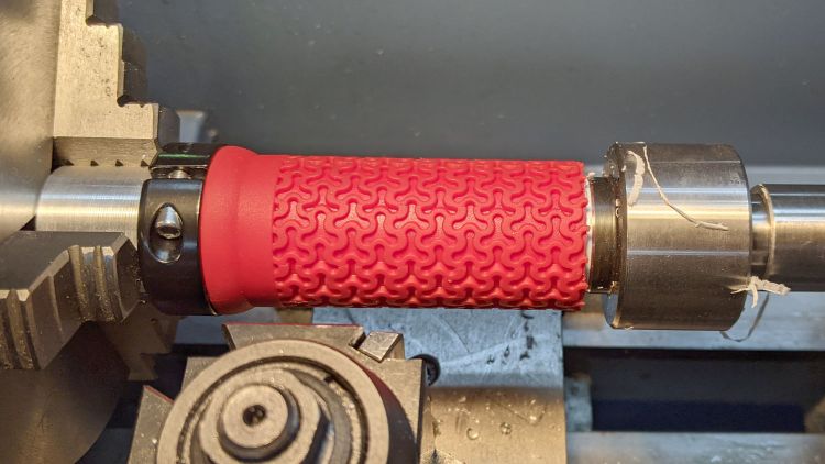
A live center supports the right end of the grip.
The red coating seems to be gooey silicone rubber molded atop a PVC tube. Rather than (try to) use a lathe bit to cut through the silicone, I cut two slits with a utility knife and the spindle turning slowly in reverse, then peeled off the rubber between the slits.
With the silicone out of the way, an ordinary cutoff tool made short work of the PVC:
Tour Easy grips – right trimming
That was a cleanup pass with the utility knife, as the cutoff tool left a slight flange around part of the circumference. If I had the courage of my convictions, I could probably have cut the PVC with the knife.
Chamfer the end of the cut, slide it on the handlebar, tighten the clamp, and it’s all good.
The alert reader will note the clamp should go on first, but that would produce an inconvenient lump against the right shifter. Sliding them on backwards puts the clamp at the end of the handlebar and works out better in this admittedly unusual situation.
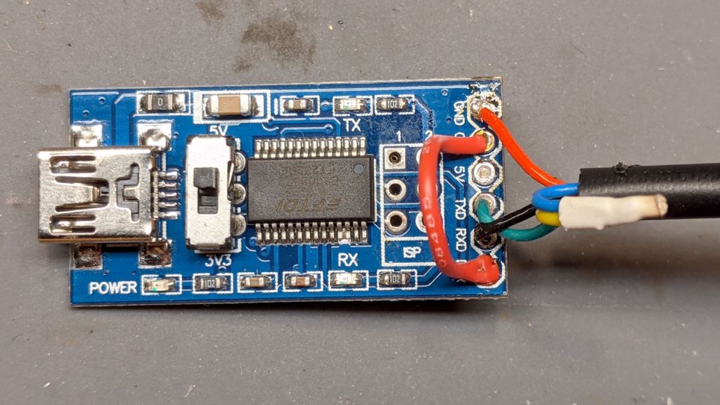
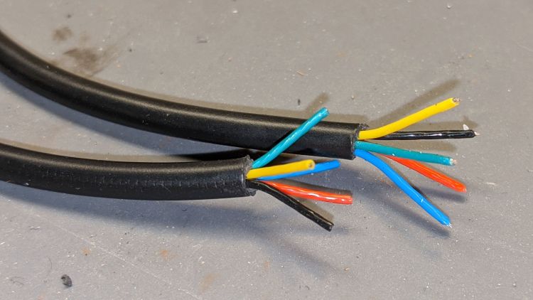
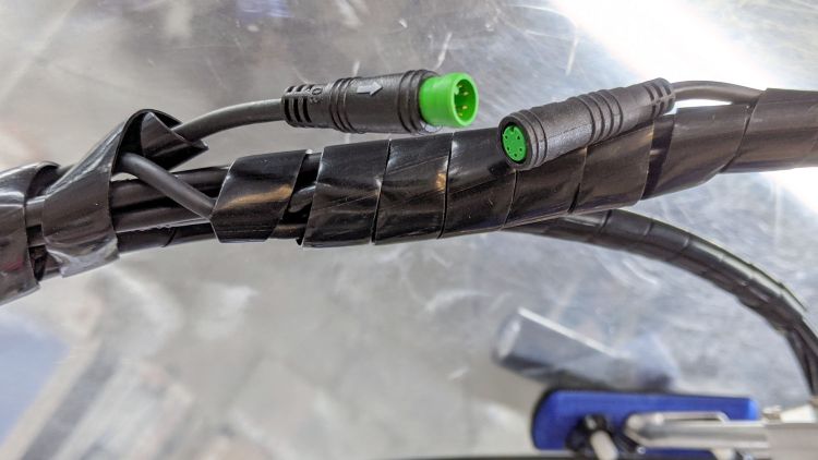
Changing (“programming”) the Bafang BBS02 motor controller parameters requires a USB-to-serial adapter with a connector matching the end of the cable from the motor to the display. While you can buy such things directly from the usual randomly named Amazon sellers, I happen to have a wide variety of bare adapter boards, so I just bought a display extender cable and cut it in half to get the connector; you can apparently buy pigtailed connectors (for more than the price of an extender) if you dislike cutting cables in half.
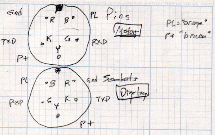
Various documents provide versions of the canonical illustration of the motor end of the display cable, as ripped from Penoff’s original documentation:
Note that the yellow-blue connection carries the full 48 V from the battery and may or may not have any current limiting / fusing / protection, so be a little more careful than usual in your wiring layout.
The red jumper from DTR to CTS, shown in all the Amazon and eBay listIngs, turns out to be unnecessary.
A quick and dirty case (eventually held together with generous hot-melt glue blobs) protects the PCB and armors the cables:
Bafang USB-serial adapter interior
The solid model over on the right looks about like you’d expect:
Bafang Battery Mount – complete build view
Most of the instructions will tell you to hot-plug the cable to the motor with the battery connected, which strikes me as foolhardy; not all of those pins make contact in the right order, which means you will slap 50-odd volts across the wrong parts of the circuitry.
Instead:
Disconnect the battery
Unplug the display
Plug the adapter cable into the motor connector
Plug the USB cable into the Token Windows Laptop
Reconnect the battery
Fire up the “programming” routine
Send the new configuration to the motor controller
Disconnect the battery
Unplug the adapter cable
Reconnect the display cable
Reconnect the battery
Makes more sense to me, even if it’s more tedious.
Over the decades, we have devoted considerable time and attention to adjusting the reach and travel of the brake levers on Mary’s bike, so I ordered a pair of brake sensors for the Bafang BBS02 motor to mount on the existing hardware:
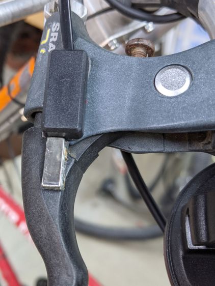
Tour Easy Bafang BBS02 – brake sensor – installed
The sensor is the black block secured to the brake mount (with good outdoor foam tape), with the bar magnet similar secured to the handle. The magnet ended up slightly off-center from the switch due to the overlapping joint between the lever and the mount; I can’t detect any difference from having it centered.
The Bafang switches included cute little disk-shaped neodymium magnets which weren’t suited for the levers and stuck out in all directions without getting particularly close to the sensor. As a result, the least pressure on the brake handle produced a hair-trigger switch activation.
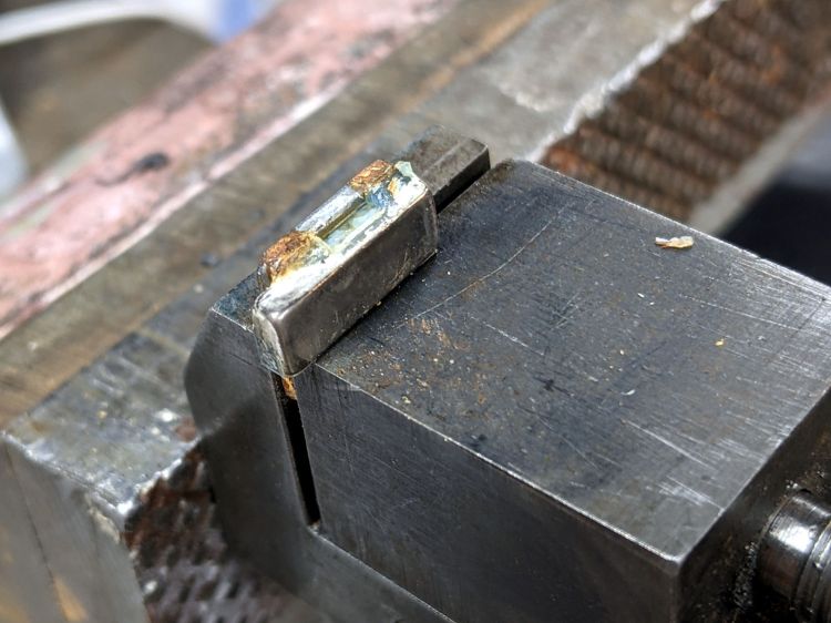
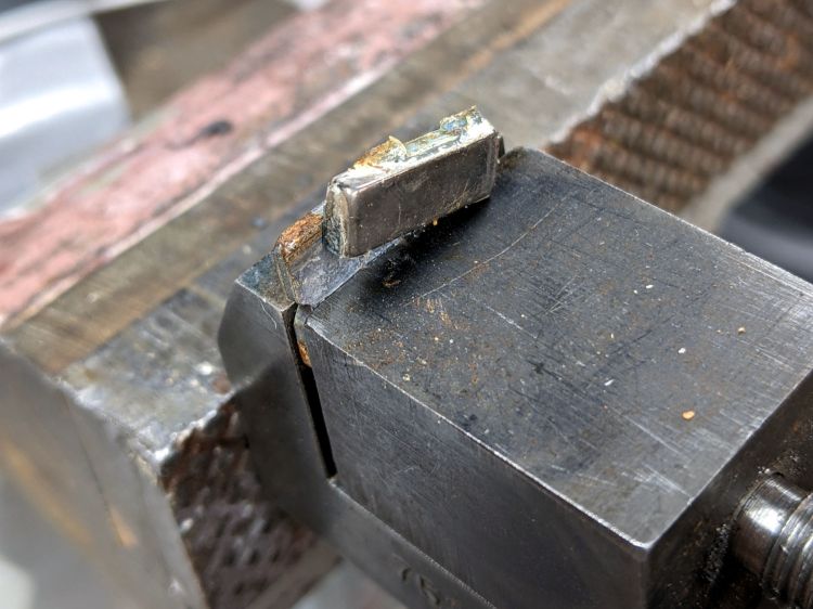
So I harvested two bar-shaped magnets from a defunct Philips Sonicare toothbrush head, reducing the rather large assortment I’ve been saving for just such an occasion by one item. Each brush head contains a pair magnets attached to a steel backing plate, seen here after removing the lower magnet:
I don’t know how Philips attaches the magnets, but a few shots to the steel backing plate with a drift punch breaks the bond without any obvious damage:
Neodymium magnets have a nickel plating to prevent corrosion, but AFAICT the only way to know whether I’ve cracked the plating is waiting to see if the magnet falls apart. If it does, I promise to be more careful with the next toothbrush head.
They’re magnetized through the thinnest section, not along the length like an old-school bar magnet, but the disk magnets are similarly magnetized and I think the net effect is about the same.
The bars fit the brake handles more closely, put more of the magnet closer to the switch, and allow about 5 mm of travel before tripping the switch.
Pending more road testing, the switches seem more usable.
Protip 1: Demagnetize your tools after working with neodymium magnets.
Protip 2: Don’t put a loose magnet anywhere near your bench block, because it will shatter when it snaps onto the block from a surprising distance.