This one grew along a trail in the Cary Institute of Ecosystems Studies forest:
It makes a great landscape monitor background…
The Smell of Molten Projects in the Morning
Ed Nisley's Blog: Shop notes, electronics, firmware, machinery, 3D printing, laser cuttery, and curiosities. Contents: 100% human thinking, 0% AI slop.
Taking & making images.
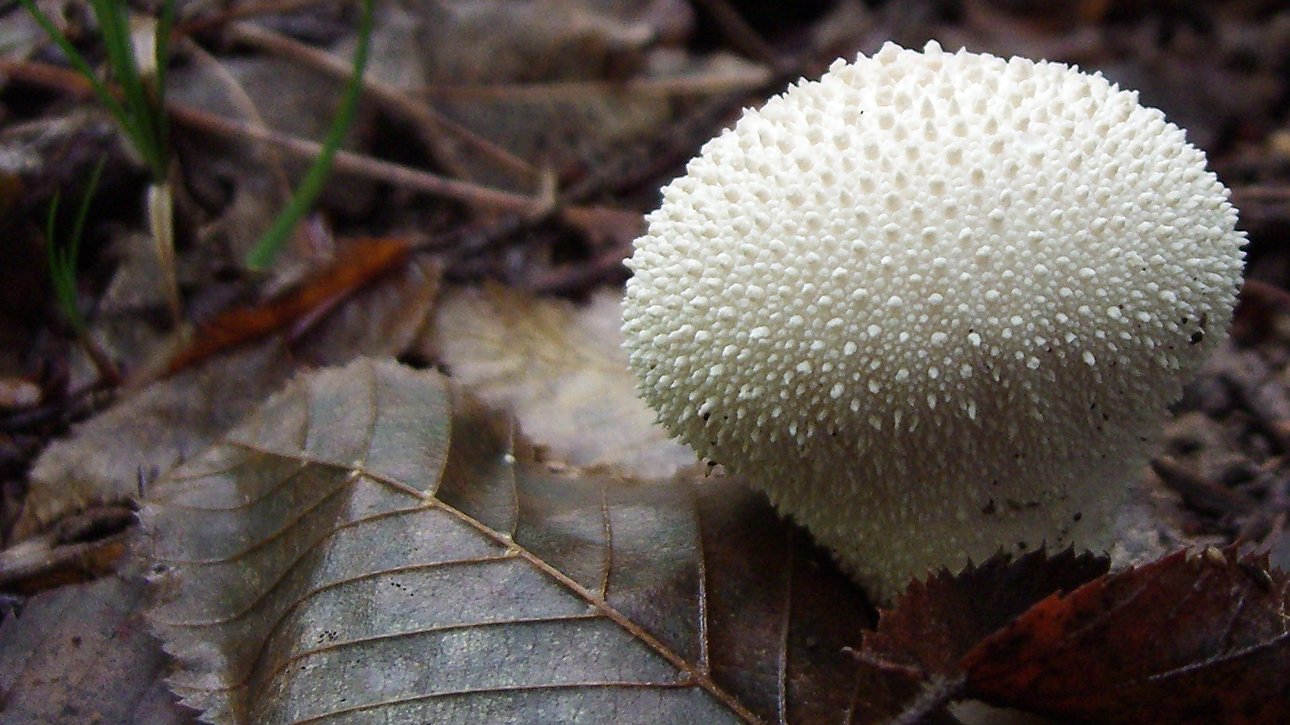
This one grew along a trail in the Cary Institute of Ecosystems Studies forest:
It makes a great landscape monitor background…

This wonderful texture lives at the top of Cochran Hill Road, where I spotted it on a recent walk. That tiny hole on the right trunk suggests more trouble than meets the human eye…
It’s now a background for the portrait monitor.
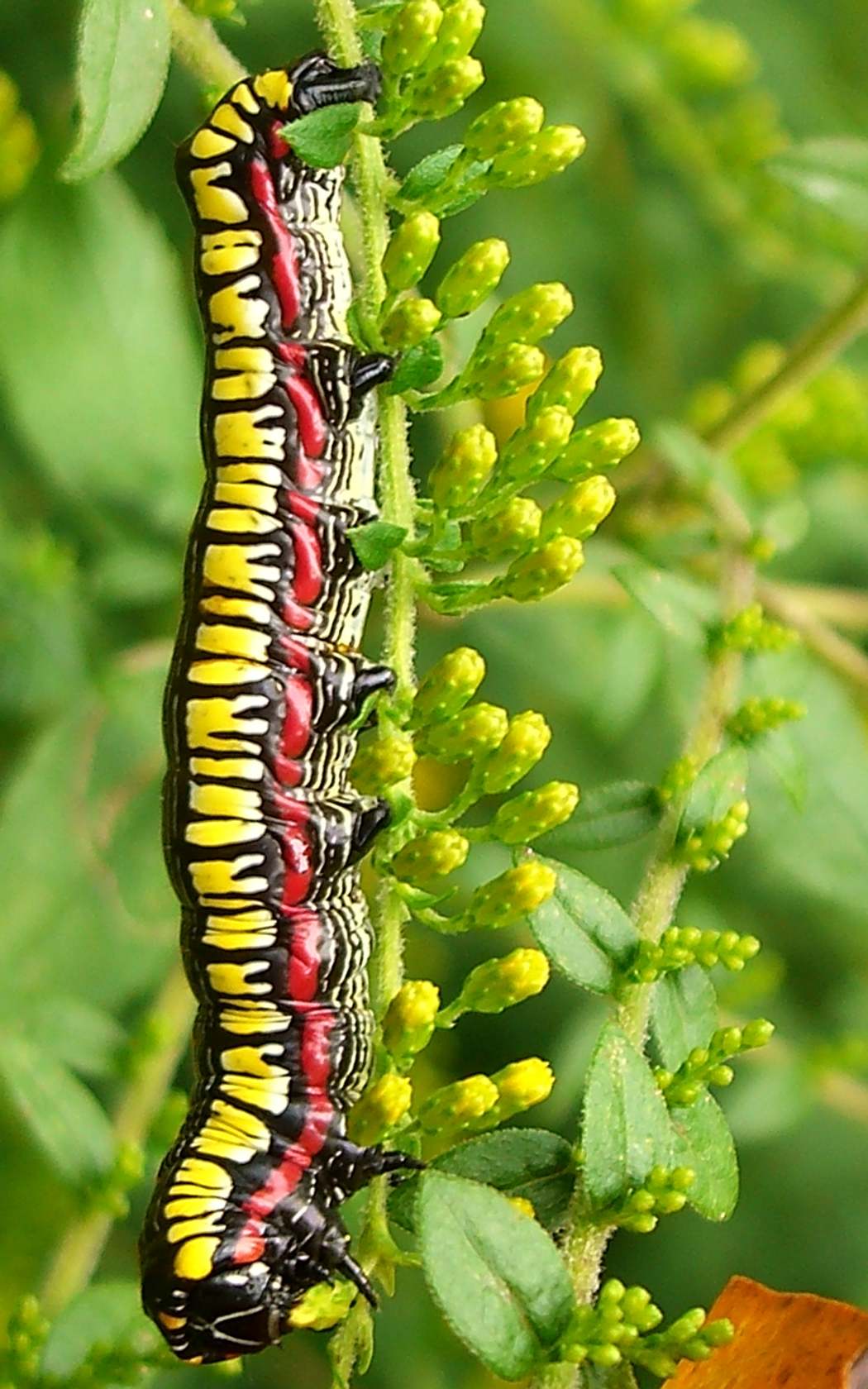
This critter lived at the Cary Institute for Ecosystems Studies in Millbrook, back in 2006. I have no idea what it grew up to be, but the picture is one of my all-time favorite portrait-mode monitor backgrounds.
Hand-held with the little Casio EX-Z850 camera (which is now with our Larval Engineer), ruthlessly cropped from a much larger image, and resized to fit the monitor…
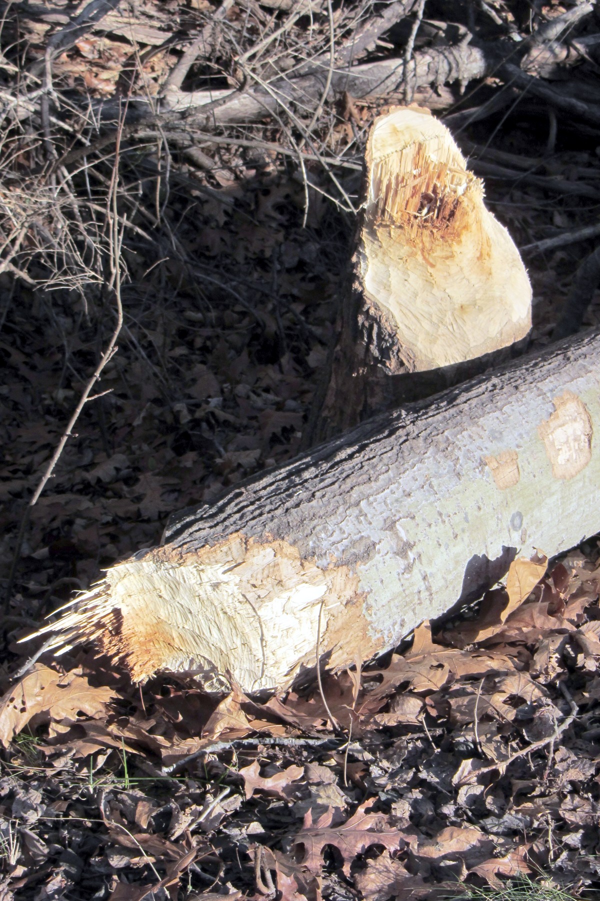
I spotted this bit of engineering while riding on the Dutchess Rail Trail at Lake Walton:
Evidently, the beaver stopped just before the tree toppled, because the last cut looks very much like a chainsaw.
I didn’t spot their lodge out in the lake; they may have tucked it under the bank below the railroad bed.
If they keep this up, they’re sure to get trapped and moved somewhere they can’t interfere with our enjoyment of the natural landscape along the rail trail. [wince]
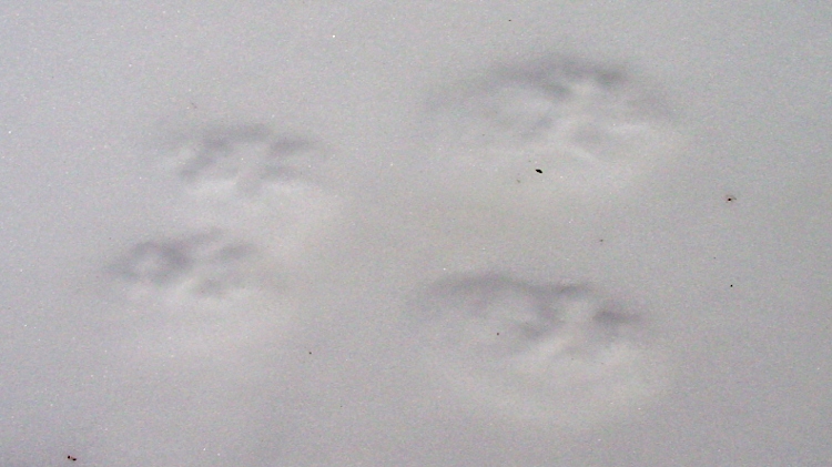
Our back yard serves as a wildlife thoroughfare, but only after a snowfall can we see who’s been afoot overnight.
Gray squirrels hop across the driveway:
When they’re not busy raiding the bird feeder, that is:

Red foxes leave widely spaced tracks:

Even quadrupeds have trouble maintaining their footing on an icy driveway:

Turkeys travel in flocks:

And sometimes monsters stride the Earth:

Seeing as how it wouldn’t be a suitable blog post without some numbers, here’s a 1 foot / 30 cm scale with fox and turkey tracks:

Those are scary-big birds!
Merry Christmas to all!
Just got an ultraviolet LED in a 10 mm epoxy package that’s water-clear in visible light and slightly fluorescent in its own UV:

The epoxy usually has some fluorescence, but this seems more dramatic than usual. In any event, the die’s wide beam angle shows clearly; the beam along the axis out in front is actually pretty tight.
It’s sitting on the back of a white ceramic tile and the colors came out surprisingly close to real life.
Adding this to an Arduino would follow the same logic as, say, the pager motor: power the LED + resistor + MOSFET from a +5 V external regulator that won’t heat the Arduino board, then define an unused bit in the shift register as, say UV_LED.
It runs at 20 mA and drops around 3.3 V.
My father obviously devoted considerable time to drawing the gills on this critter in his Sophomore Biology Notebook:
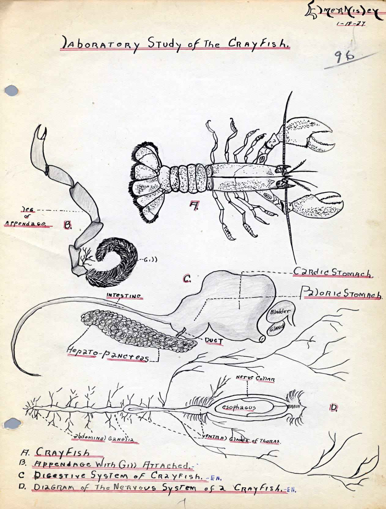
The stomach and nervous system seem sufficiently stylized that they’re not drawn from a specimen; I’m pretty sure a real crayfish doesn’t come apart quite so neatly.
Our Larval Engineer reports that the lab sessions for her second quarter of Anatomy and Physiology will involve dissecting sheep hearts and eyeballs (which arrive in plastic buckets festooned with hazmat stickers for the preservative). She regards this as more than making up for having to sit through A&P lectures and memorizing all those bones & muscles. Must be another generation-skipping trait, is all I can say…
