Ed Nisley's Blog: Shop notes, electronics, firmware, machinery, 3D printing, laser cuttery, and curiosities. Contents: 100% human thinking, 0% AI slop.
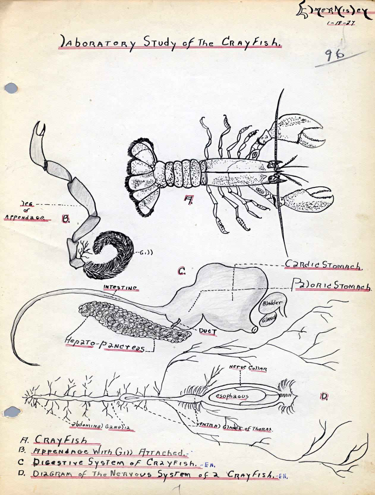
My father obviously devoted considerable time to drawing the gills on this critter in his Sophomore Biology Notebook:
Laboratory Study of the Crayfish
The stomach and nervous system seem sufficiently stylized that they’re not drawn from a specimen; I’m pretty sure a real crayfish doesn’t come apart quite so neatly.
Our Larval Engineer reports that the lab sessions for her second quarter of Anatomy and Physiology will involve dissecting sheep hearts and eyeballs (which arrive in plastic buckets festooned with hazmat stickers for the preservative). She regards this as more than making up for having to sit through A&P lectures and memorizing all those bones & muscles. Must be another generation-skipping trait, is all I can say…
Having established the OpenSCAD can produce a height map from an input array, a bit more doodling showed how to produce such an array from a grayscale image. I certainly didn’t originate all of this, but an hour or two of searching with the usual keywords produced snippets that, with a bit of programming-as-an-experimental-science tinkering, combine into a useful whole.
Not being much of an artist, I picked a suitable SVG image from the Open ClipArt Library:
Jellyfish – color
That’s pretty, but we need a grayscale image. Some Inkscape fiddling eliminated all the nice gradients, changed the outline to a dark gray, made all the interior fills a lighter gray, and tweaked the features:
Jellyfish – gray
Admittedly, it looks rather dour without the big smile, but so it goes. This is still an SVG file, so you have vector-mode lines & areas.
A bit more work changed the grays to produce different heights, duplicated one of the spots for obvious asymmetry, and exported it as a gritty 160×169 pixel PNG image:
Jellyfish – height map image
The low resolution corresponds to a 2 pixel/mm scale factor: 169 pixel = 84.5 mm tall. The cutter wrapped around this image will have a lip that adds about 12 mm, a 1 or 2 mm gap separates the press from the cutter, and there’s a skirt around the whole affair. My Thing-O-Matic build platform measures a scant 120 mm in the Y direction, which puts a real crimp on the proceedings.
That’s assuming the usual 1 unit = 1 mm conversion factor. If your toolchain regards units as inches, then you need a different scale factor.
Low resolution also speeds up the OpenSCAD processing; you can use as many pixel/mm as you wish, but remember that the extruded filament is maybe 0.5 mm wide, so anything beyond 4 pixel/mm might not matter, even if the motion control could benefit from the smoother sides. Features down near the resolution limit of the model may produce unusual effects for thin walls near the thread width, due to interpolation & suchlike (which is why I got rid of the smile). The processing time varies roughly with the number of pixels, so twice the resolution means four times more thumb-twiddling.
Caveats:
You’re looking at a cookie lying on a table: this is the top view
Background surrounding the image should be full white = 255
Highest points should be very light gray, not full white, to avoid creating islands
Lowest points may be black; I use a very dark gray
No need for an outline
Smooth gradients are OK, although they’ll become harshly quantized by the layer thickness
You can probably use JPG instead of PNG, but these aren’t big files
Remember this is a cookie press, not a work of art
With a suitable PNG image file in hand, use ImageMagick to prepare the image:
Crop to just the interesting part: -trim (depends on the four corners having background color)
Convert the image to grayscale: -type Grayscale (in case it’s a color image)
Make it 8 bit/pixel: -depth 8 (more won’t be helpful)
Stretch the contrast: -auto-level (to normalize the grayscale to the full range = full height)
Reverse left-to-right to make a cookie press: -flop (think about it)
Invert the grayscale to make the cookie press surface: -negate (again, think about it)
Reverse top-to-bottom to correct for upcoming OpenSCAD surface() reversal: -flip
Combining -flop and -flip just rotates the image 180° around its center, but I can’t help but believe transposing the bits works out better & faster than actually rotating the array & interpolating the result back to a grid. On the other paw, if there isn’t a special case for (multiples of) right-angle rotation(s), there should be. [grin]
The prepared image is 149×159, because the -trim operation removed the surrounding whitespace. You can do that manually, of course, keeping in mind that the corners must be full white to identify the background.
Next: convert that image to a data array suitable for OpenSCAD’s surface() function…
During that ride for apples, we stopped for lunch in the middle of the Walkway where the scenery is a lot better and the traffic much more pleasant than elsewhere along our route:
Poughkeepsie Bridge
For reasons that have nothing to do with engineering judgement, the west (right) end of the Mid-Hudson Bridge terminates at a cliff with the road in a monster cut turning abruptly to the right and ramping up to the toll plaza. It’s still a pretty span…
Back in December 2007 I printed four copies of a picture on various papers with the Canon S630 and hung them on a floor joist over my workbench, directly below a fluorescent shop light. Having just hung those screwdrivers where the pictures used to be, it’s time to see what’s happened.
The pictures, scanned on an HP C7670A (aka Scanjet 6300C) against the neutral gray of the ADF platen:
Inkjet Colors vs. Paper vs. Time
The papers, clockwise from lower left:
Glossy
Matte
Plain
Inkjet
While the scanner isn’t renown for its color fidelity, the overall results look about right; the platen really is that shade of gray and the upper-right picture has a sickly green hue.
The faded edges along the right side of the left-hand image show where the adjacent sheet overlapped: the colors didn’t fade nearly as much. The small rectangles on the lower left corners of the right-hand images show where I put clothes pins to keep the sheets from curling.
All of the images have a blue overtone; the magenta dye fades out with exposure to UV from the fluorescent fixture.
As you’d expect, the glossy paper looks best, with very crisp detail. The inkjet paper is next, followed by the matte, and the plain paper in the upper right obviously doesn’t support the ink well at all.
Of course, after five years I no longer have any of those papers and am using entirely different ink…
To show that the scanner really does matter, here’s the same set of images from a Canon LiDE 30:
Inkjet Colors – Canon LiDE30
In both cases. that’s without any color correction / gamma compensation / whatever. I should fish out my scanner calibration targets and go through the whole color calibration dance again; with any luck, the Linux color management infrastructure will be less inadequate by now.
This looks like a juvenile Cooper’s Hawk, perched high atop that tree. It seems the pair we spotted last year had a successful hatching!
We always wish “our” hawks, whatever and wherever they may be, good hunting…
This came from the first set of real pictures using the repaired Sony DSC-H5 zoomed to 12× with the 1.7× tele conversion lens, cropped down a bit: plenty of artifacts to choose from.
The plunger is basically a pin that eventually deforms the top of the switch membrane. Tee’s DSC-H1 had an exposed switch, although this picture shows that membrane was still in reasonably good condition:
Shutter Switch Closeup
My DSC-H5 has a thin black protective disk atop the switch, but the disk wasn’t particularly protective and developed a dimple that held the contacts closed even with the shutter button released (which is why I’m tearing the camera apart in the first place):
DSC-H5 Shutter Switch – dimpled protector
The C-clip around the plunger is now plastic, rather than metal, making it less likely to erode the thin plastic shaft. Pulling the clip off while holding the button down releases all the parts:
DSC-H5 Shutter Button – components
A few measurements from an intact shutter button, which may come in handy if you don’t have one:
DSC-H5 Shutter Button – plunger measurements
Mount three-jaw chuck on the Sherline table, laser-align chuck to spindle, grab shutter button by its shaft in a Jacobs chuck, grab shutter button in three-jaw chuck, release from Jacobs chuck:
DSC-H5 Shutter Button – in Sherline chuck
That’s not particularly precise, but it’s close enough for this purpose. I used manual jogging while testing the fit with a paper shim until all three jaws had the same clearance, then tightened the jaws.
I nicked the plunger at its base with a flush-cutting diagonal cutter, snapped off the plunger, and drilled a #56 hole through the button:
DSC-H5 Shutter Button – cap drilling
For reasons that made sense at the time, I repaired Tee’s DSC-H1 with a 1-72 brass screw. This time, I used an 0-80 (which I learned as ought-eighty, if you’re wondering about the indefinite article) screw and nut, because the screw head fit neatly into the bezel recess and I had a better idea of how to smooth out the threads.
This being plastic, I used the chuck to hold the tap in the proper alignment, then turned the tap through by finger pressure. This trial fit showed it worked:
DSC-H5 Shutter Button – 0-80 screw
Milling the nut down to a 2.8 mm cylinder required the usual manual CNC, with repeated iterations of this chunk of code in the MDI panel:
The 2.8 in the first line is the current OD and the 3.11 is the measured diameter of the 1/8 inch end mill. I started from a 5.0 mm OD that just kissed the nut, then worked inward by 0.2 mm at a time for very shallow 0.1 mm cuts:
DSC-H5 Shutter Button – 0-80 nut milling
The alert reader will notice, as did I, that the head isn’t quite centered: the cut trimmed the left side and left the right untouched, with an offset far larger than the centering error. As nearly as I can tell, the heads of those screws aren’t exactly centered on their threaded shafts, but the final result fixed that… and the overall error is a few tenths of a millimeter = maybe 10 mils, tops, so it’s no big deal.
With all that in hand, I applied a very very thin layer of epoxy to fill the threads below the now-cylindrical nut and convert the screw into a rod:
DSC-H5 Shutter Button – 0-80 plunger
My original intent was to use the screw head as-is atop the PET shield (per those instructions) on the switch membrane, but after reassembling enough of the camera to try that out, it didn’t work correctly: the half-pressed switch didn’t activate reliably before the full-pressed switch tripped.
The PET shield I used came from the side of a 1 liter soda bottle and turned out to be 0.27 mm thick:
DSC-H5 Shutter Switch – cover removed
I think the PET shield would work with the original plunger shape concentrating the force in the middle of the shield, but the nice flat screw head spreads the force out over a wider area. As a result, the force required to close the half-pressed switch contacts was roughly the same as that required to close the full-pressed contacts; remember the nub on the bottom of the black plastic tray concentrates the force in the middle of the full-pressed switch membrane.
So I removed the PET shield, added a dot of epoxy to fill the screw slot and compensate for the missing shield thickness, then filed a flat to make a nice pad:
DSC-H5 Shutter Button – epoxy on plunger
Reassembling the camera once more showed it worked exactly the way it should. In fact, the button seems more stable than the OEM version, probably because the slightly enlarged plunger shaft fits better in the bezel. Too bad about those scuffs on that nice shiny button dome, though:
DSC-H5 – repaired shutter button
Tossing the leftover parts seems entirely appropriate…