This critter trundled across the driveway after a shower wetted the area:

They do some damage in the garden, but we let them alone elsewhere…
The Smell of Molten Projects in the Morning
Ed Nisley's Blog: Shop notes, electronics, firmware, machinery, 3D printing, laser cuttery, and curiosities. Contents: 100% human thinking, 0% AI slop.
Taking & making images.
This critter trundled across the driveway after a shower wetted the area:
They do some damage in the garden, but we let them alone elsewhere…
I tagged along on another Master Gardener field trip, this time to Innisfree Garden near Millbrook NY, and took a bunch of closeups. This was supposed to feature just the solitary bee working the blossom, but …

The little gadget off to the left blundered into the depth of field at exactly the right moment. Couldn’t do that again if I tried…
Maybe they’re wasps. It probably matters only to another insect of the opposite polarity.
Taken with the Sony DSC-H5, no lenses, hand-held. The image is a dot-for-dot crop from the full frame that’s exactly sized for my landscape monitor.
A brace of “Fashion” USB video cameras arrived from halfway around the planet. According to the eBay description and the legend around the lens, they’re “5.0 Megapixel”:
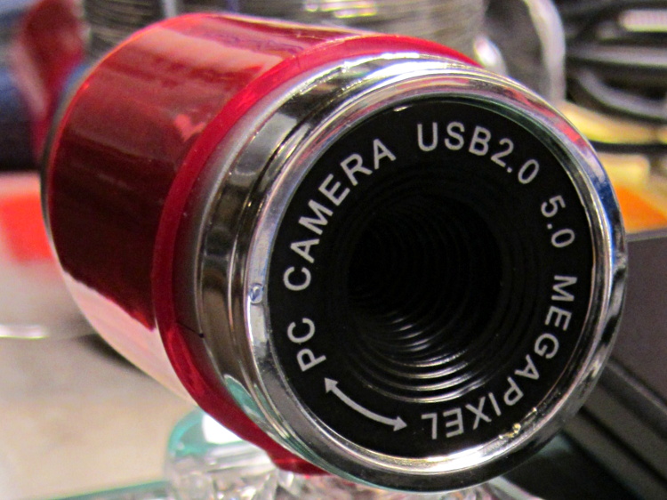
The reality, of course, is that for five bucks delivered you get 640×480 VGA resolution at the hardware level and their Windows driver interpolates the other 4.7 megapixels. VGA resolution will be good enough for my simple needs, particularly because the lens has a mechanical focus adjustment; the double-headed arrow symbolizes the focus action.
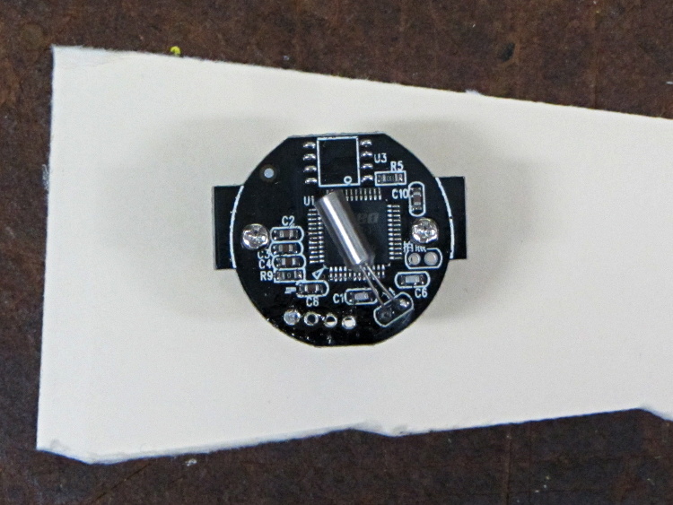
But the case seemed entirely too bulky and awkward. A few minutes with a #0 Philips screwdriver extracted the actual camera hardware, which turns out to be a double-sided PCB with a lens assembly on the front:

The PCB has asymmetric tabs that ensure correct orientation in the case:

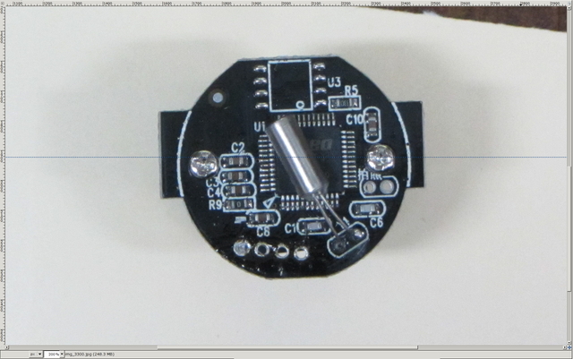
In order to build an OpenSCAD model for a more compact case, we need the dimensions of that PCB and those tabs…
Start with a picture of the back of the PCB against white paper, taken from a few feet to flatten the perspective:
Load it into The GIMP, zoom in, and pull a horizontal guide line down to about the middle of the image:
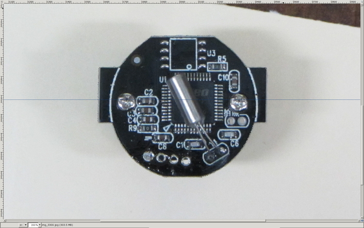
Rotate to align the two screws horizontally (they need not be centered on the guide, just lined up horizontally):

Use the Magic Scissors to select the PCB border (it’s the nearly invisible ragged dotted outline):
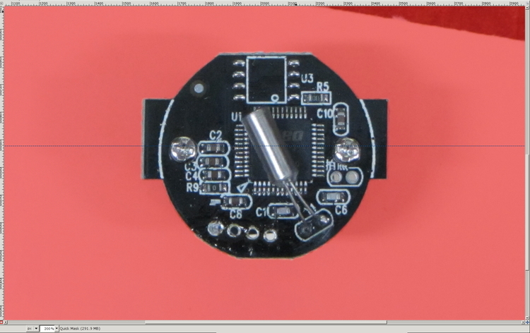
Flip to Quick Mask mode and clean up the selection as needed:
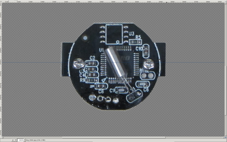
Flip back to normal view, invert the selection (to select the background, not the PCB), and delete the background to isolate the PCB:
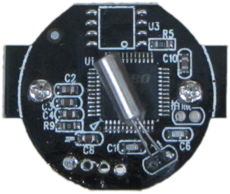
Tight-crop the PCB and flatten the image to get a white background:
Fetch some digital graph paper from your favorite online source. The Multi-color (Light Blue / Light Blue / Light Grey) Multi-weight (1.0×0.6×0.3 pt) grid (1 / 2 / 10) works best for me, but do what you like. Get a full Letter / A4 size sheet, because it’ll come in handy for other projects.
Open it up (converting at 300 dpi), turn it into a layer atop the PCB image, use the color-select tool to select the white background between the grid lines, then delete the selection to leave just the grid with transparency:
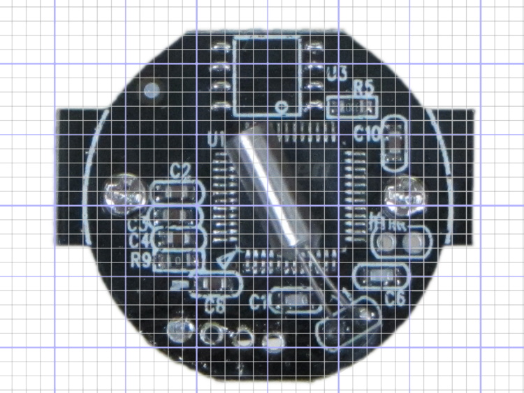
We want one minor grid square to be 1×1 mm on the PCB image, sooo…
That produces a calibrated overlay:
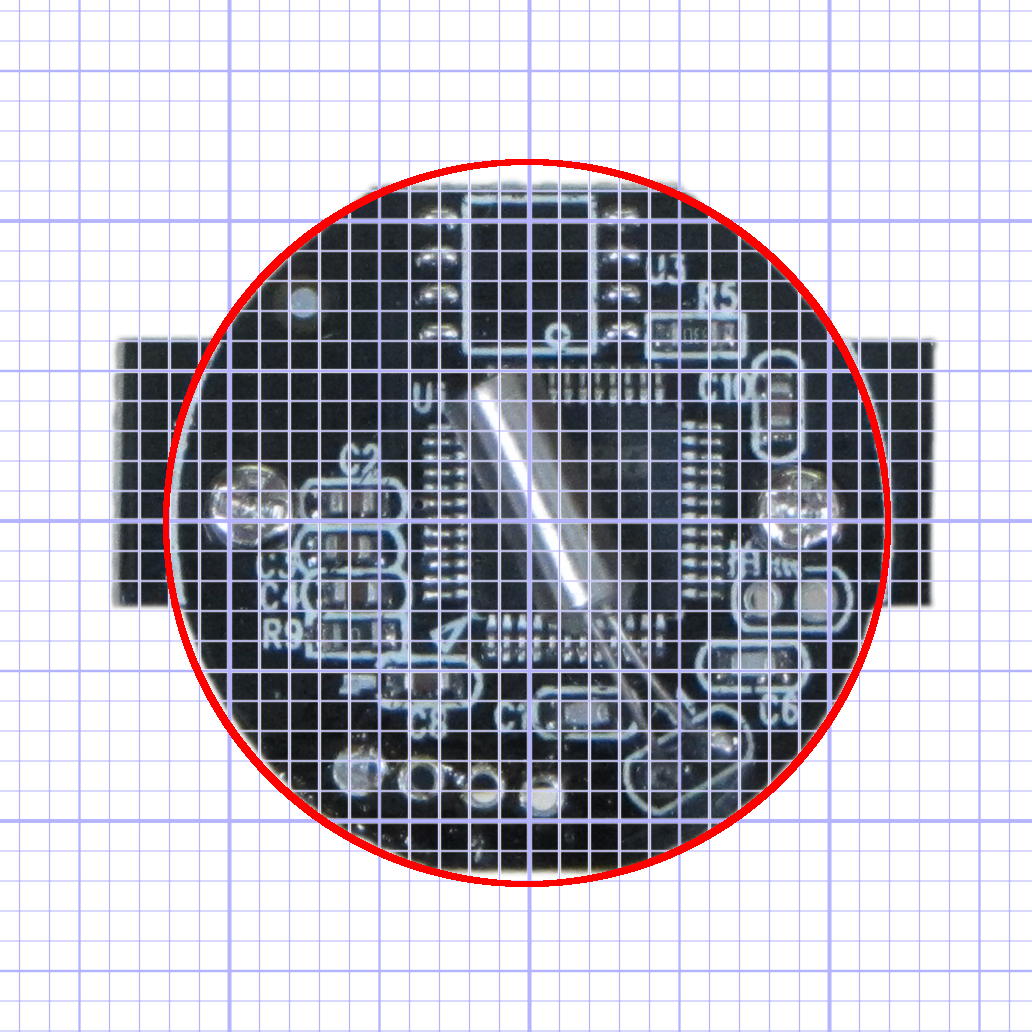
Then it’s just a matter of reading off the coordinates, with each minor grid square representing 1.0 mm in the real world, and writing some OpenSCAD code…
Mary’s been picking blueberries and freezing them for winter treats, a process that involves inspecting each berry laid out on the tray.
This one failed QC:

A closer look shows some remarkable structures:

Unfortunately, they’ll probably turn into Brown Marmorated Stink Bugs. This is not a Good Thing, because those stink bugs will devastate fruit harvests, including all the apple orchards along the entire Hudson Valley, over the next few years.
They may be Predatory Stink Bugs, which would be unusual in Dutchess County, but not nearly so awful.
One of my fundamental rules is that you should never, ever look inside the water lines serving your faucets. Having recently replaced a water heater, I had to violate that rule and discovered this growth inside the flex tube at the hot water outlet:
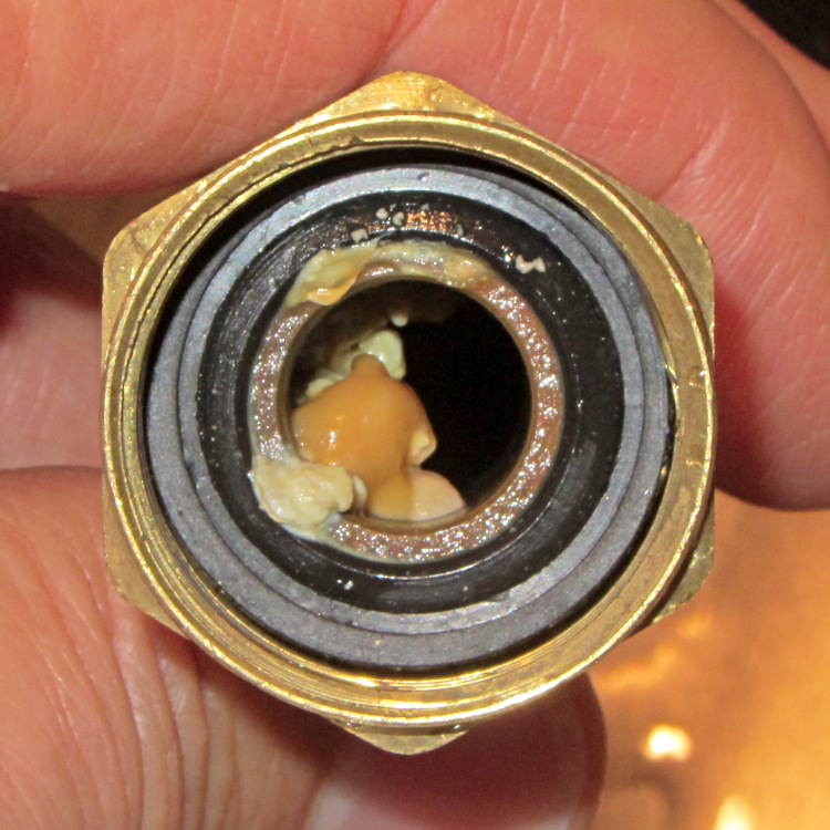
Anything that can thrive in 120 °F water gets my grudging respect.
Scrubbing it with a toothbrush produced gray sludge that rinsed right out, so I guess it’s all good now…
These guys just weren’t having a good day:

They’re members of the flock of six toms that marches through the neighborhood every day, clearing bugs out of the lawn.
We like ’em!
It should be possible to sense the filament diameter with a cheap webcam and some optics:

The general idea:
Given that LinuxCNC runs on a bone-stock PC, you can plug in a stock USB webcam and capture pictures (I have done this already). Because LinuxCNC isolates the motion control in a hard real time process, you can run heavy metal image manipulation code in userland (think ImageMagick) without affecting the motors.
So you can put a macro lens in front of a webcam (like that macro lens holder) and mount it just above the extruder with suitable lighting to give a high-contrast view of the filament. Set it so the filament diameter maps to about 1/4 of the width of the image, for reasons explained below.
For a crappy camera with 640×480 resolution, this gives you 160 pixel / 1.75 mm filament = 91 pixel/mm → about 0.01 mm resolution = 0.6%. Use a better camera, get better resolution: 1280 pixel = 0.3% resolution.
That gives you roughly 1% or 0.5% resolution in area. This is pretty close to the holy grail for DIY filament diameter measurement.
Add two first-surface mirrors / prisms aligned at right angles, so that the camera sees three views of the filament: straight on, plus two views at right angles, adjacent to the main view. Set the optics so they’re all about 1/4 of the image width, to produce an image with three parts filament and one part high-contrast background separating them. This is the ideal, reality will be messier.
Figure 1 shows an obvious arrangement, the mirrors in Figure 2 give more equal distances.
You could align the mirrors to provide three views at mutual 120° angles, which would equalize the distances and give you three identical angles for roundness computation, should that matter.
Diameter measurement process:
Adding binary pixels is easy: it’s just the histogram, which ImageMagick does in one step. Dump data to a file / pipe, process it with Python. It all feeds into a LinuxCNC HAL component, which may constrain the language to C / Python / something else.
(*) You can get vertical averaging over a known filament length, essentially for free. Extract three (or more) scan lines, process as above, divide by 3 (or more), and you get a nicely averaged average.
Win: the image is insensitive to position / motion / vibration within reasonable limits, because you’re doing the counting on pixel values, not filament position. The camera can mount near, but not on, the extruder, so you can measure the filament just above the drive motor without cooking the optics or vibrating the camera to death.
Win: it’s non-contacting, so there’s not much to get dirty
Win: you get multiple simultaneous diameter measurements around one slice of the filament
You could mount the camera + optics at one end of the printer’s axis (on the M2, the X axis). Drive the extruder to a known X position, take a picture of the straight-on view, drive to another position, take a picture of the mirrored views, and you have two pictures in perfect focus. Combine & process as above.
You can do that every now and again, because any reasonable filament won’t vary that much over a few tens of millimeters. Maybe you do it once per layer, as part of the Z step process?
You could generalize this to a filament QC instrument that isn’t on the printer itself: stream the filament from spool to spool while measuring it every 10 mm, report the statistics. That measurement could run without stopping, because you don’t reposition the filament between measurements: it’s all fixed-focus against a known background. You could have decent roller guides for the filament to ensure it’s in a known position.
Heck, that instrument could produce a huge calibration file that gives diameter / roundness vs. position along the entire length of the filament. Use it to accept/reject incoming plastic supplies or, even better, feed the data into the printer along with the spool to calibrate the extrusion on the fly without fancy optics or measurements.
Dan wonders if this might be patented. I’m sure it is: I’m nowhere near as bright as the average engineering bear at a company that’s been spending Real Money for three decades. My working assumption: all the knowledge is out there, behind a barrier I can’t see through or reach around: there’s no point in looking for it beyond a casual Google search on the obvious terms that, so far, hasn’t produced anything similar.
Memo to Self: Might even be marketable, right up until they crush me like a bug…
