When in doubt, use an endstop switch:
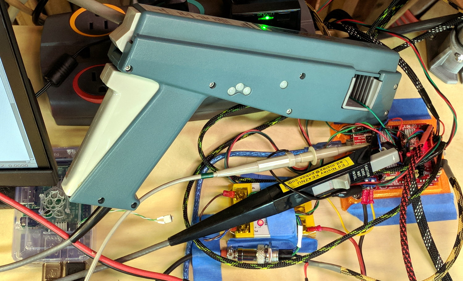
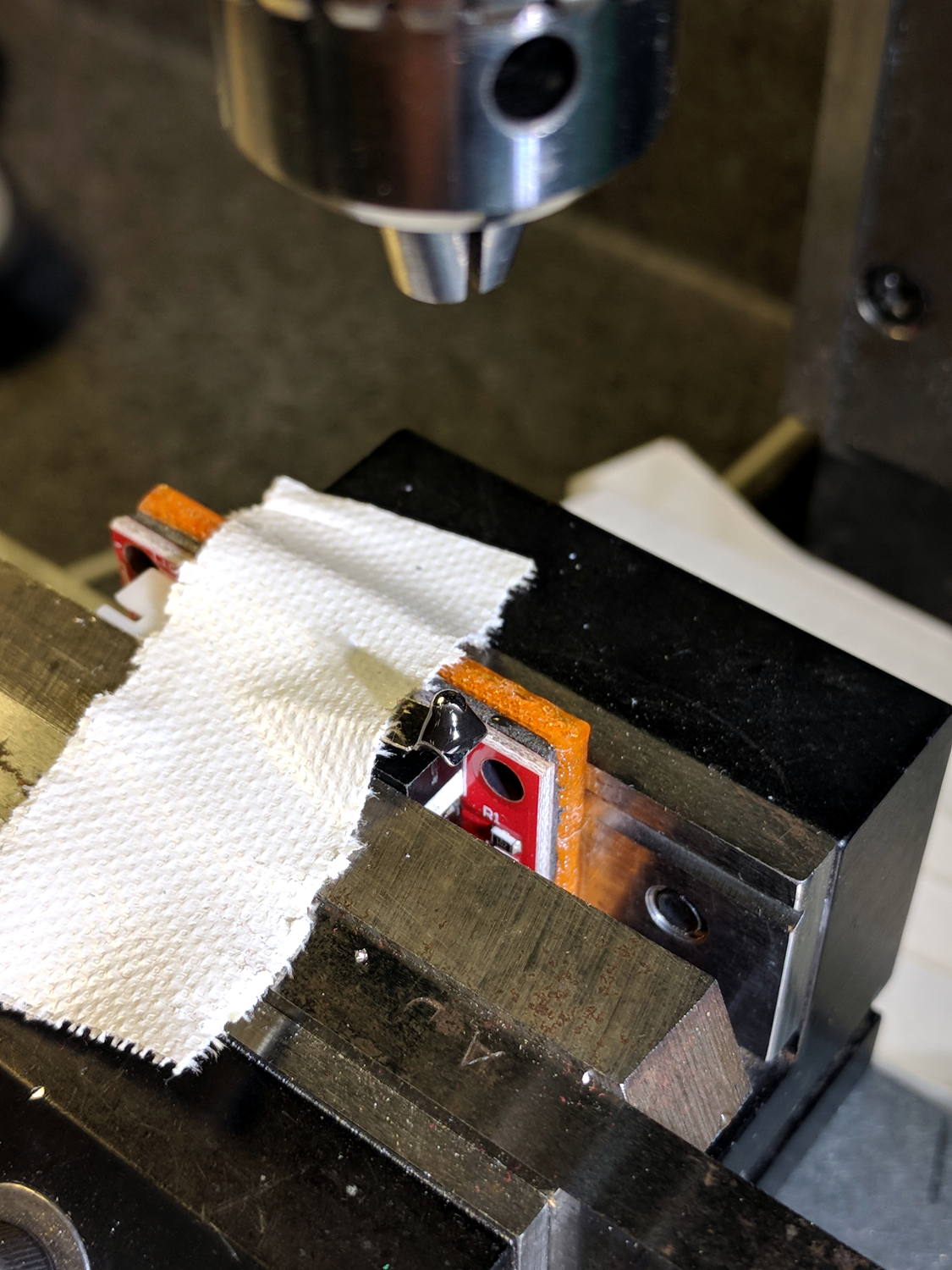
The USB camera lurks in the upper right.
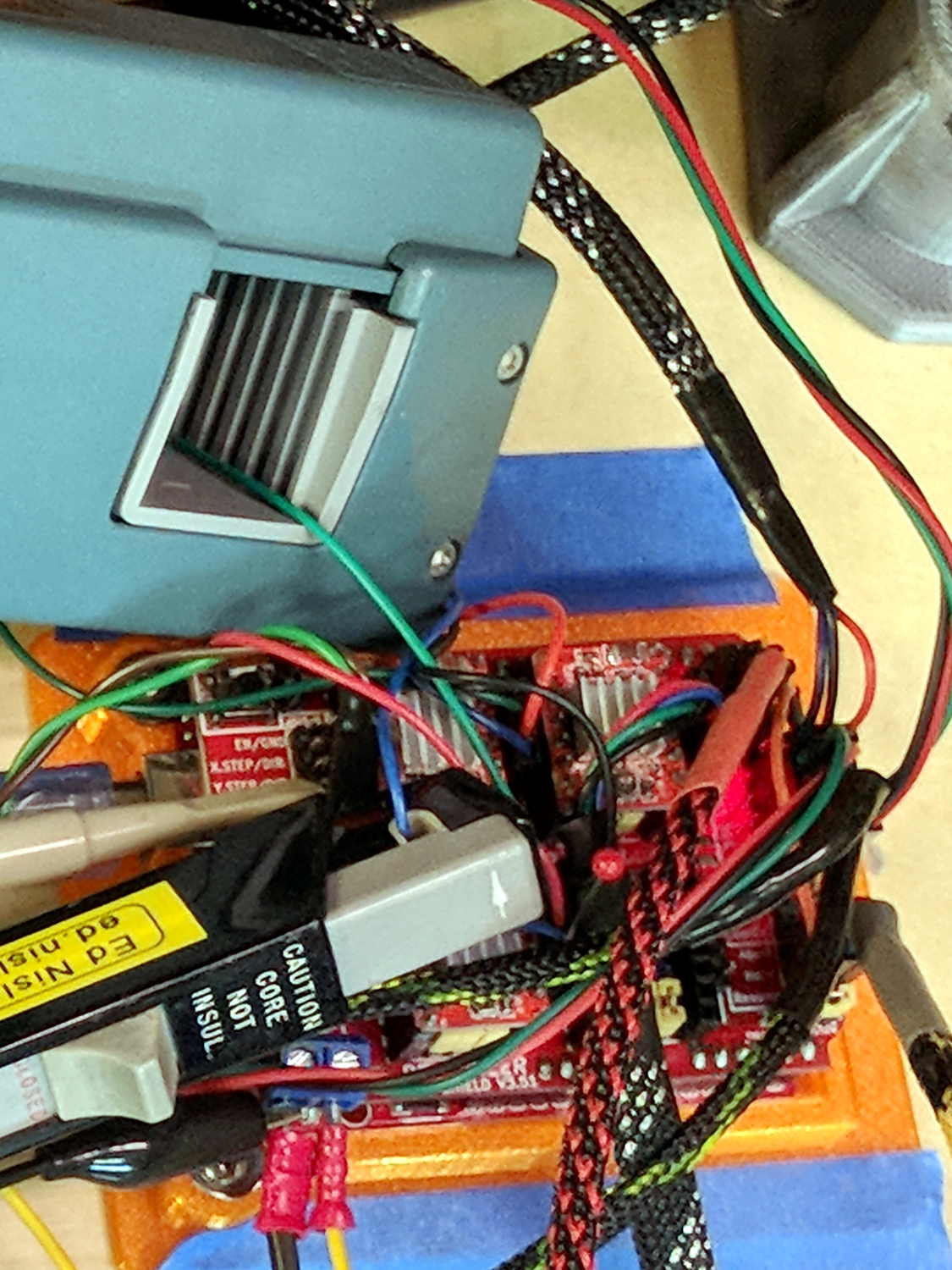
Just after that picture, I clipped off the NC switch terminal so I can wire this endstop in parallel with the tool length probe. Epoxy coating to follow.
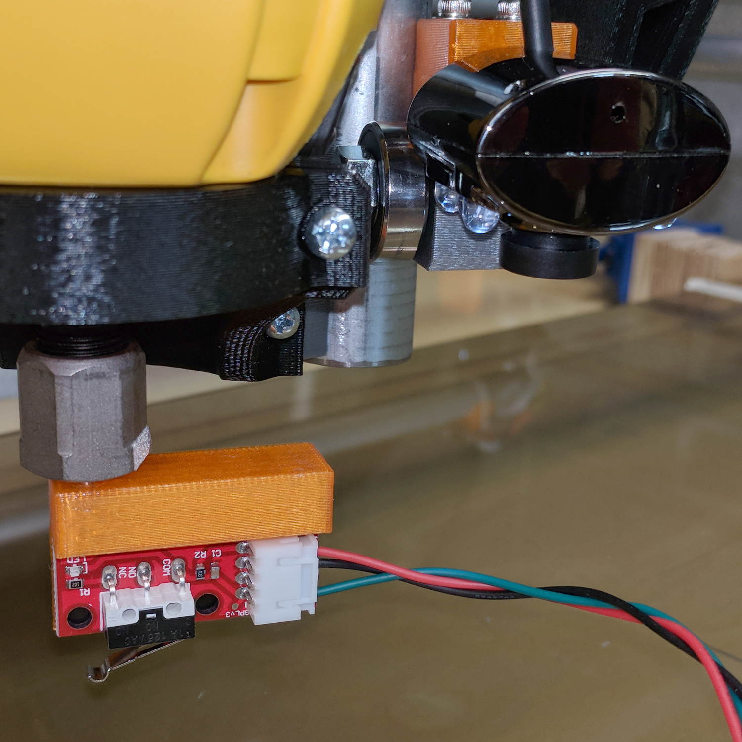
The DW660 collet grabs a length of 1/8 inch drill rod jammed into a hole positioned to put the switch actuator directly in line with the spindle axis when it trips the switch, so as to measure a known and useful location:
After mulling things over for a while, I fired up the Sherline, drilled a #54 hole in the actuator, and epoxied a 3/32 inch bearing ball in the hole:
A #54 drill hole is half the diameter of the ball and, with a bit of luck, enough of the ball will stick through into the epoxy on the underside for a good grip:
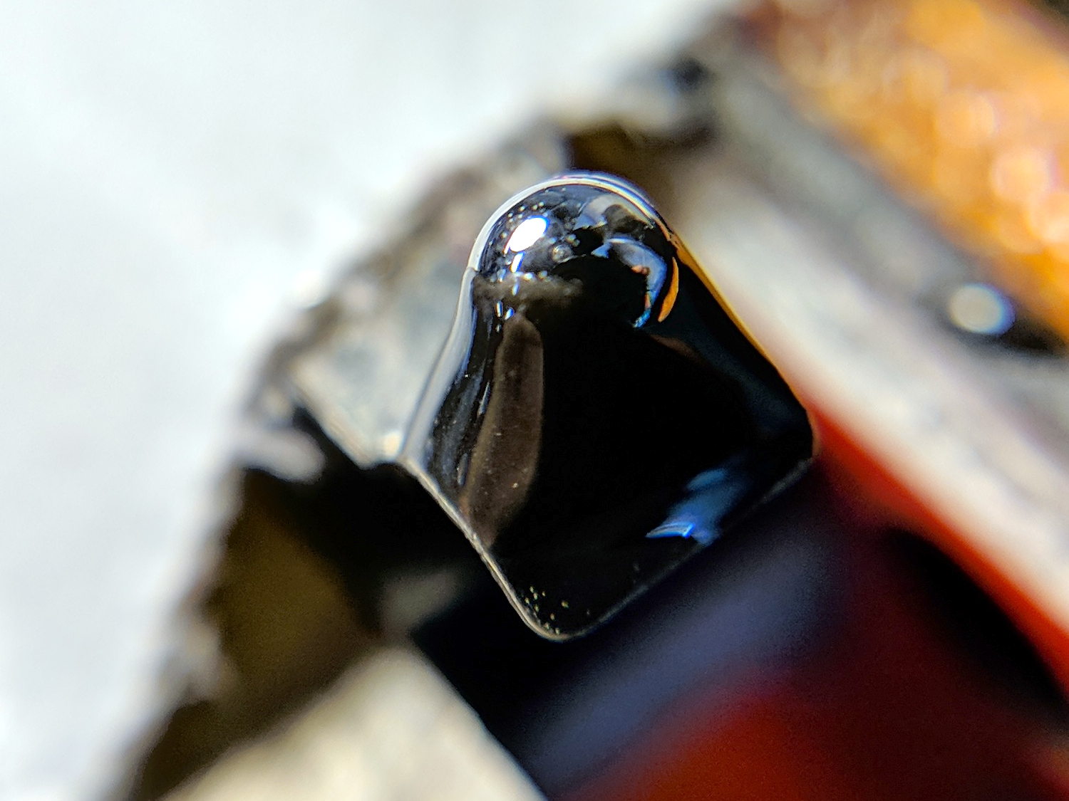
The general idea is to convert the stamped steel actuator into a single, albeit not particularly sharp, contact point that can glide over the platform / PCB / sheet-of-whatever to measure the surface. The actuator pivots as it depresses, so the ball must slide horizontally just a bit. I prefer a rod-in-tube probe poking a linear button switch, but those weren’t getting me anywhere.
If I were really cool, I’d use a ruby ball. Maybe silicon nitride?
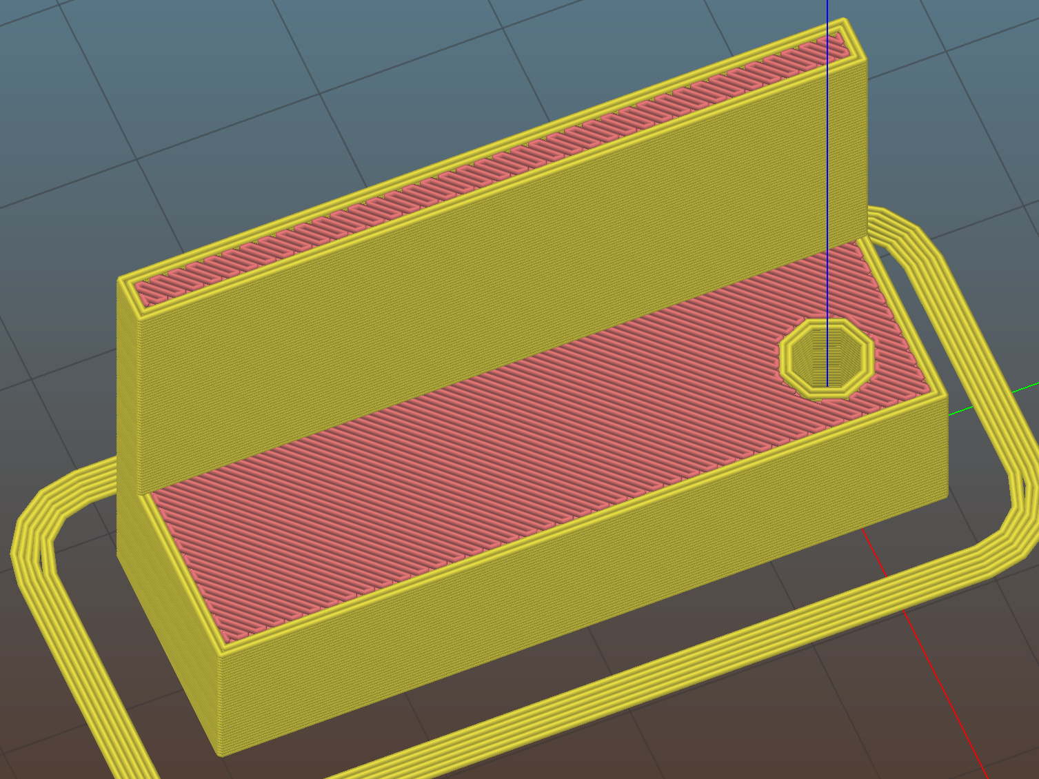
The OpenSCAD source code as a GitHub Gist:
| // MPCNC Z Axis Height Probe – MBI endstop in router collet | |
| // Ed Nisley KE4ZNU – 2018-02-17 | |
| Layout = "Build"; // Build, Show | |
| /* [Extrusion] */ | |
| ThreadThick = 0.25; // [0.20, 0.25] | |
| ThreadWidth = 0.40; // [0.40] | |
| /* [Hidden] */ | |
| Protrusion = 0.1; // [0.01, 0.1] | |
| HoleWindage = 0.2; | |
| inch = 25.4; | |
| function IntegerMultiple(Size,Unit) = Unit * ceil(Size / Unit); | |
| ID = 0; | |
| OD = 1; | |
| LENGTH = 2; | |
| //- Adjust hole diameter to make the size come out right | |
| module PolyCyl(Dia,Height,ForceSides=0) { // based on nophead's polyholes | |
| Sides = (ForceSides != 0) ? ForceSides : (ceil(Dia) + 2); | |
| FixDia = Dia / cos(180/Sides); | |
| cylinder(r=(FixDia + HoleWindage)/2,h=Height,$fn=Sides); | |
| } | |
| PCB = [40.0,1.6,16.5]; // endstop PCB, switch downward, facing parts | |
| Touchpoint = [4.8,4.8,-4.5]; // contact point from PCB edges, solder side | |
| TapeThick = 1.0; // foam mounting tape | |
| ShankOD = 0.125 * inch; // rod into tool collet | |
| ShankInsert = 3*ShankOD; // … insertion into switch holder | |
| WallThick = 3.0; // basic wall & floor thickness | |
| Mount = [PCB.x, | |
| (WallThick + TapeThick + Touchpoint.y) + (ShankOD/2 + WallThick), | |
| PCB.z + ShankInsert | |
| ]; | |
| NumSides = 2*4; | |
| //—– | |
| // Define shapes | |
| module SwitchMount() { | |
| difference() { | |
| translate([PCB.x/2 – Touchpoint.x, // overall block | |
| Mount.y/2 – (ShankOD/2 + WallThick), | |
| (PCB.z + ShankInsert)/2]) | |
| cube(Mount,center=true); | |
| translate([0,0,-Protrusion]) // collet shank hole | |
| PolyCyl(ShankOD,2*Mount.z,NumSides); | |
| translate([PCB.x/2 – Touchpoint.x, // PCB recess | |
| -Mount.y/2 + TapeThick + Touchpoint.y, | |
| PCB.z/2 – Protrusion/2]) | |
| cube([Mount.x + 2*Protrusion, | |
| Mount.y, | |
| PCB.z + Protrusion | |
| ] | |
| ,center=true); | |
| } | |
| } | |
| //—– | |
| // Build it | |
| if (Layout == "Show") | |
| SwitchMount(); | |
| if (Layout == "Build") { | |
| translate([0,0,Mount.z]) | |
| rotate([180,0,-90]) | |
| SwitchMount(); | |
| } |