Ed Nisley's Blog: Shop notes, electronics, firmware, machinery, 3D printing, laser cuttery, and curiosities. Contents: 100% human thinking, 0% AI slop.
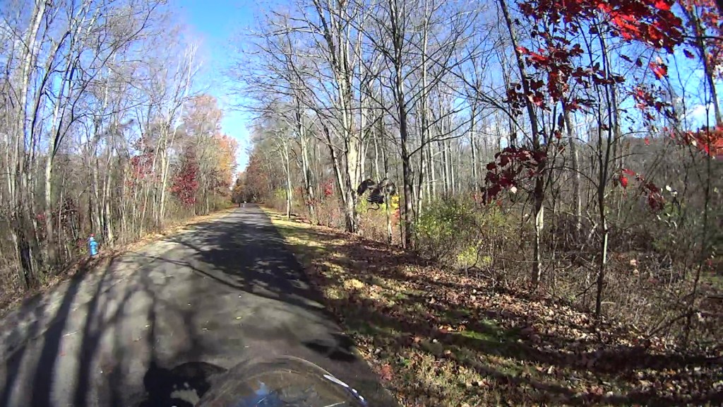
(The last three digits in the caption tick along at 60 frame/s. Opening each iamge in a new tab will let you embiggen the details, although the images aren’t all that great.)
The second wingbeat, over on the left, is more visible as the hawk lifts off:
Hawk with snake 2025-11-04 – 112
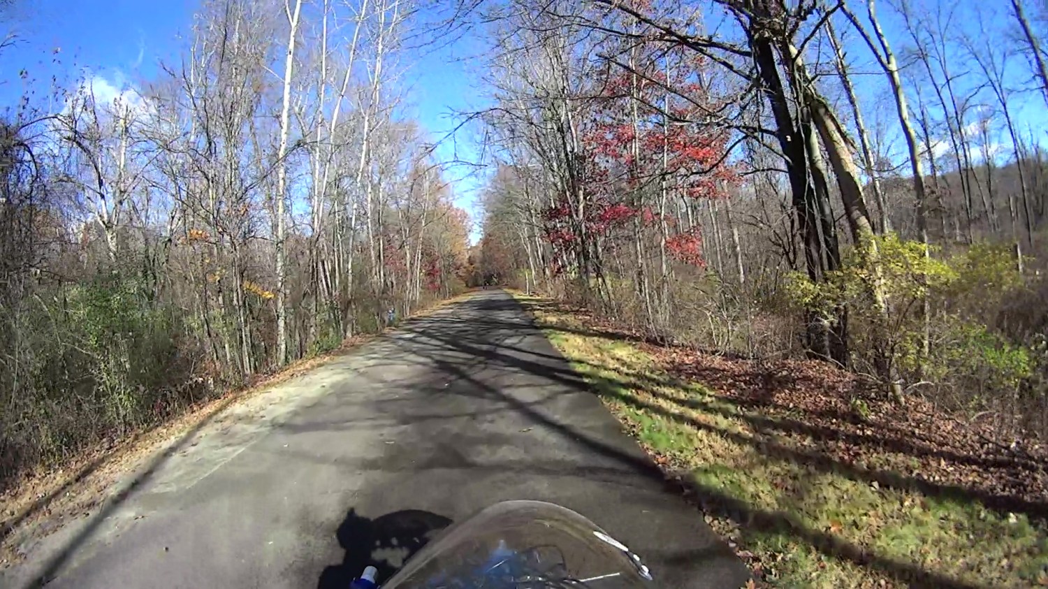
This was about when I figured out what was going on:
Hawk with snake 2025-11-04 – 151
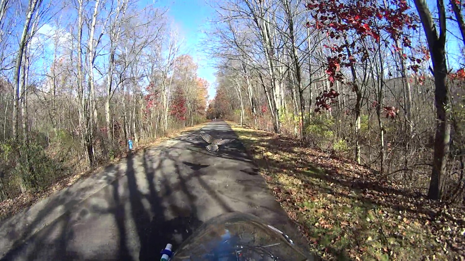
A hawk can easily outfly me!
Hawk with snake 2025-11-04 – 207
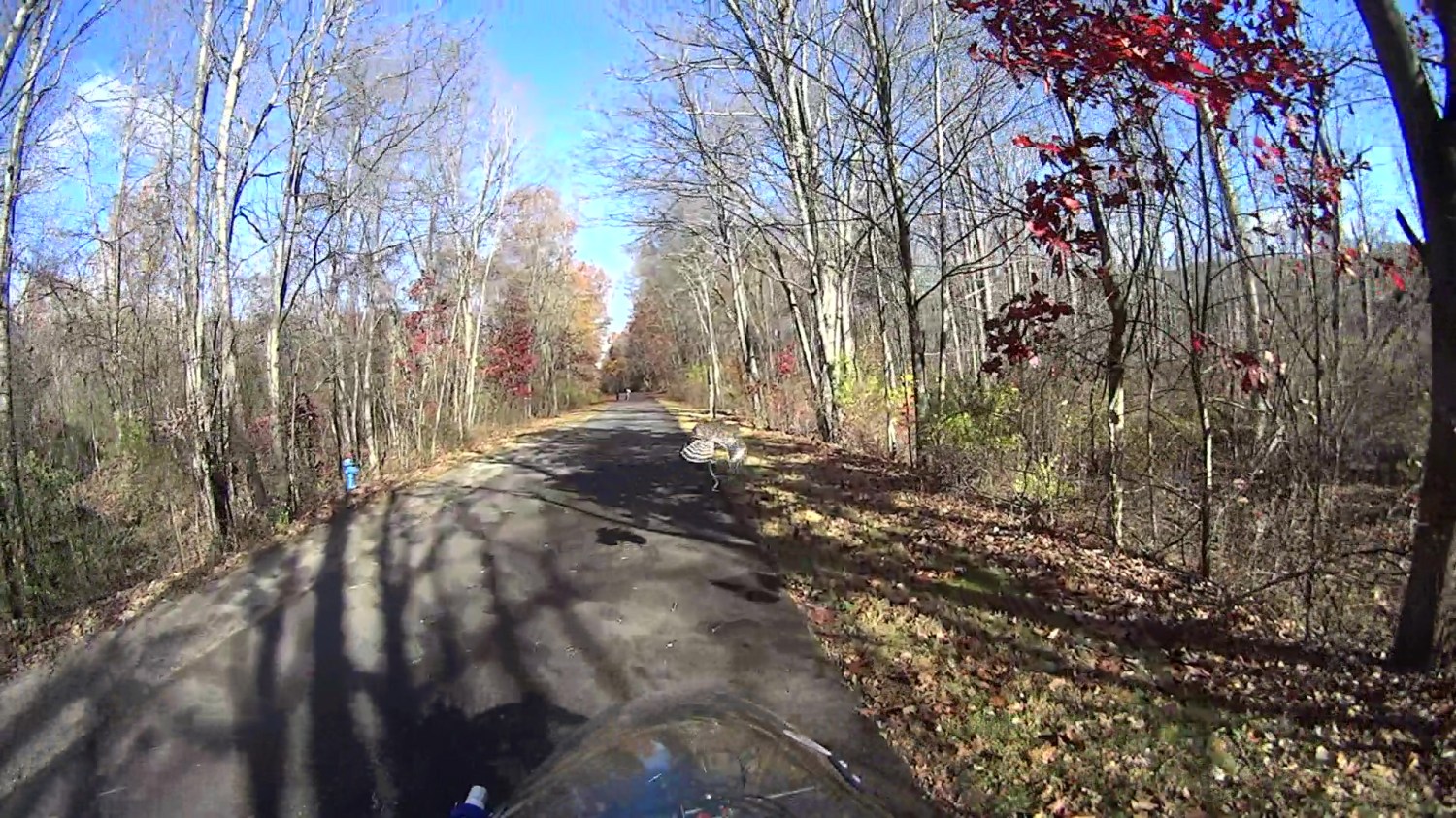
The snake dangling from the hawk’s talons didn’t see it coming, either:
Hawk with snake 2025-11-04 – 213
Up and away!
Hawk with snake 2025-11-04 – 225
About 2.3 s of elapsed time: plenty for a hawk and not nearly enough for me. Or the snake, for that matter.
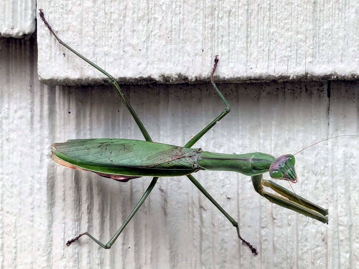
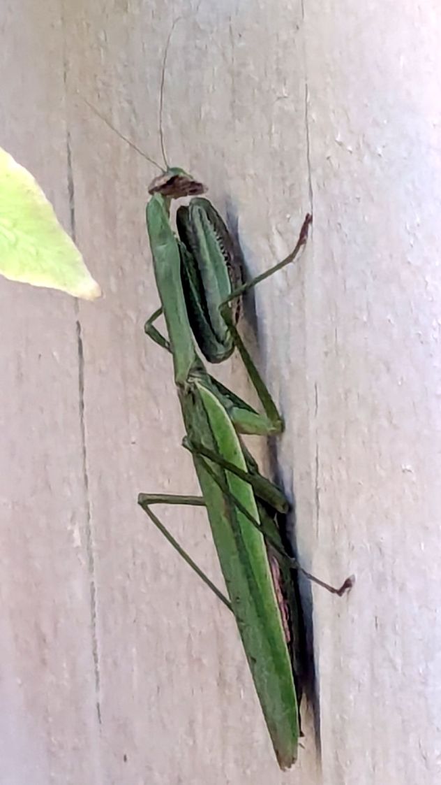
The next morning found it huddled against the cold:
Mantis – chilled
It had reached operating temperature and gone about its business a few hours later.
I deployed a cardboard Mantis in its honor as a seasonally appropriate yard decoration, but mine didn’t survive the night nearly as well as the real one:
I discovered this commentary, in several variations in different contexts, after attending the Poughkeepsie No Kings protest last weekend:
You are allowed to say, at any point, “I can’t support this”.
Even if you did.
Even if you were unsure.
You can say, at any point, “This has gone too far.”
And, while the best time to say that was earlier, the second best time is now.
That is relevant, because the Executive branch of the United States government has internalized two facts:
There are no rules
There are no consequences
The President and the Executive branch now act with the knowledge that the separation of powers, the checks and balances, and the restrictions written into the US Constitution no longer apply.
Justifications based on Constitutional hairsplitting are irrelevant. The Founding Fathers did not intend the Executive branch to operate as it does now.
Justifications based on “But what about …?” are irrelevant. The scale of current malfeasance dwarfs all precedent; there are no valid comparisons.
Justifications based on “But Congress is dysfunctional!” are irrelevant. It takes only one to dysfunction and the parties have been swapping irresponsibility for decades.
I commend to your attention the Army Talk Orientation Fact Sheet 64 from March 1945. It is straight-up US WWII propaganda with a rosy view of the Soviet Union, but you should fact-check all items in the section “Can We Spot It?” on page 4 against current events.
Should you think your particular identity, institution, tradition, behavior, property, possessions, protection, legality, or beliefs will remain untouched because you’re in a particular group, you are incorrect.
I changed my voter registration to “No Party” several decades ago, when it became evident the Republican Party had lost interest in whatever small-government / low-deficit / personal-responsibility principles it may have once had; thinking it had those principles was likely a misunderstanding on my part.
I cannot support many planks of the Democratic Party’s platform, either, but they remain based in rule-of-law and have some appreciation of what functions a government should perform.
I still vote in every election and intend to continue doing so.
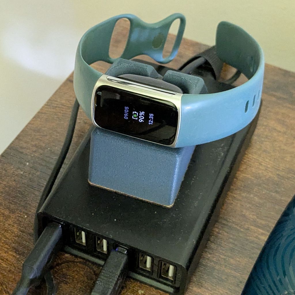
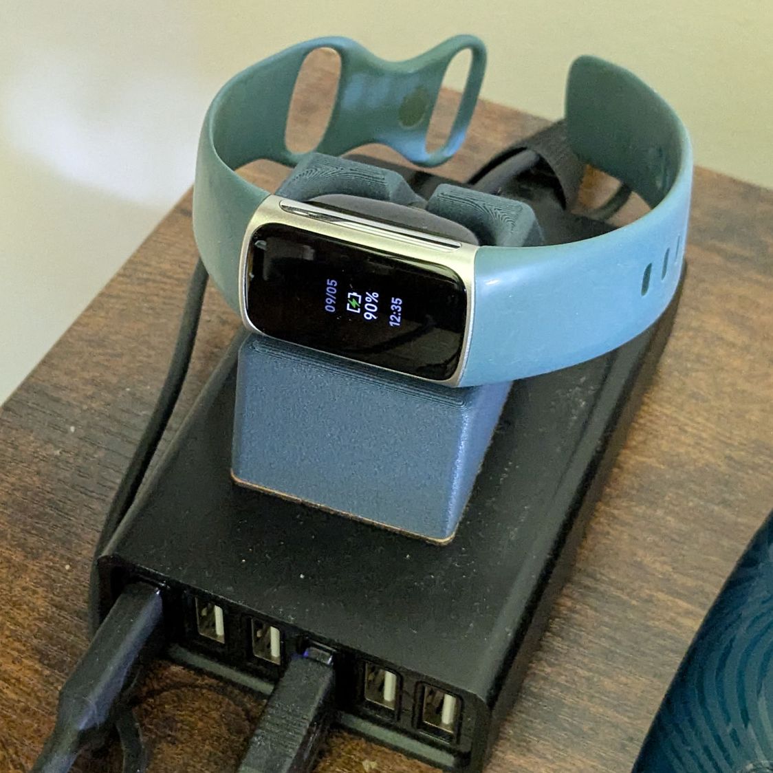
WordPress likes images and this seems appropriate:
My Fitbit Charge 5 exercise tracker estimates my VO2Max as somewhere between 51 and 55. That seems absurd for a guy of my age, where “Excellent” is a bit under 40. I am most certainly not a highly trained athlete at the top of my form, so I wondered what the real value might be.
It also computes my maximum heart rate from my age as 220 – 72 = 148, much lower than the values I routinely see while biking around the area. Reviewing a few months of data suggests an actual value around 170, although I did see 185 on one occasion.
Forcing a maximum heart rate of 170 changed the VO2Max estimate to 50-54, which still seemed absurdly high. At least that change made the Fitbit’s “heart rate zones” a little more reasonable, as ordinary bike rides no longer have me in the Peak zone nearly as often.
The Rockport walking test calculates VO2Max from a timed walk over a one mile “track” course, so I laid out a half-mile out-and-back route on Zack’s Way, which is a quarter mile from home.
Maintaining a brisk pace covered the mile in 15:49 and left me with a 110 pulse; it’s obvious I’m not a trained athete. Feeding those numbers and a few other vital details into the Rockport formula gives me a much more realistic VO2Max of 28.5, putting me somewhere between the 50th and 75th percentile.
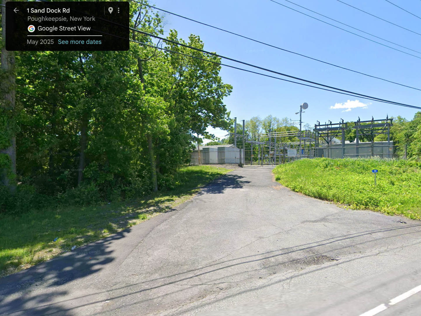
For reasons not relevant here, I walked along IBM Rd to the end of Sand Dock Rd and back, passing the switchyard serving the IBM Poughkeepsie site:
Street View – 1 Sand Dock Rd
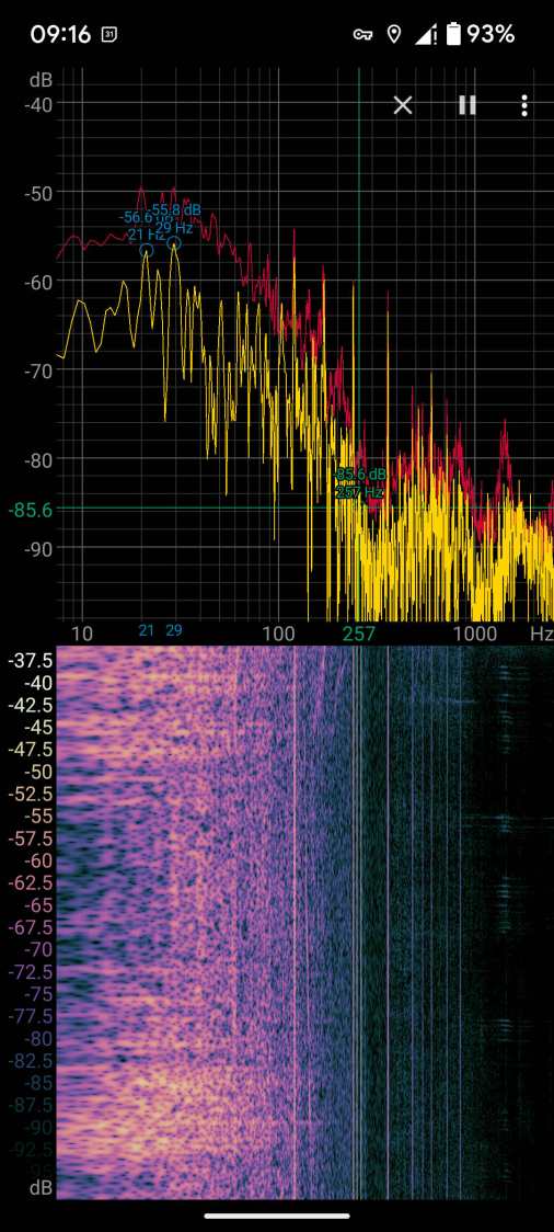
The overall capacity is surely in the tens of megawatts and there’s an overwhelming hum coming down that driveway:
Switchyard hum
Those peaks and the corresponding lines in the waterfall show the equipment emits acoustic energy all the way up to about 480 Hz, call it the eighth harmonic of 60 Hz.
Transformer steel has low magnetostriction, which produces most of the noise at even harmonics of the 60 Hz power line (because each cycle has two current maxima). The spectrogram shows the switchyard handles enough current to emit plenty of odd harmonic energy, with a notable peak at 180 Hz.
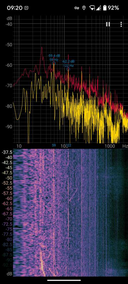
For comparison, standing a few feet from the transformer behind a medical office building along IBM Rd:
Transformer hum
No 180 Hz energy from that transformer!
Moving a few feet further away dropped those peaks into the background.
Even with my deflicted ears, I think can hear the switchyard hum from a considerable distance along the road, so maybe the background isn’t as quiet as I think.
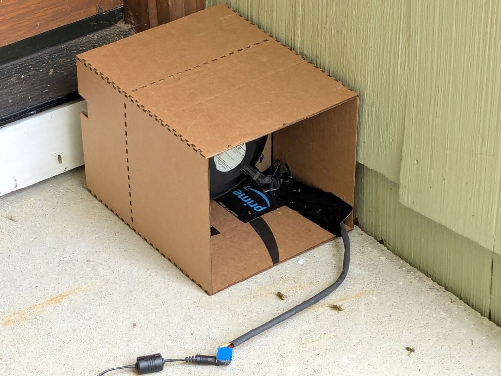
A colony of Yellowjacket wasps moved into a gap somewhere inside our front door, which we noticed only after they set up a heavy traffic pattern over the front step. The nest is far enough up inside the door frame (or, shudder, the wall) to be immune to rattlecan insecticide spray and the wasps simply tiptoe across sticky-trap sheets laid on their entrance paths.
That’s a hulking 12 V electronics case fan mounted on a cardboard bulkhead inside what’s basically a tunnel, with its power supply plugged into a widowmaker extension cord screwed into the light fixture next to the door.
The fan blows away from the door, with the general idea of killing wasps leaving the nest. Arriving wasps can walk home around the box, but departing wasps always take flight from the small crack under the door sill, whereupon they’re sucked into the fan, shattered by the blades, and blown out onto the step.
A Yellowjacket can make headway into a 1 m/s wind, but not for very long, which explains why most of them prefer walking home.
The carnage looks awful, so it seems to be working …
Spotted on the way around one of the myriad strip malls (different from “strip clubs“) sporting a “Recently Renovated” sign out front:
Renovations – overpainted sign
You just know what those signs said, right? Must not be important any more.
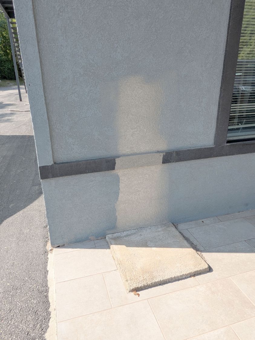
Around the corner, the painters couldn’t get to where they needed to go:
Renovations – paint underspray
A Streetview image from seven years back tells the tale:
Renovations – Street View 2018
So the most generous interpretation would be something like overspraying those signs was a mercy killing. I’m impressed they could get that much paint behind the UPS drop box!
Out front there’s another triumph of hope over experience: