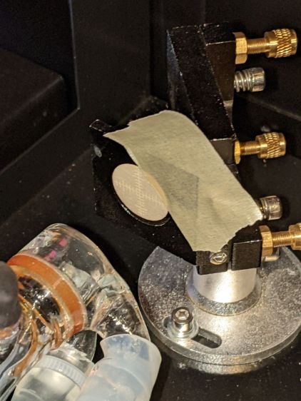
The canonical beam alignment target seems to involve tape stuck on the mirror bracket:
With a full-power beam burned through it:
The roll of “white masking tape” supplied by OMTech turned out to be knockoff tapeless sticky adhesive film. After sticking a length to the mirror bracket, the white backing tape peels right off, leaving the adhesive film stuck to the bracket. Well, my tapeless sticky roll was running low, so this roll won’t go to waste.
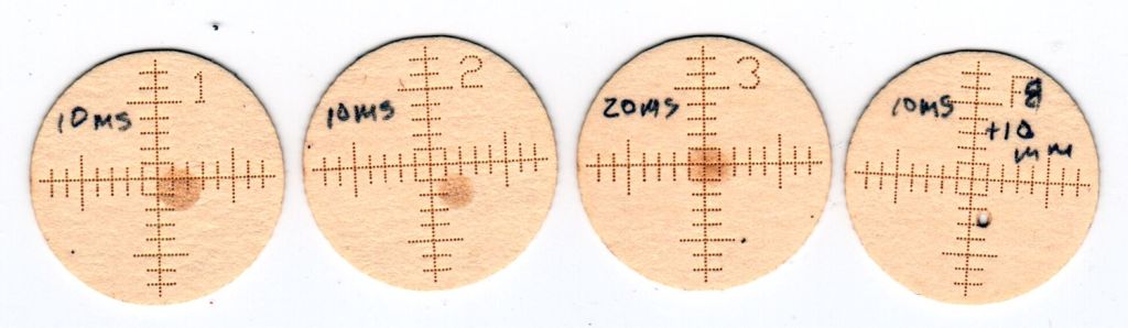
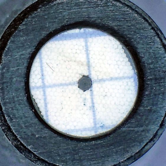
A laser cutter can make intricate paper doodads, so I conjured better targets from the Vasty Digital Deep:

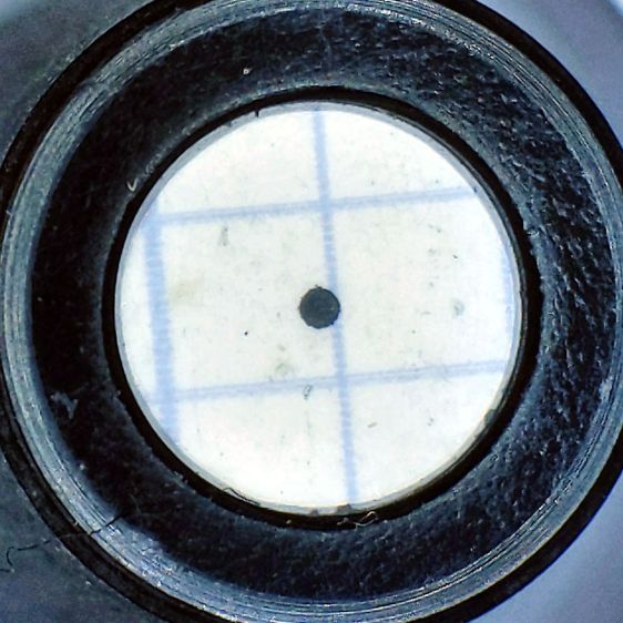
They’re burned into an ordinary manila file folder in “dot mode”: 2 ms pulses at 30% power separated by 0.25 mm. The 1 mm graticule locates the beam relative to the center, which is pretty close to the actual center of the opening, because the outer 17 mm cut fits neatly into the 17.5 mm hole. The label tells you where it goes and which line should point up.
Your mileage will vary, but the general idea is to have a disk held in place by actual masking tape:
Admittedly, orienting the graticule requires a bit of dexterity, but getting it pretty close is pretty easy.
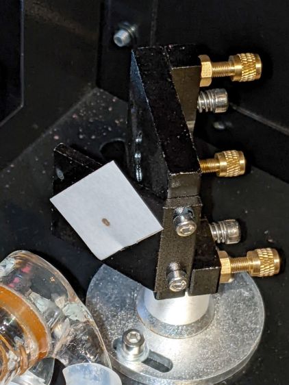
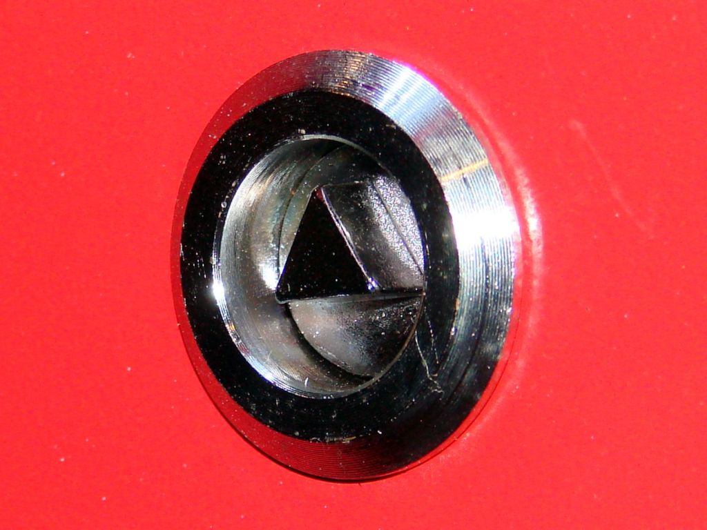
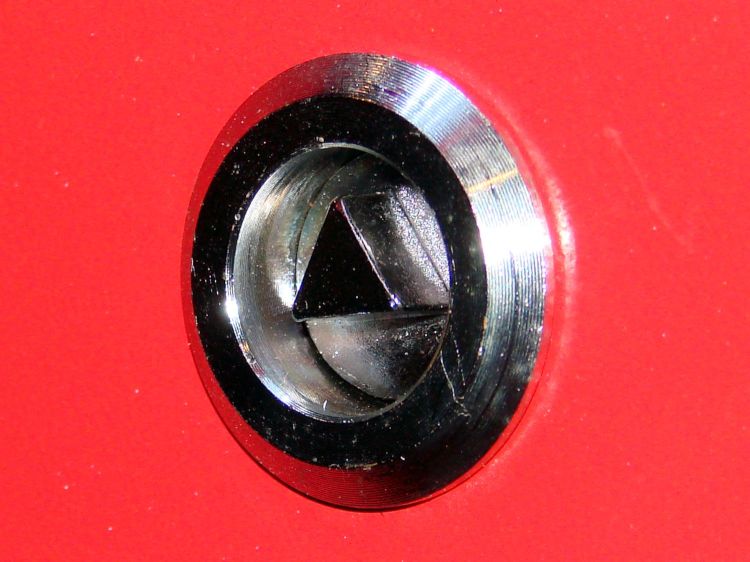
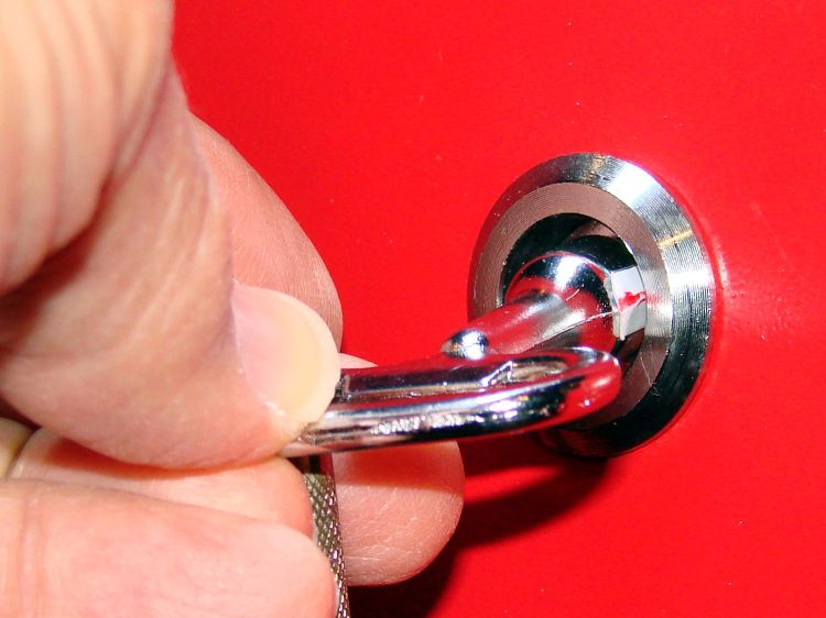
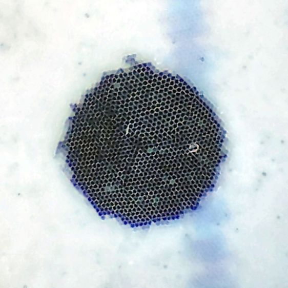
Set the laser to fire a single 10 ms pulse when you press the front-panel button, thereby toasting a spot at the most intense part of the beam:

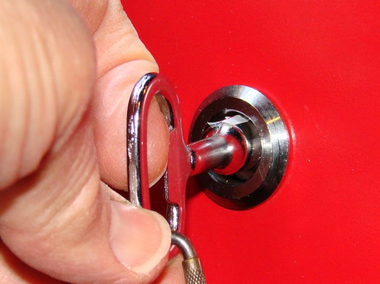
Repeat to record the beam position at all three mirrors:

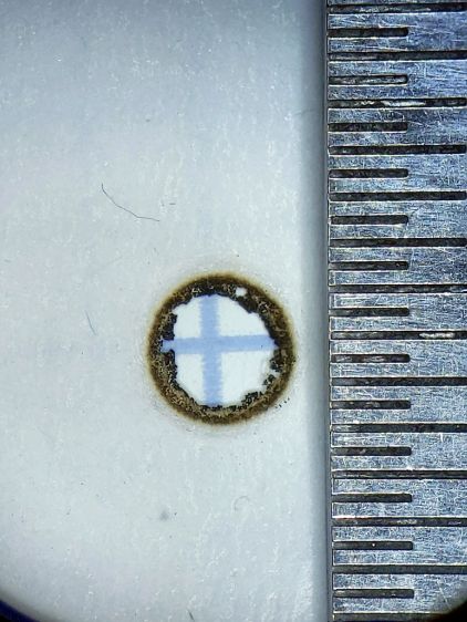
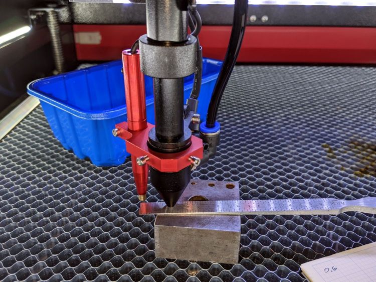
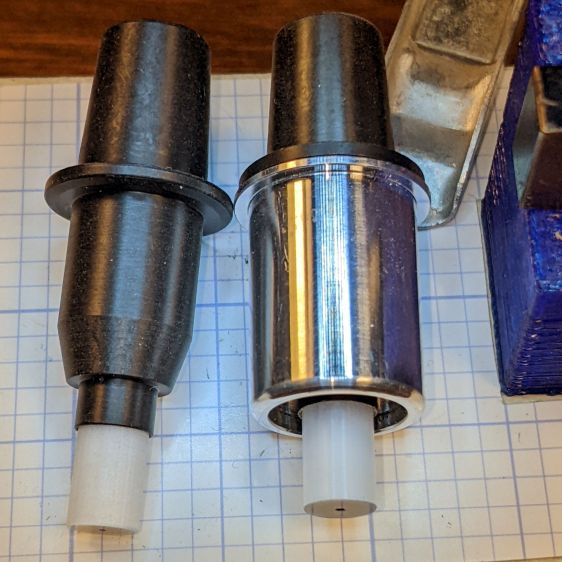
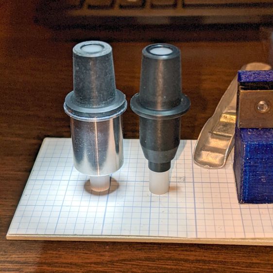
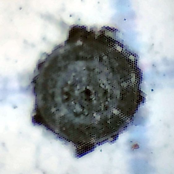
The focal point target serves to verify the focused beam size and its alignment with respect to the aiming laser spot:

That target came from a scrap of cardboard while I was figuring out how to make the things.
All in all, OMTech did a pretty good job of aligning the beam, although the red laser dot needed a nudge. Now I have a record of where the beam was before I mess with clean the mirrors and lenses.
The SVG image as a GitHub Gist:


