Ed Nisley's Blog: Shop notes, electronics, firmware, machinery, 3D printing, laser cuttery, and curiosities. Contents: 100% human thinking, 0% AI slop.
The little DSO-150 oscilloscope has a 1 MΩ || 20 pF input with a 200 kHz bandwidth that should be entirely adequate for the OMTech laser’s millisecond-scale modulation signals from the Gentec ED-200 Optical Joulemeter. There is, however, only one way to be sure:
Gentec ED-200 – scope test setup
The two scope inputs are in parallel, so the joulemeter over on the far right sees a 500 kΩ load, half of the specified 1 MΩ load, with at least twice the capacitance. If the two scopes display pretty much the same result, then it’s good enough.
A 50 ms pulse at half power looks the same on both scopes:
Gentec ED-200 – 50 ms – DSO-150
Gentec ED-200 – 50 ms – Siglent
A 50 ms pulse at full power doesn’t quite top out:
Gentec ED-200 – 11V 50ms – DSO-150
Gentec ED-200 – 11V 50ms – Siglent
Given that the pulse duration should be less than the detector’s 1.5 ms risetime, using a 50 ms pulse is absurd. Right now I’m just looking at the overall waveform and detector range, not trying to get useful numbers out of the poor thing.
The Gentec ED-200 Joulemeter is severely underqualified to measure the OMTech 60 W laser’s beam power, because the laser’s 1 ms minimum manual pulse width isn’t much shorter than the sensor’s 1.5 ms risetime and the maximum beam power is far too high for the sensor’s health. With that in mind, I set the PWM power to 50% = 30 W (grossly too high) and looked at the peak output voltage for a series of (far too long) pulse widths:
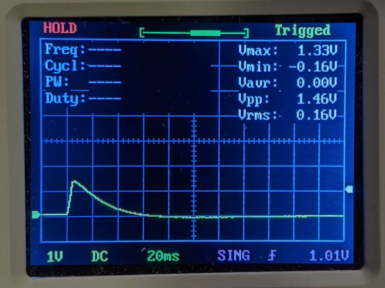
Rounding the detector sensitivity to 11 V/J says the 1.3 V peak at 5 ms corresponds to 120 mJ and 24 W:
Gentec ED-200 – 60W 50pct 5ms
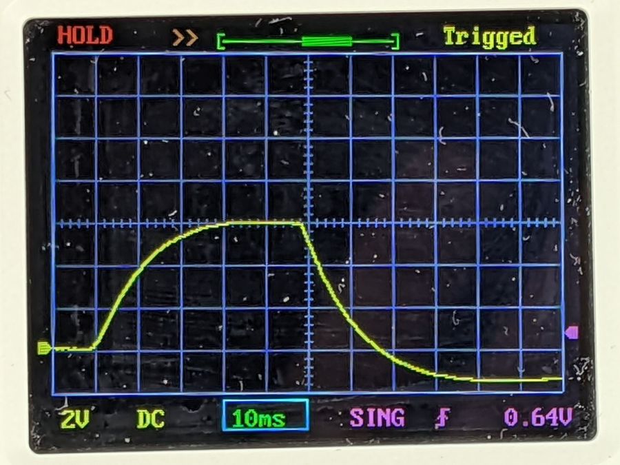
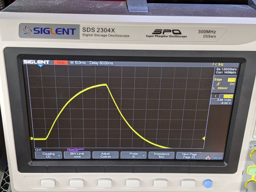
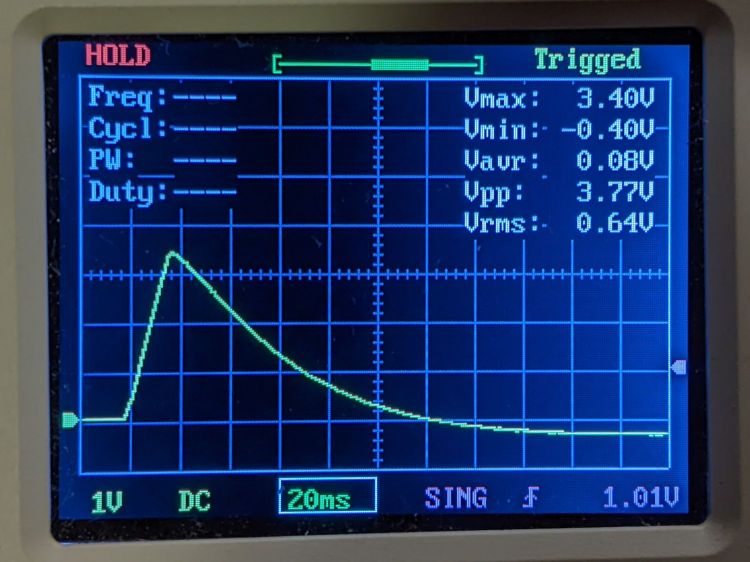
The 3.3 V peak at 10 ms is 300 mJ and 30 W:
Gentec ED-200 – 60W 50pct 10ms
The 3.4 V peak at 15 ms is 310 mJ and 21 W suggests the PWM power output is not nearly as constant as one might expect, although the pulse width looks fine:
Gentec ED-200 – 60W 50pct 15ms
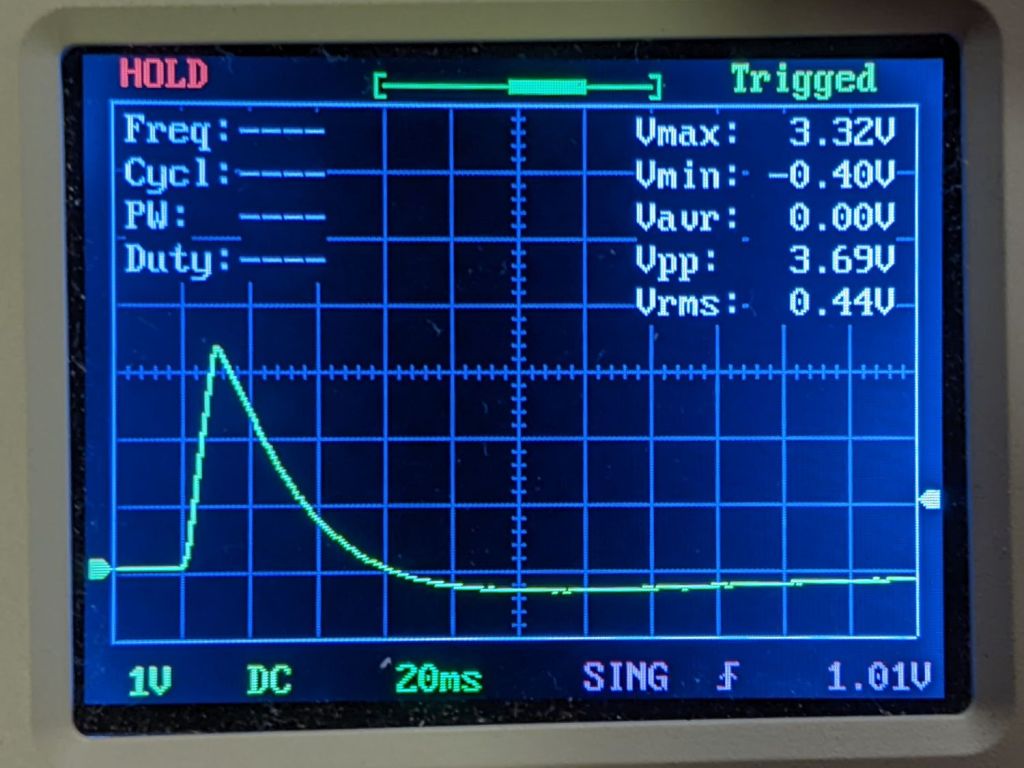
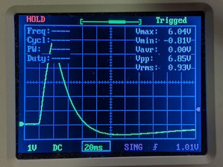
The 6 V peak at 20 ms is 550 mJ and 27 W, although the on-screen display obscures the top:
Gentec ED-200 – 60W 50pct 20ms OSD
Another 20 ms pulse without the OSD produces a peak eyballometrically close to 6.4 V for 580 mJ and 29 W:
Gentec ED-200 – 60W 50pct 20ms
The KT332N controller in the OMTech 60 W laser has a pulse duration setting showing tenths of a millisecond, but (based on some additional measurements) the beam power can vary by 25% for successive pulses in the low millisecond range, so the pulse width resolution doesn’t seem to provide useful control.
Despite the over-long pulses, the calculated power corresponds surprisingly well with the nominal laser output power.
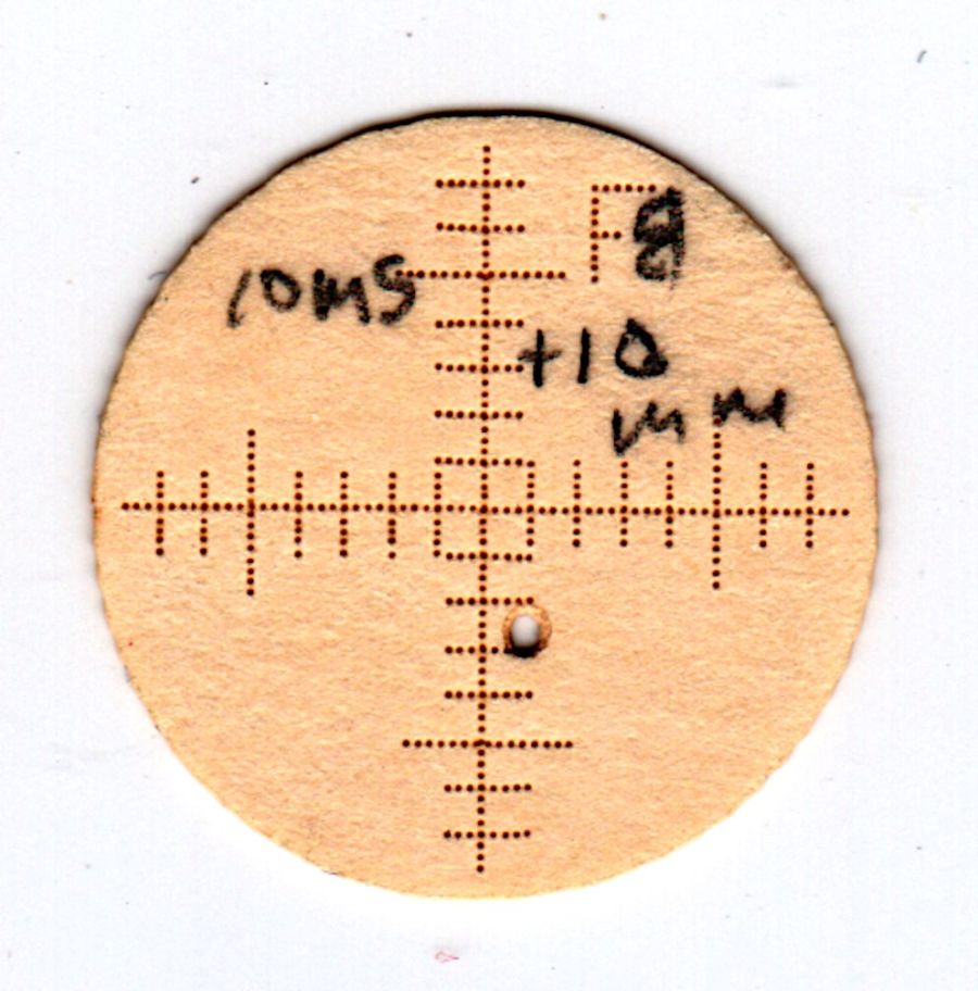
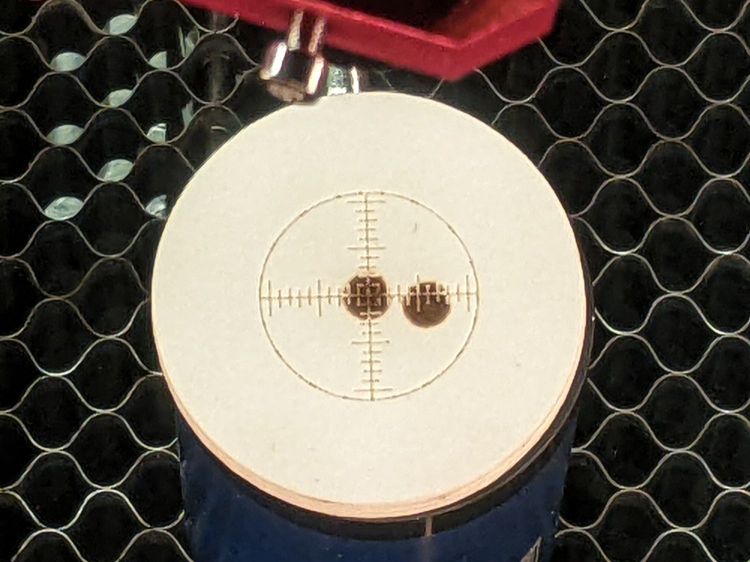
The 1 ms pulses used in LightBurn’s Dot Mode are consistent enough to punch essentially identical 0.2(-ish) mm holes in manila paper to mark the graticule:
They’re on 0.25 mm centers, with slight variations showing the difference between stepper resolution and positioning accuracy. The shorter graticule lines have three holes on one side of the center lines and four on the other, despite the design’s 1 mm length on both sides; I think there’s a missing dot on the side where the head starts the line, perhaps due to a picket-fence error.
The large beam hole came from two 10 ms pulses, one at the focal point and another 10 mm lower.
During the last snowstorm of the season, the venerable MTD snowthrower carved a trench out of the garage and across the driveway, then abruptly stopped moving. The motor roared and the auger turned, but the drive clutch handle had no effect, so I dragged its carcass into the garage and we completed the mission by hand.
Popping the belly plate on the next sunny day revealed the problem: the jam nut (part 34) anchoring the Friction Disk Wheel (part 28) to the Friction Wheel Bracket Assembly (part 32) had gone missing:
MTD Snowblower – page 26 – friction drive parts
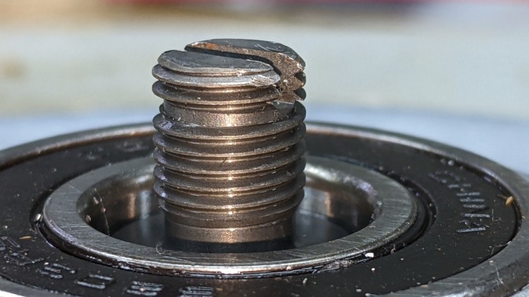
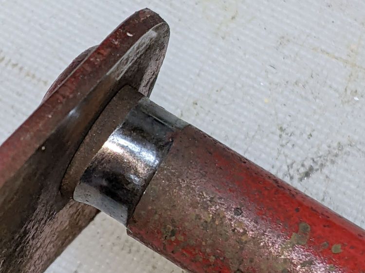
Worse, the Wheel’s threaded shaft spent some time rattling around in the Bracket while chewing up its thread:
MTD Snowthrower – friction disk wheel – damaged thread
This would ordinarily be No Big Deal, but what you see of the shaft is all you get: it rotates freely in the bearing embedded in the Wheel with no way to hold it while cleaning up its threads.
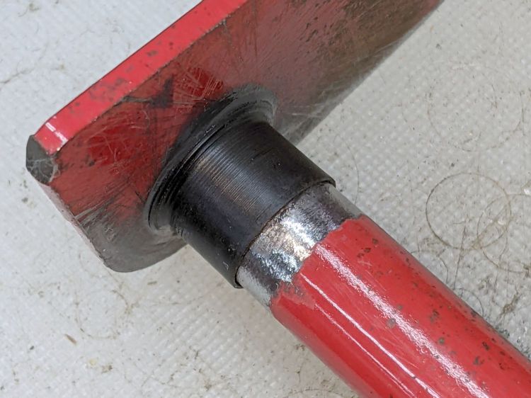
Having already promised to replace the Wheel, I installed the new Wheel using a castle nut secured with a generous dollop of red Loctite, then tapped two of its castellations into the shaft’s slot as a mechanical anchor:
MTD Snowthrower – friction disk wheel – castle nut
I really wanted to lay a nice hard roll pin along that slot through the nut, but there’s no convincing way to secure such a thing without a second nut. Maybe next time?
While I had the drive train apart, the sad state of the Wheel Shift Rod Assembly (part 29) became apparent:
MTD Snowthrower – wheel shift rod – worn
I scuffed up the shiny wear mark, turned a suitable acetal bushing, filled the trench with epoxy, and squished the bushing in place:
MTD Snowthrower – wheel shift rod – acetal bushing
The flange might hold it in place against the Frame Shift Bracket (part 18), which snugly contains the rest of the bushing against the epoxy, so the whole affair might outlast the next season’s first snowstorm. We shall see.
The Max Energy Density spec suggests longer pulses are allowed to deposit more energy, probably because more time gives thermal diffusion an opportunity to spread the heat across the target; at CO₂ laser wavelengths that may not apply.
With the platform lowered as far as it goes, the ED-200 is 130 mm below the laser nozzle where the beam diameter is about 6 mm for an area of 0.3 cm². Ignoring the ideal Gaussian beam profile by smearing 60 W uniformly across the circle gives a power density of 200 W/cm², which means the laser pulse must be less than 0.5 W·s / 200 W = 2.5 ms to stay inside the power density limit.
I sincerely hope Gentec overbuilt and underspecified their detector.
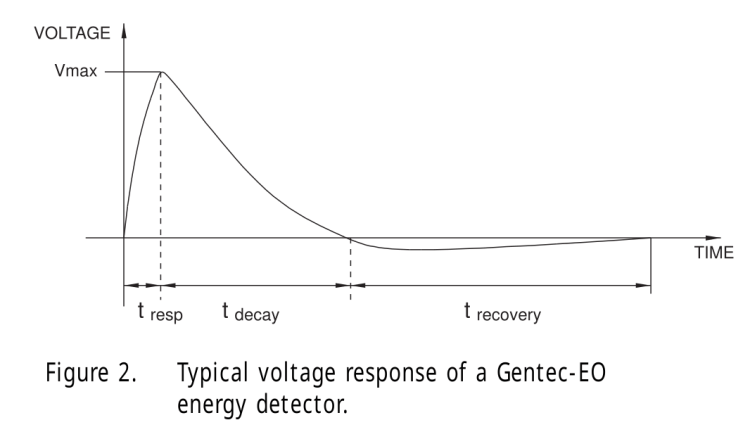
The Voltage Response The result is a voltage pulse that rises quickly with the response time of the device to a level proportional to the laser energy (Figure 2). It then decays exponentially over a longer period of time that is a function of the pyroelectric device and load impedance. Figure 2 also shows that there is a longer recovery time to return to the initial state of the detector. This is a function of thermal phenomena and is not affected by the load impedance as are the rise and decay times. The integrated pulse energy over this period is proportional to the peak voltage.
Pulse Width Versus Rise Time
Usually the applied laser pulse must be shorter than the rise time of the detector for all of its energy to be represented by the peak voltage. Pulse energy received after the detector voltage has peaked will not be fully integrated into that value. For very long pulses, the peak voltage will actually represent peak power rather than pulse energy.
Gentec Energy Detectors, page 2
Figure 2 shows the overall waveform:
Gentec Energy Detectors – Figure 2
Which looks a lot like this 10 ms pulse at 50% duty cycle:
Gentec ED-200 – 60W 50pct 10ms
The pulse was 10 ms long, much longer than the 1.5 ms ED-200 risetime spec, but the overall shape looks right. Dividing the 3.3 V peak by the detector’s 10.78 J/V calibration value (11 J/V works for me) says the pulse delivered 300 mJ = 300 mW·s. Dividing 300 mJ by 10 ms gives 30 W, a beam power astonishingly close to the expected value.
The OMTech laser has a nominal 60 W output, although the tube life drops dramatically with regular use over 70% = 40 W. Power does not scale linearly with the laser tube current displayed on the power supply milliammeter, with the maximum value presumably preset to the tube’s 20 mA limit producing 60 W. The 20 kHz PWM duty-cycle chopping applied by the controller should linearly scale the average power downward from there.
It looks like the ED-200 might deliver reasonable results for millisecond-scale pulses at low PWM duty cycles, but it was obviously intended for much milder lasers.
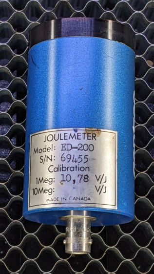
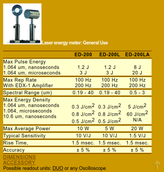
The Box o’ Optical Stuff disgorged an ancient Gentec ED-200 Joulemeter:
Gentec ED-200 – measurement setup
It’s an optical pyrometer producing, sayeth the dataplate, an output of 10.78 V per joule of energy applied to its matte black absorber. Whether it’s accurate or not, I have no way of knowing, but aiming the business end toward the sun and waving my fingers over it produced a varying voltage, so there was hope.
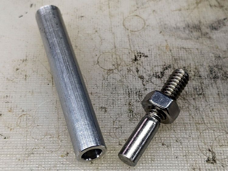
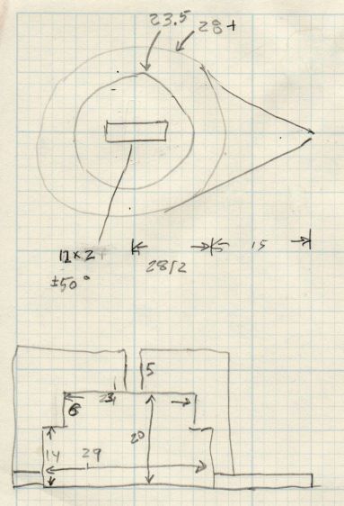
It has a 1/4-20 socket on one side and my spare magnetic mount expects a 3/8 inch rod, so I drilled a suitable hole in a suitable aluminum rod and cut the head off a suitable bolt:
Gentec ED-200 mounting rod – parts
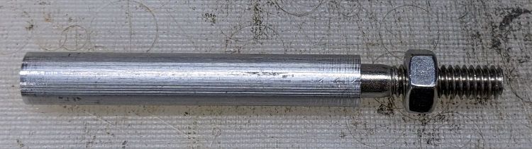
A dab of Loctite intended to secure bushings completed the assembly:
Gentec ED-200 mounting rod – assembled
I later replaced the nut with a finger-friendly nylon wingnut.
Which allows a measurement setup along these lines:
Gentec ED-200 – measurement setup
The white disk atop the sensor is a homebrewed target to indicate the active sensor area and its center point:
Gentec ED-200 target – scorches
The 1 mm graticule lines give a jogging suggestion to hit the center, assuming you (well, I) manage to hit anywhere on the target at the first shot. The beam is supposed to fill most of the central region, which is obviously not going to happen here, and it must not be focused to a pinpoint. The previous owner (or his minions) put a few scars on the surface and I expect to make similar mistakes.
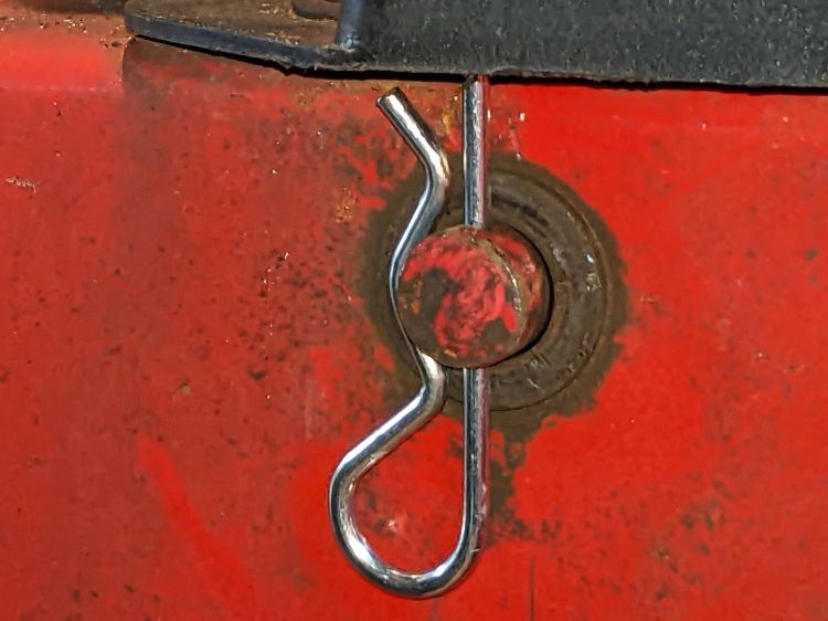
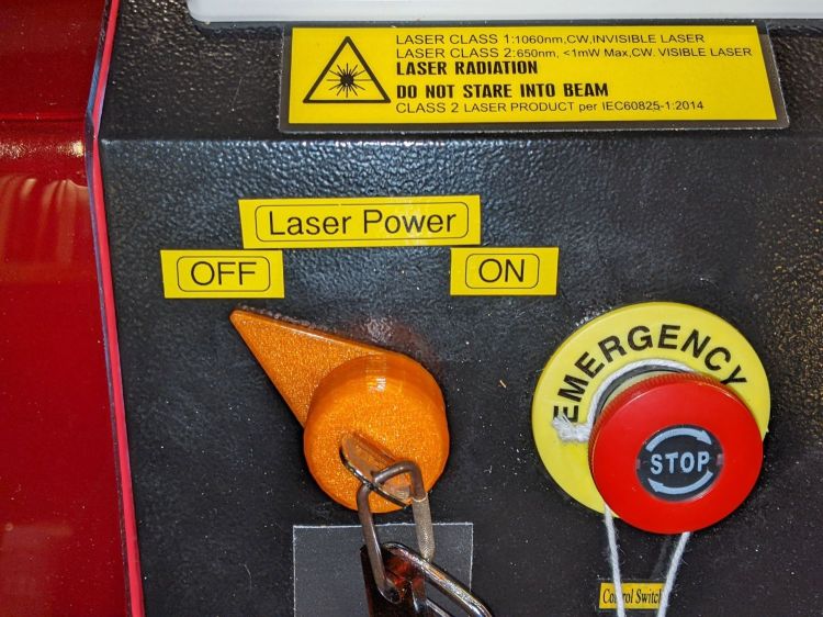
Although the OMTech laser controls the laser power supply with a key-lock switch, there’s little visible difference between the OFF and ON positions. Having occasionally mistaken it in both directions, this seemed like a useful addition:
Laser Power Lock Indicator – installed
The strip of black duct tape below the lock muffles the rattle of the triangle hatch key against the metal cabinet.
Two snippets of foam tape hold the knob to the lock cylinder, making an admittedly tenuous connection, but the knob fits around the outside of the switch housing with minimal clearance and doesn’t shouldn’t suffer any torque or pulling, so it might work.
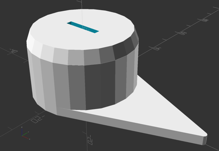
The solid model looks about like you’d expect:
Laser Power Lock Indicator – solid model
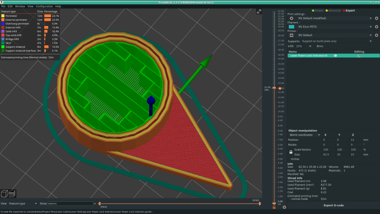
Unfortunately, it has no good orientation for printing, so I let PrusaSlicer generate support material inside the knob:
Laser Power Lock Indicator – Support structures
Suffice it to say: removing all that plastic did not go well.
I eventually grabbed the knob in the lathe and bored the interior out to its more-or-less proper dimensions, figuring nobody would ever notice the carnage, and it worked reasonably well. In the unlikely event I need another pointer, I’ll add a support spider to hold up the interior with minimal contact and less plastic.
Yeah, the laser really needs a stack light showing its condition and safety status …
This file contains hidden or bidirectional Unicode text that may be interpreted or compiled differently than what appears below. To review, open the file in an editor that reveals hidden Unicode characters.
Learn more about bidirectional Unicode characters
It’s stuck to the lip inside the top hatch on the right side of the cabinet, which may not be the most convenient location, but keeps it out of the way and doesn’t require much additional tubing.
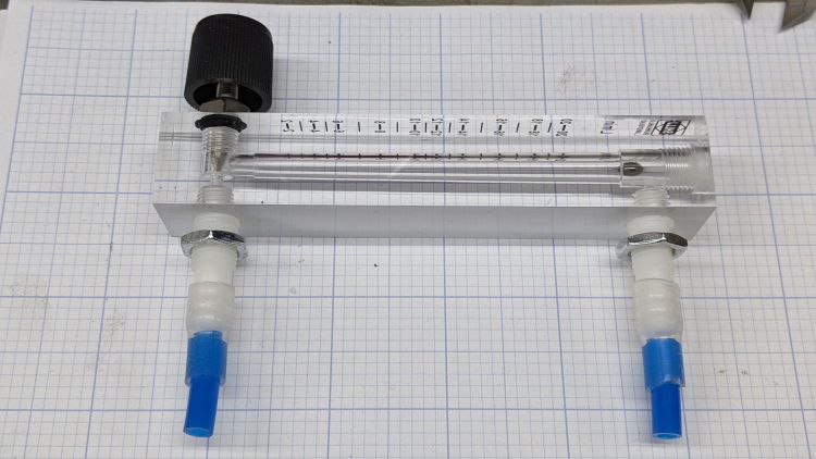
The 6 mm tube kit included some (1/8 NPT?) push fittings that came heartbreakingly close to matching the flowmeter’s internal threads:
OMTech Laser – air flowmeter – push tube fittings
Given that the air pump doesn’t produce much pressure, two snippets of 1/4 inch silicone tubing suffice to couple the blue 6 mm tubing to the flowmeter’s barbs:
OMTech Laser – air flowmeter – silicone tube adapter
The run from the air pump to the flowmeter is now new blue tubing, with the original black tubing running through the drag chain to the laser nozzle:
OMTech Laser – air flowmeter – tube layout
Replacing a number of overly tight cable ties along the way may remove enough restrictions to counterbalance the additional tubing.
Opening the flowmeter’s valve all the way puts 14 l/m = 0.5 CFM through the nozzle. I have no idea of the proper rate, other than more is better while cutting and less is better for engraving.


