Ed Nisley's Blog: Shop notes, electronics, firmware, machinery, 3D printing, laser cuttery, and curiosities. Contents: 100% human thinking, 0% AI slop.
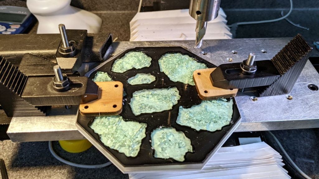
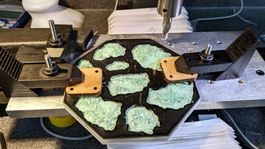
So I clamped it to the Sherline’s tooling plate and milled off the rim:
Smashed Glass Coaster – meniscus removal
Given the Sherline’s cramped work envelope, all the action took place along the rearmost edge, requiring eight reclampings indexed parallel to the table with a step clamp.
The cutter cleared off everything more than 0.3 mm above the surface of the glass chunks. I could probably have gone another 0.1 mm lower, but chopping the bit into the edge of a shattered glass fragment surely wouldn’t end well.
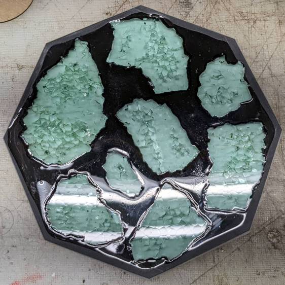
Polishing the dark gray milled surface might improve it slightly, at the risk of scuffing whatever poured epoxy stands slightly proud of the glass:
Smashed Glass Coaster – leveled edge
Perhaps if I define it to be a border, everybody will think it was intentional.
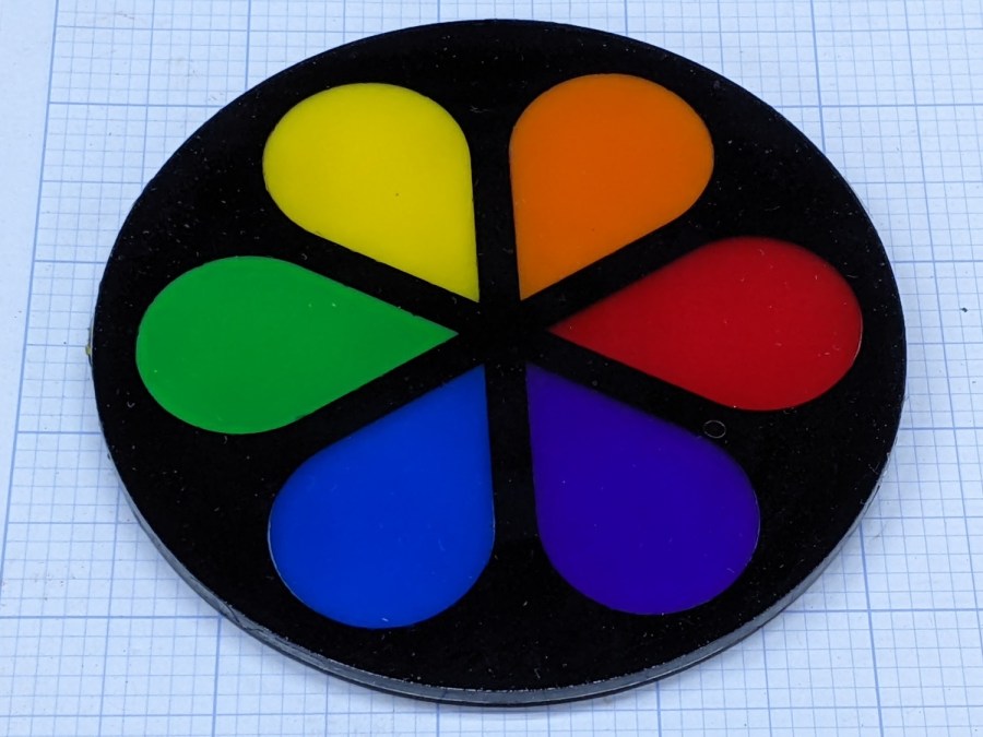
The petals stand slightly proud of the black top frame, as the colored sheets were marginally thicker than the black sheet, but it looks OK in person. They’re all epoxied to a transparent base plate, so the bottom view is pretty much the same:
Cut Acrylic Coaster – bottom
Because the bottom is perfectly smooth, I think it looks better than the top, which shows irregularities around the petals where the epoxy didn’t quite fill the gaps. There is one small bubble you won’t notice if I don’t tell you about it.
I laid a small bead of epoxy around the perimeter of the base, laid the black frame in place, ran a bead along the midline of each petal shape plus a drop in the round part, laid the petals in place, and hoped I didn’t use too much epoxy. It turned out all right, with only a few dribbles down the edge that wiped off easily enough.
I peeled the protective plastic off the top while the epoxy was still tacky, which pulled far too many fine filaments across the surface:
Cut Acrylic Coaster – frayed top
After the final cure, I managed to scrape most of them off with a thumbnail; I hope to never make that mistake again.
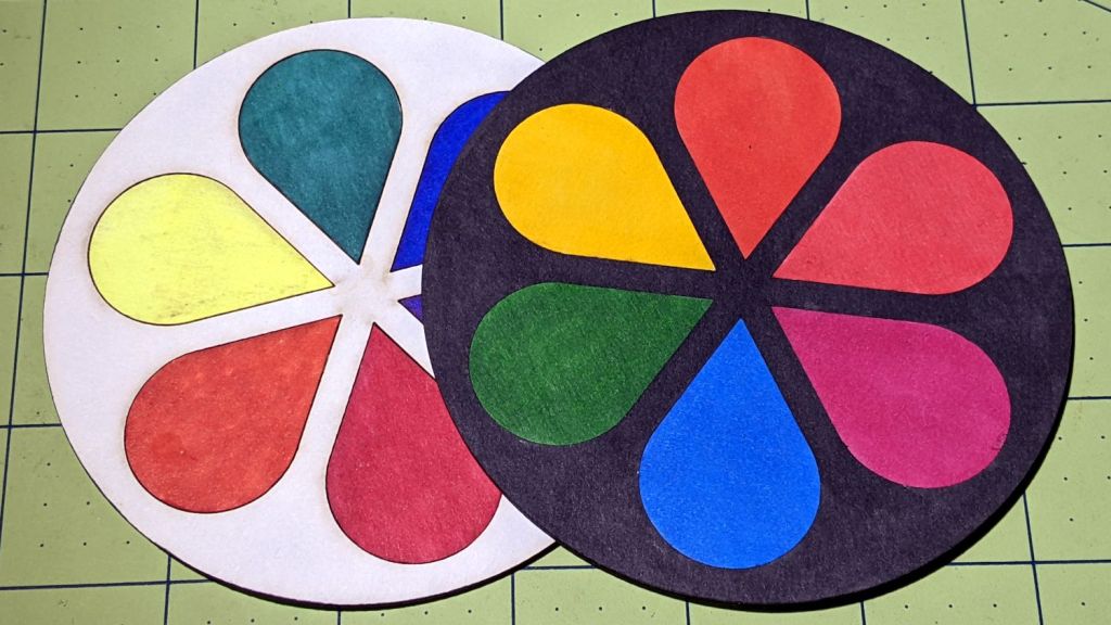
As you might expect, acrylic plastic’s pure saturated colors wipe the floor with Sharpie-scribbled white chipboard:
Chipboard coaster – rounded petals – front vs back cut
The black frame makes the whole thing overly dark, so the next attempt should use white or perhaps a transparent layer atop a mirror base.
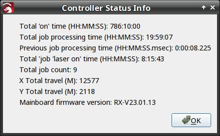
I think the Total job laser on time line says the power supply failed after firing the laser for a little over eight hours. The OMTech manual says the laser tube should last 1000 to 2000 hours (low vs high power), which suggests I should stock up on power supplies.
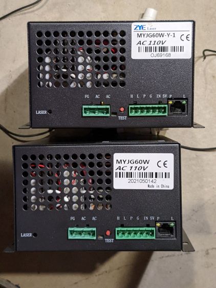
Its replacement just arrived:
OMTech replacement HV supply
It (bottom) seems to be a knockoff of the original ZYE Laser supply (top), with a similar model number and a “serial number” resembling a date from last year. All the connectors matched up, which isn’t too surprising.
The three most interesting inputs:
L = controller’s active-low L-ON enable output
IN = controller’s PWM output
P = jumper to G (circuit ground) — not water flow sensor
Also note the two AC power-line terminals directly adjacent to the TEST button, then consider insulation and stand-off distances before poking the button with your index finger.
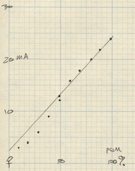
The power supply has a digital current meter, so I plotted output current against PWM input:
Laser Power Supply – mA vs PWM – overview
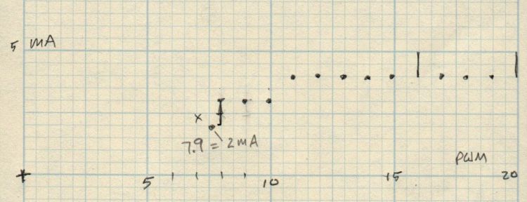
Taking more points at the low end, with vertical bars indicating single-digit flicker on the meter:
Laser Power Supply – mA vs PWM – 0 to 20 PWM
I have little reason to believe the meter reading indicates the true current with any accuracy and I know CO₂ laser output power does not scale linearly with the current.
But it’s cutting again, which is a step in the right direction.
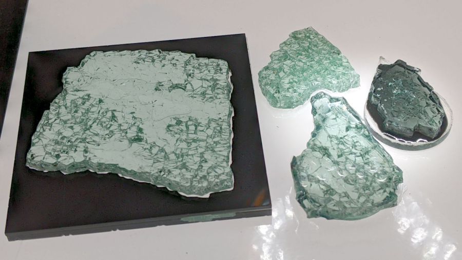
Just to see what happens, I laid some smashed glass in puddles of epoxy:
Smashed Glass vs epoxy – samples
Backlighting with the LED light pad reveals more detail:
Smashed Glass vs epoxy – backlit samples
The chunk on the left is the proof-of-concept shot glass coaster with a form-fit black acrylic mask atop a clear epoxy layer on a clear acrylic base. The chunk at the top is raw shattered glass fresh from the pile. The two chunks on teardrop acrylic scraps are bedded in transparent black and opaque black tinted epoxy.
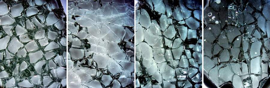
A look through the microscope at all four, laid out in that order, with the contrast blown out to emphasize the grain boundaries:
Smashed Glass vs epoxy – magnified comparison
You may want to open the image in a new tab for more detail.
The raw chunk has air between all its cuboids, so it’s nicely glittery. All the others have much of their air replaced by epoxy.
Clear epoxy produces an essentially transparent layer where it fills the gaps, because its refractive index comes close enough to the glass. The stretched contrast makes the gaps visible again, but the backlit image shows the unassisted eyeball view.
Transparent black dye sounds like an oxymoron, but it fills the gaps with enough contrast to remain visible. The overall chunk is not particularly glittery, but it’s OK.
Opaque black dye produces a much darker tint; the slightly tapered thin layer between the glass and acrylic (the small white circles are air bubbles) cuts down on the transmitted light. The gaps remain nearly as prominent as in the air-filled chunk, although with very little glitter.
Bedding the glass in epoxy against an acrylic sheet should reduce its tendency to fall apart at the slightest provocation, although the proof-of-concept poured coaster showed the epoxy must cover the entire edge of the glass sheet to bond all the slivers in place.
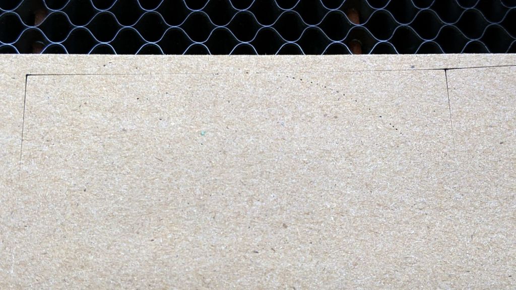
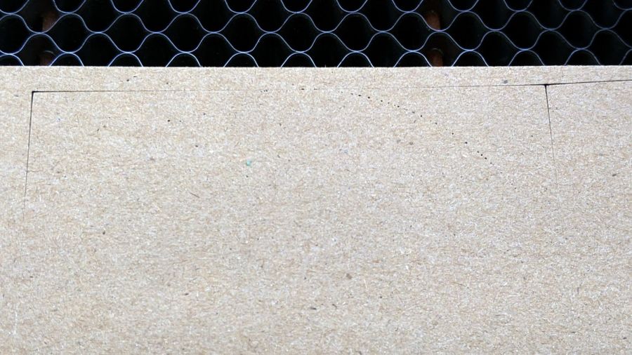
Setting up a piece of MDF and hitting the Frame button produced a lightly scorched line around the part perimeter, plus a slightly diagonal track leading from / to the Home position in the far right corner:
Fire while framing tracks
Doing another pass with LightBurn’s rubber-band frame produced the faint dotted circle.
Huh. Didn’t useda do that.
The laser should not fire while framing and, having just installed LightBurn’s 1.2.01 update, suspicion instantly fell on the most recently changed thing.
Which turned out not to be the case, as LightBurn’s tech support pointed out:
This is generally an indication of a failed high-voltage power supply, not a software issue.
OMTech’s support requested a video of the equipment bay, which didn’t seem like a useful way to convey the situation. Instead, I sent pix.
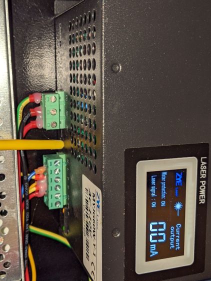
This picture shows the status of the 60 W laser power supply while the laser is incorrectly firing:
OMTech 60W Laser – uncommanded framing fire
The power supply has two LEDs on what looks like, but is not, an Ethernet jack near the bottom:
Orange P LED: good water flow
Green L LED: controller’s PWM signal
The LASER orange LED near the top turns on when the HV output is active and the laser should be firing.
In this case, L LED is off and the LCD shows “Laser signal OFF”, but the LASER LED is on and the LCD shows 2 mA beam current: the laser beam is ON, even though the controller has not activated the PWM signal.
Not only that, but I discovered the laser would fire while framing even with the lid up and the “safety interlock” sensor active.
Totally did not expect that.
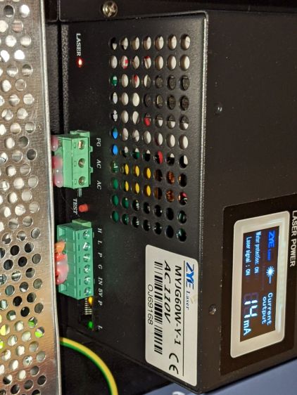
For comparison, the power supply status during a manual pulse at 49% power:
OMTech 60W Laser – manual pulse 49%
In that case, the L LED shows the PWM signal is active, the LASER LED is on, and the LCD shows 14 mA of current to the tube. That’s how it should work.
Although the function of the TEST button seems very lightly documented, pressing it did not turn on the output (the LASER LED is off), despite lighting the L LED:
OMTech 60W Laser – Test button pressed
OMTech confirmed my suspicion:
We are afraid that the laser power supply is defective
Making a coaster with petals from the NBC peacock turned out to be trickier than I expected:
Chipboard coaster – rounded petals
Protracted doodling showed that I cannot math hard enough to get a closed-form solution gluing a circular section onto the end of those diverging lines:
Chipboard coaster – rounded petal geometry doodle
However, I can write code to recognize a solution when it comes around on the guitar.
Point P3 at the center of the end cap circle will be one radius away from both P2 at the sash between the petals and P4 at the sash around the perimeter, because the circle will be tangent at those points. The solution starts by sticking an absurdly small circle around P3 out at P4, then expanding its radius and relocating its center until the circle just kisses the sash, thus revealing the location of P2:
The dist variable is the perpendicular distance from the sash line to P3, which will be different than the test radius r between P3 and P4 until it’s equal at the kissing point. The radius update is (pretty close to) the X-axis difference between the two, which is (pretty close to) how wrong the radius is.
As far as I can tell, this will eventually converge on the right answer:
Having found the center point of the end cap, all the other points fall out easily enough and generating the paths follows the same process as with the simple petals. The program performs no error checking and fails in amusing ways.
As before, laser cutting the chipboard deposits some soot along both sides of the kerf. It’s noticeable on brown chipboard and painfully obvious on white-surface chipboard, particularly where all those cuts converge toward the middle. I applied low-tack blue masking tape as a (wait for it) mask:
Chipboard coaster – tape shield
Whereupon I discovered the white surface has the consistency of tissue paper and removing the tape pretty much peels it right off:
Chipboard coaster – white surface vs tape
Putting the chipboard up on spikes and cutting it from the back side, with tabs holding the pieces in place (so they don’t fall out and get torched while cutting the next piece), should solve that problem.
In the meantime, a black frame conceals many issues:
Chipboard coaster – rounded petals – front vs back cut
I must up my coloring game; those fat-tip markers just ain’t getting it done.
This file contains hidden or bidirectional Unicode text that may be interpreted or compiled differently than what appears below. To review, open the file in an editor that reveals hidden Unicode characters.
Learn more about bidirectional Unicode characters
This file contains hidden or bidirectional Unicode text that may be interpreted or compiled differently than what appears below. To review, open the file in an editor that reveals hidden Unicode characters.
Learn more about bidirectional Unicode characters
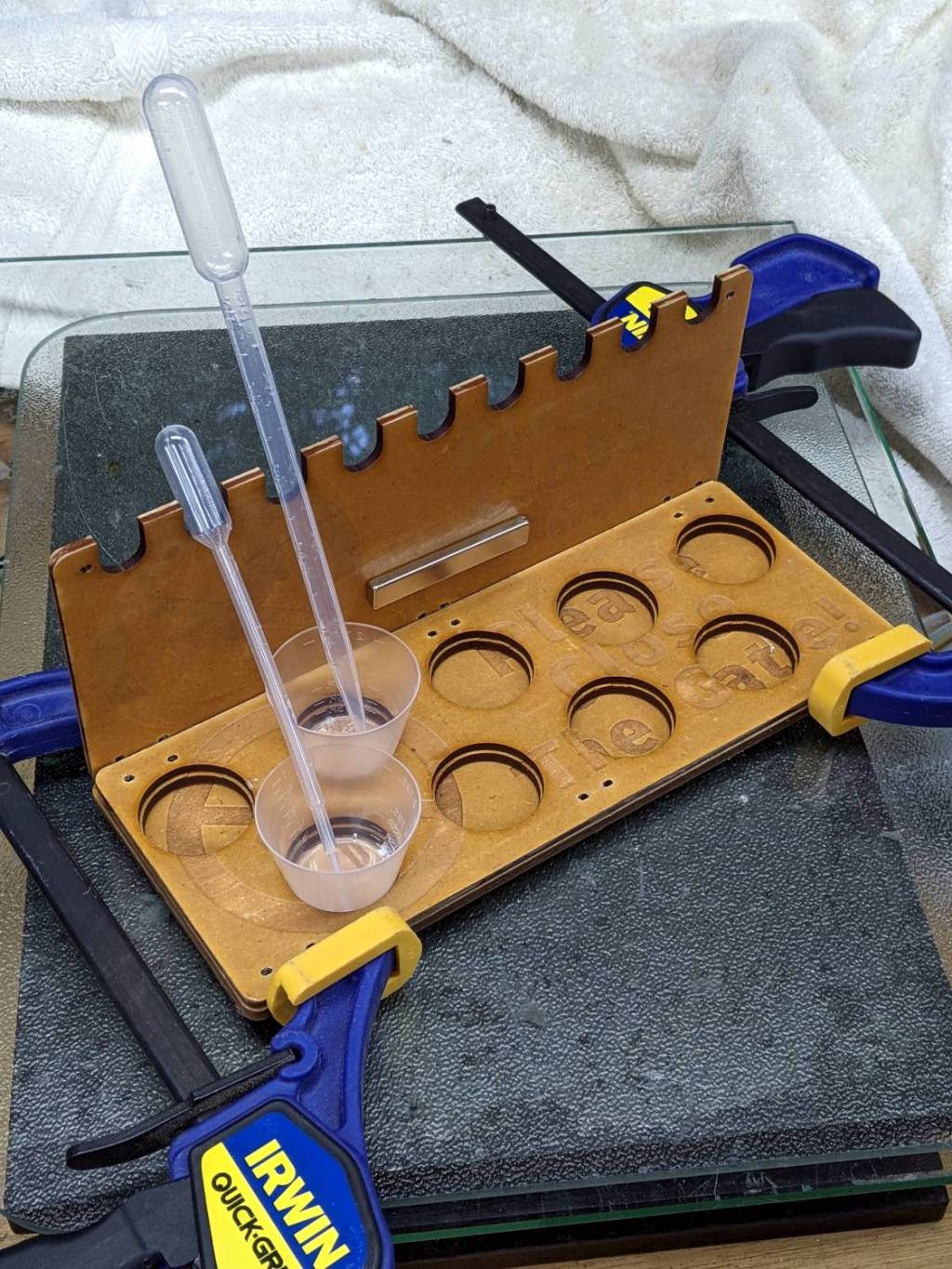
First you mix the epoxy, then you blend in the dye, then you dispense it into the thing you are making. If you’re using many colors, this is obviously not the right way to go about it:
The bar magnet holds the backplate against a bench block to keep it at right angles to the base while the adhesive cures. The base is three layers of MDF with no, small, and large holes fitting the cups. I expect many epoxy spills; scrap MDF reduces deep emotional bonding to the result.
The LightBurn project has the sign outline as a tool layer to simplify aligning the victims with the laser path, plus one layer defining the cuts for the three plates. I exported it as an SVG image with the same information as colored vectors for use in whatever laser control program you might use.


