Ed Nisley's Blog: Shop notes, electronics, firmware, machinery, 3D printing, laser cuttery, and curiosities. Contents: 100% human thinking, 0% AI slop.
A screws in one of Mary’s eyeglasses unscrewed itself, but, miraculously, we found it and I retired to the shop.
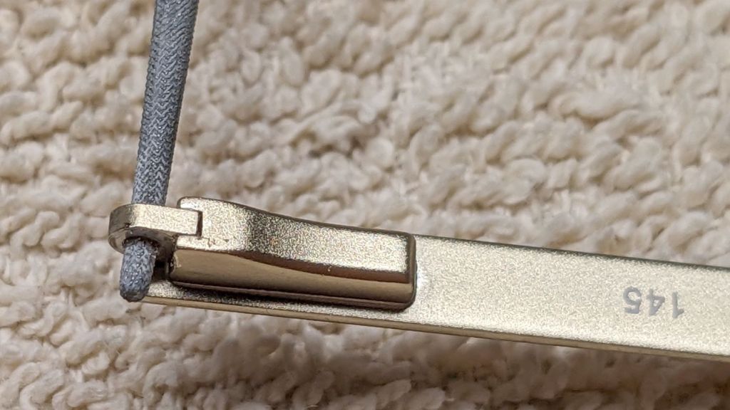
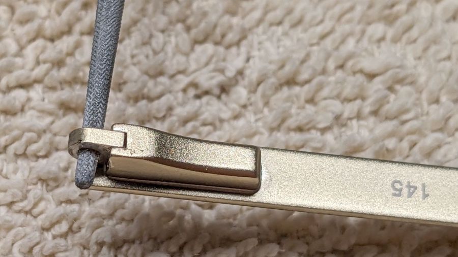
Because the glasses have spring temples, the screw would not align no matter what force I applied to it:
Eyeglass spring temple – screw misalignment
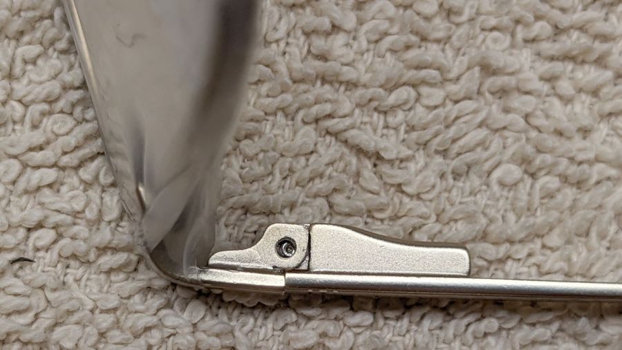
So I just embiggened the hole until the available force did the trick:
Eyeglass spring temple – hole filing
Dots of Loctite worked into the threads should prevent that from happening again, but I’ve learned to never say never.
In retrospect, the temple pivots have an exposed slot that I think would allow jamming a block in place after pulling the spring-loaded pivot outward. Temple springs are impossibly stiff and I have previously failed to budge them in glasses without the slots, so I don’t know how well that might work.
Verily: If brute force isn’t working for you, then you’re not using enough of it.
During the course of diagnosing and fixing the latest oven igniter failure, an unrelated series of events produced a flood under the kitchen sink and across the floor. After cleaning up the mess and determining the floor under the cabinet was merely damp, rather than wet, I drilled a hole suitable for another PC cooling fan from the Box o’ MostlyFans, installed the fan to pull air upward, and let it run for a couple of days while watching the humidity drop.
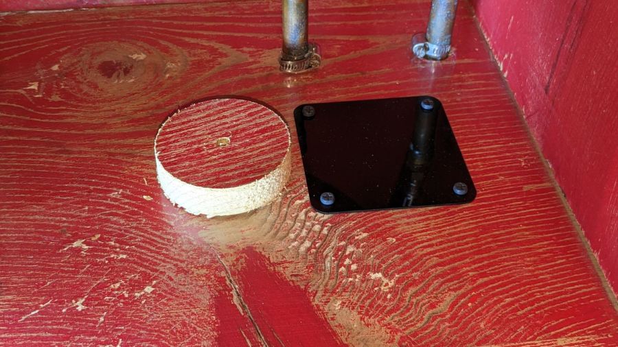
Fortunately, I had a hole saw exactly the right size for an 80 mm case fan:
Kitchen sink – fan cover plate
I will lay big money on a bet saying your kitchen cabinets don’t have Real Wood like that, nor are the interiors painted bold Chinese Red. This place really is a time capsule from 1955.
While the drying happened, I made a hole cover from 1.5 mm black acrylic and, there being no style points involved, rounded up a quartet of black-oxide self-drilling sheet metal screws to hold it in place.
Although it’s not obvious, there’s a layer of transparent plastic “shelf paper” in there. It covers the fan hole under the cover, so any future spills will have approximately the same difficulty reaching the floor as this one did.
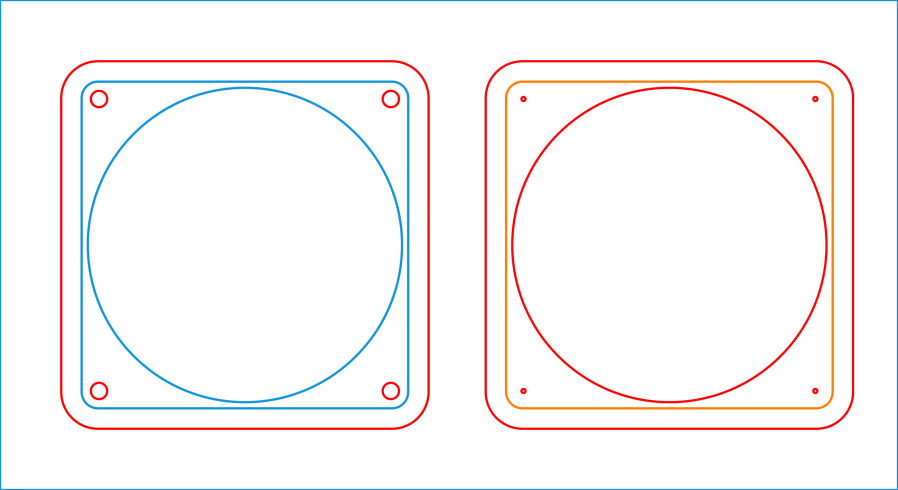
The LightBurn layout produces both the fan cover and a template to mark the four screw holes around the fan opening:
Kitchen Sink Fan – LB layout
The blue tool layer lines serve as a guide for the rest of the cover layout; the matching orange square on the right marks the fan outline on the drill template as a quick size check.
No need for an SVG version, because now that you have the general idea, it’s easy to recreate it for your own fan.
Apparently igniters last about eight years, regardless of provenance, because the igniter just failed, with the usual symptoms of low current draw (about 2 A), failed ignition, and a faint smell of propane (well, mercaptan) before the safety valve kicked in:
Oven igniter – location
The new igniter, another low-buck Amazon offering, came with half a green plastic connector block that mated neatly with the existing half under the oven. Unfortunately, the new wires had female pins crimped on their ends, rather than the male pins required by the existing connector and the ceramic wire nuts I’d used to join the previous igniter to the OEM connector were non-removable.
So I trimmed the old wires to a usable length and applied the new ceramic wire nuts to the stubs:
Oven igniter – connector rewiring
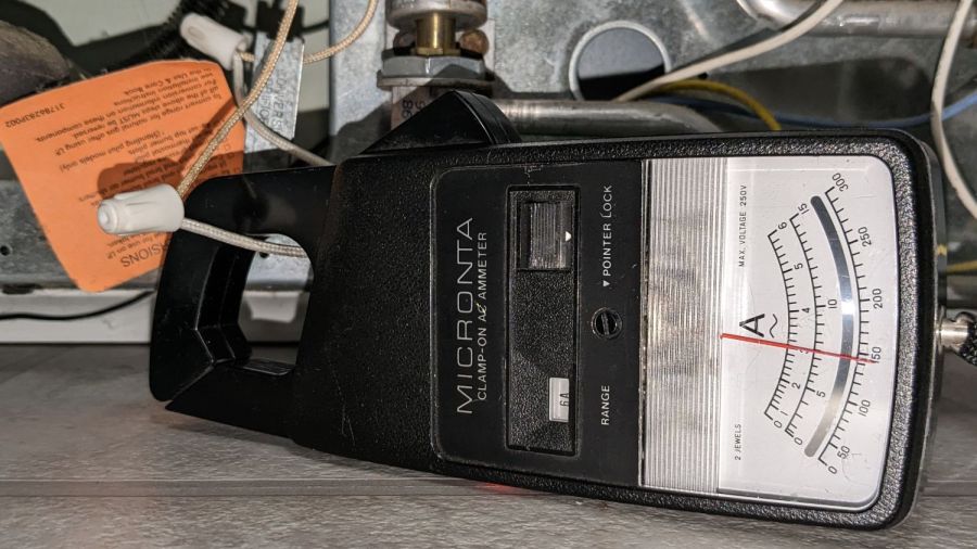
Also as before, the new igniter measures 3 A, definitely below the low end of the valve’s 3.3 to 3.6 A range:
Oven igniter – current test
If this one lasts eight years, I won’t be the guy replacing it …
Another LightBurn forum discussion helped me work through how the Z Axis motions should work. This is a lightly edited mashup of several of my comments and builds off a discussion concerning the proper setup of the axis homing / direction settings; the starting point concerns whether the “up” jog arrow should make the platform go up or down.
It may be a matter of definitions and the consistency thereof.
An earlier comment in the thread said “The Machine’s Z-Axis operates in the wrong direction!”, so I had (erroneously) suggested flipping the Direction Polarity control to reverse it, which made it move in the other (wrong) direction when homing.
Knowing that, I suggested restoring Direction Polarity for the correct homing direction, then flipping Invert Keypad Direction reverse both the keypad and LightBurn directions.
If that does not sort the directions out the way you want, then it’s not clear how to proceed.
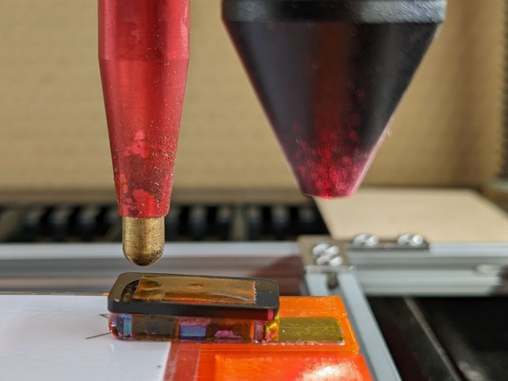
The Focus Distance parameter determines how far the U (or Z) axis moves from its default position after the focus pen / switch trips: it adds distance and can only be positive. Mine arrived at 0.0 mm and remains that way.
That default position comes from the U (or Z) axis parameter Home Offset controlling the backoff distance from the switch trip point. Mine is at 10.1 mm, which positions the nozzle 18.5 mm from the material and puts the focal point at the surface.
I think the intent is to have the vendor determine Home Offset to make the focus switch work correctly with a minimum mechanical backoff, then add Focus Distance to match the actual lens focal distance. The settings on my machine came from OMTech, but I don’t regard them as unalterably correct.
For my Sherline CNC mill, jogging “up” increases the distance between the tool and the table by raising the spindle.
For my MakerGear M2 3D printer, jogging “up” increases the distance between the nozzle and the platform by lowering the platform.
In both cases, the “up” button corresponds to an increasing distance.
I think the idea behind the Ruida’s setup parameters is to put the just-homed Z axis origin at the platform surface, with the jog buttons (and LightBurn’s motions) then raising the focus point to the surface of the material by lowering the platform: positive numbers increase the distance.
With that in mind, picking the Invert keypad direction setting so that the up button makes the platform go down is correct: it increases the distance from the initial home position. That should also make positive Z steps increase the distance (away from the work) and negative steps decrease it (into the work), which seems sensible.
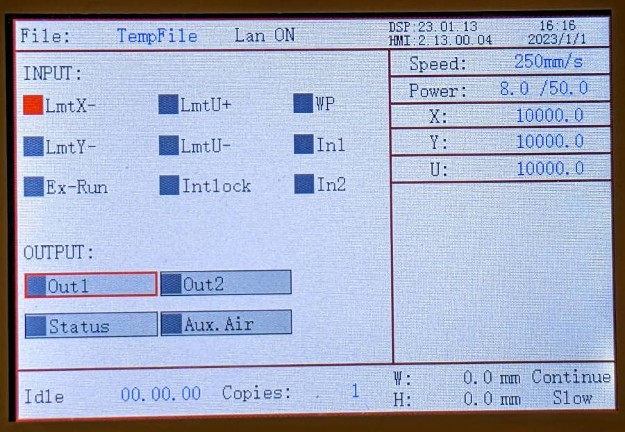
A discussion on the LightBurn forum prompted an investigation of how Ruida laser cutter controllers handle their homing operation. This is a lightly edited version of (some of) my comments with added pix.
There being nothing quite like a good new problem to take one’s mind off all one’s older problems, I just did some tinkering with the X axis settings…
This is on a Ruida-ish KT332N, but the manual’s verbiage is pretty much the same as the 6445G.
Changing the settings requires a controller reset, which will trigger a homing operation if it’s enabled.
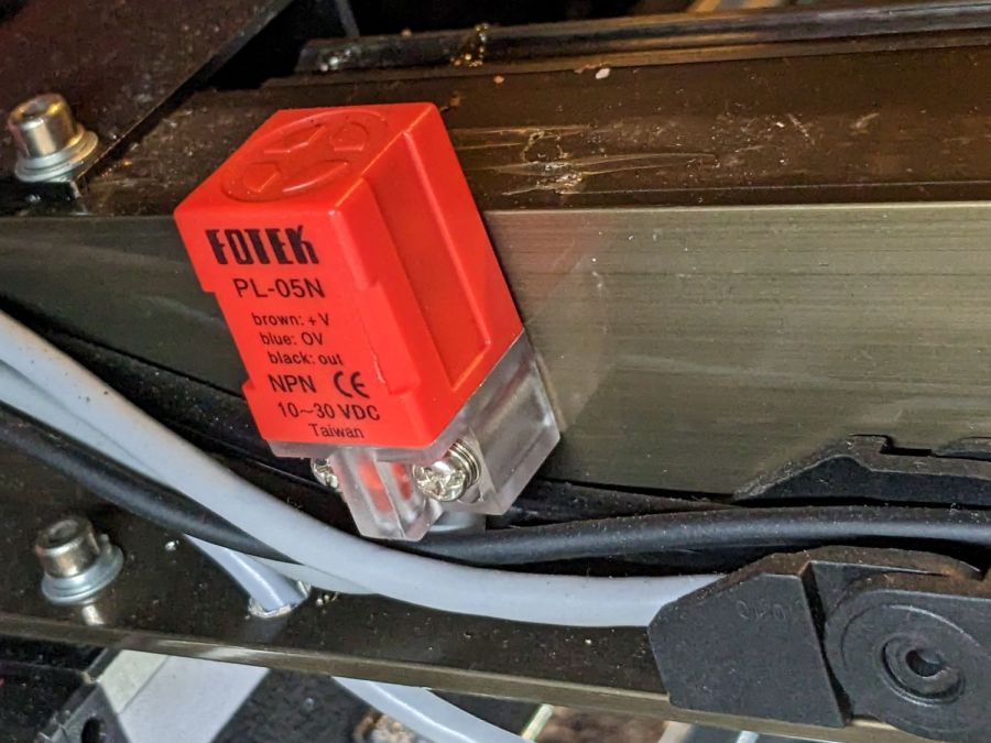
Limiter Polarity inverts the sense of the limit switch input signal. My OMTech has Normally Open proximity sensor switches:
OMTech Fotek PL-05N proximity limit switch
So the default setting of False makes it inactive in the middle of the platform.
I set it to True, which made it active in the middle of the platform:
Ruida KT332N Controller – inverted X limit switch
So True would be the correct setting for a Normally Closed switch.
Direction polarity sets the direction the axis moves during reset, which must be toward the home switch. Mine was set to False and it homes toward the right side where the limit switch sits.
I set it to True and it started homing toward the left, where the limit switch isn’t. Hitting Esc on the control panel stopped the homing process and left the head in the middle of its travel, unhomed.
Apparently Direction Polarity directly controls the DIR signal to the stepper motors, because both the control panel keys and LightBurn’s motion buttons then moved “the wrong way”.
That does not affect LB’s machine coordinate origin, which remains at the top right of the layout, or the orientation of the X axis, with values increasing toward the left as usual.
Invert keypad direction inverts the motion direction with respect to the homing motion. Mine was False, but flipping it to True reverses both the keypad and LB directions.
I think Limit Trigger refers to “hard limits”, which requires a limit switch at each end of the axis, but my controller does not have the + inputs that would allow me to test that. The controller doc says it uses “soft limits” to prevent out-of-bounds motion by using the home position and maximum axis travel value.
So the available options allow all possible combinations of:
NC or NO limit / home switches
Homing direction
Keypad / LB motion commands
A reasonable sequence seems to be:
Set the switch polarity to match the hardware
Set the homing direction toward the switch
Set the “keypad” direction to match your expectations
With that in mind, careful experimentation on the actual controller in hand seems prudent …
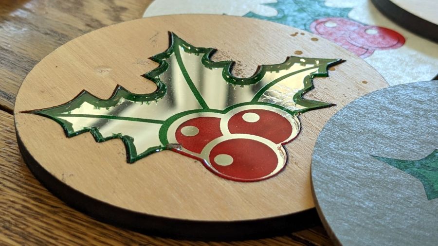
The improved Holly Mirror Coaster looks pretty good:
Holly Coaster – overview
Until you realize some of those specks aren’t surface dust and take a closer look:
Holly Coaster – mirror speckles 1
The surface scratches are doubled by their reflection in the bottom mirror. The little dots that aren’t doubled reveal marks in the mirror surface itself.
In this case, they cause defects in the mirror coating allowing alcohol from the fat-tip permanent markers coloring the engraved areas to hit the acrylic. The starbursts come from stress cracks around the punctures.
Peering even closer shows similar cracks along the edges of the colored areas:
Holly Coaster – mirror speckles tight detail
Not much to do about the random speckles, but it’s obvious I must up my coloring game.
Which would be significantly easier if rattlecan spray paint sprayed at winter temperatures …
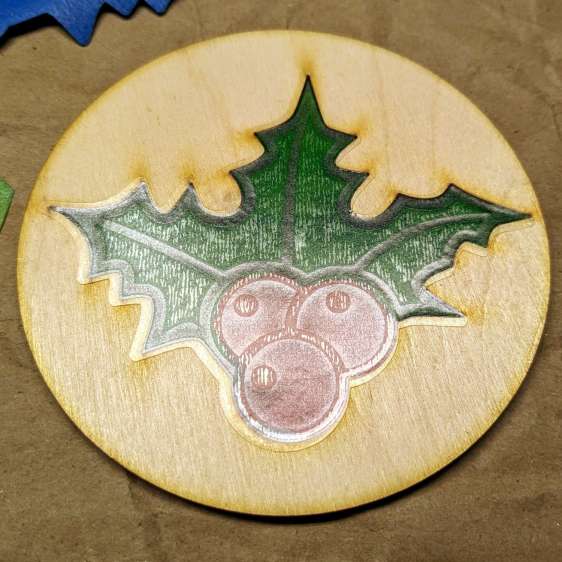
Other than demonstrating that it’s possible to laser-engrave a 3 mm deep pocket in a ¼ inch thick piece of scrap paneling, the process didn’t have much to recommend it:
Holly Coaster – mirror flaws
So I re-did the layout to put the 3 mm mirror in 3 mm thick plywood:
Holly Coaster – overview
The coaster has a self-adhesive cork pad on the bottom, which required an intermediate adhesive layer holding the aluminized Mylar reflector on the bottom of the mirror to brighten the colored areas.
The LightBurn layout shows all the pieces:
Holly Mirror Coaster – LB layout
The plywood cuts with the good side down, although “good” is certainly a judgement call with B/BB grade plywood. I cover the good side with blue painter’s tape to reduce scorch marks. In a real application, you’d do some sanding and finishing, probably before cutting; in this case, I want to see what happens to bare wood in coaster duty.
Engrave and cut the mirror with the backing upward:
I colored the engraved areas with fat-tip permanent markers, despite knowing the alcohol will crack the acrylic. In real life, you’d use spray paint, probably with laser-cut tape masks.
The adhesive layer extends 2 mm beyond the mirror perimeter to stick onto the bottom face of the plywood:
Holly Coaster – adhesive placement
Peeling off the paper reveals the adhesive tape stuck to the back side of the mirror:
Holly Coaster – adhesive exposed
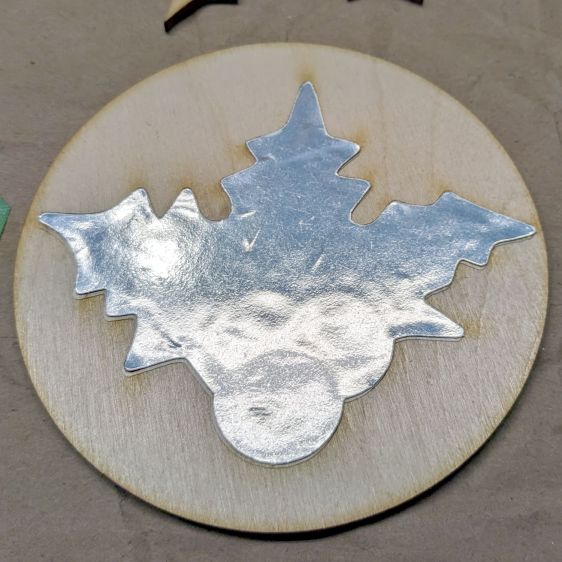
Apply the similarly embiggened aluminized Mylar to the adhesive:
Holly Coaster – mylar placed
Cutting the holly shape directly from the original foot-square adhesive sheet lets me tuck smaller shapes into the remaining uncut areas. In a production environment, however, joining the Mylar and adhesive (perhaps using pre-cut squares), then cutting them as one sheet would definitely simplify the process.
Then peel-n-stick a cork disk (thus explaining why the plywood is exactly 4 inch OD) on the bottom:
Holly Coaster – edge view
I’ve been aligning the cork by feel, which explains the half-millimeter overhang along the right side. Inexplicably, I have yet to justify an alignment fixture.


