Ed Nisley's Blog: Shop notes, electronics, firmware, machinery, 3D printing, laser cuttery, and curiosities. Contents: 100% human thinking, 0% AI slop.
Because the lamp has a big nut apparently holding the pole socket to the base, I figured a dab of threadlock on the pole or the base would solve the problem: lock the pole to the socket, then remove the nut to disassemble when needed. That turned out to be a Bad Idea™.
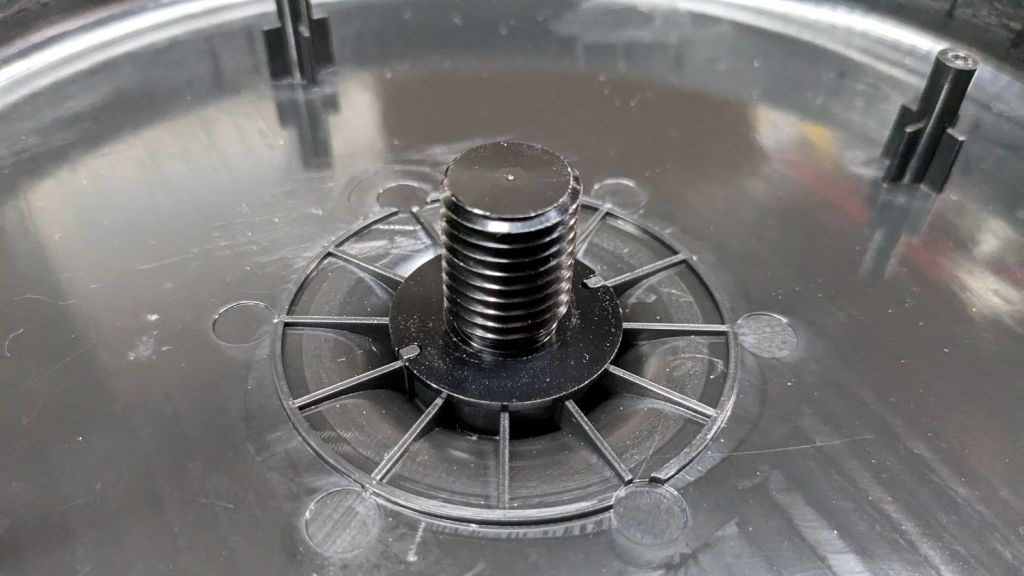
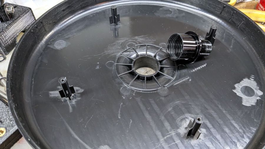
The socket is a plastic part separate from the base cover plate:
Miroco floor lamp base – socket
A pair of keys prevent the socket from rotating in the hole:
Miroco floor lamp base – socket in place
Four threaded bosses (two visible there) hold the rim of the cover to the weight, with the socket doing the hard work.
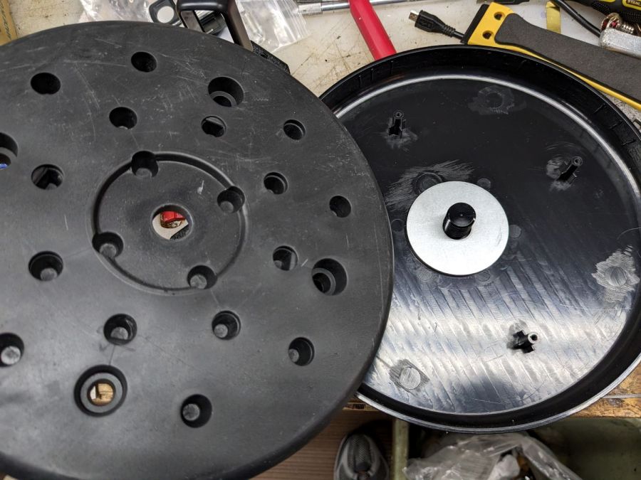
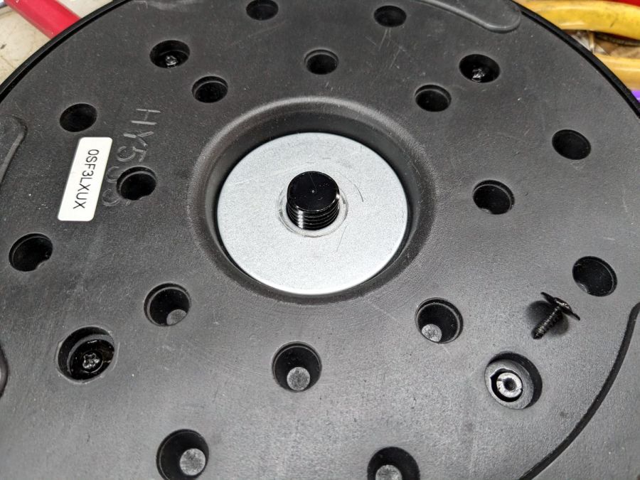
A fender washer atop the weight distributes stress from the pole:
Miroco floor lamp base – weight top washer
Another fender washer on the bottom of the weight lets the nut jam against steel, rather than soft plastic:
Miroco floor lamp base – weight bottom washer
FWIW, the nut is either a perfect 15/16 inch or, more likely, a sloppy 24 mm.
In any event, permanently locking the pole to that socket will also lock the pole to the base, with no way to dismantle the lamp when I must once again repair it.
Perhaps a wrap of PTFE tape on the threads will stiffen it enough?
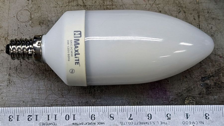
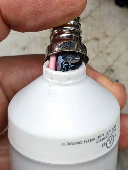
The bathroom ceiling fixture has a nightlight position that we use occasionally, but eventually the little 7 W Christmas Tree bulb failed and I installed this hulk from a box of CFL bulbs a friend scrapped out after switching to LED bulbs:
MaxLite CFL – overview
I never tested whether it actually drew 3 W, but, hey I could feel good. Right? Right?
Anyhow, this one failed after a few years, too. The “bulb” envelope looked like it might make an attractive blinkie or glowie, so I decided to harvest it.
The candelabra screw base felt loose and popped off with a push:
MaxLite CFL – overflow cap
Perhaps they chose the envelope before finalizing the circuitry?
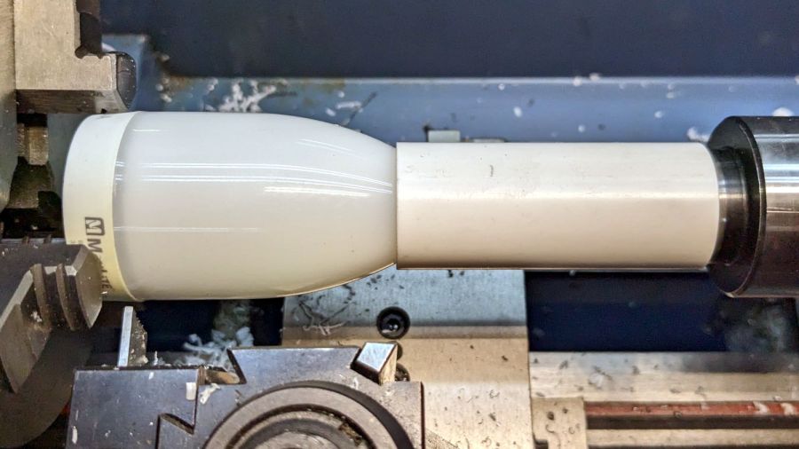
This is why you need a lathe in your shop:
MaxLite CFL – lathe cutting
It wasn’t particularly well centered, so that was done dead slow and finished with a few hand turns of the chuck. Obviously, I need a crank for the spindle.
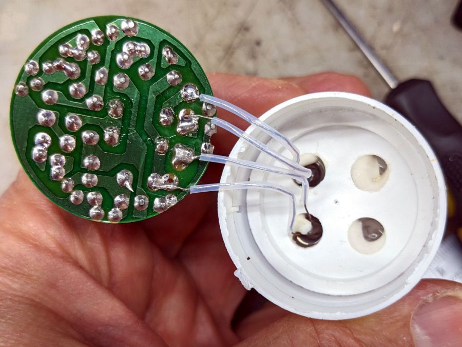
The rest of the circuitry is pretty well packed under that tall cap:
MaxLite CFL – circuitry
Pulling the PCB out revealed the tube wiring:
MaxLite CFL – tube wires
Cut the wires and chuck it up again:
MaxLite CFL – envelope turning setup
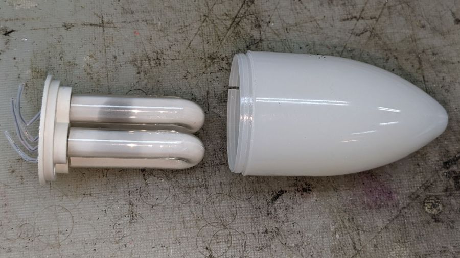
Turn dead slow again until it breaks through:
MaxLite CFL – envelope breakthrough
Then finish by hand:
MaxLite CFL – tube and envelope
It’s too cute to throw out, but … sheesh you can see why recycling this stuff is so difficult.
For whatever it’s worth, I replaced it with a 3 W LED candelabra bulb that is way too bright.
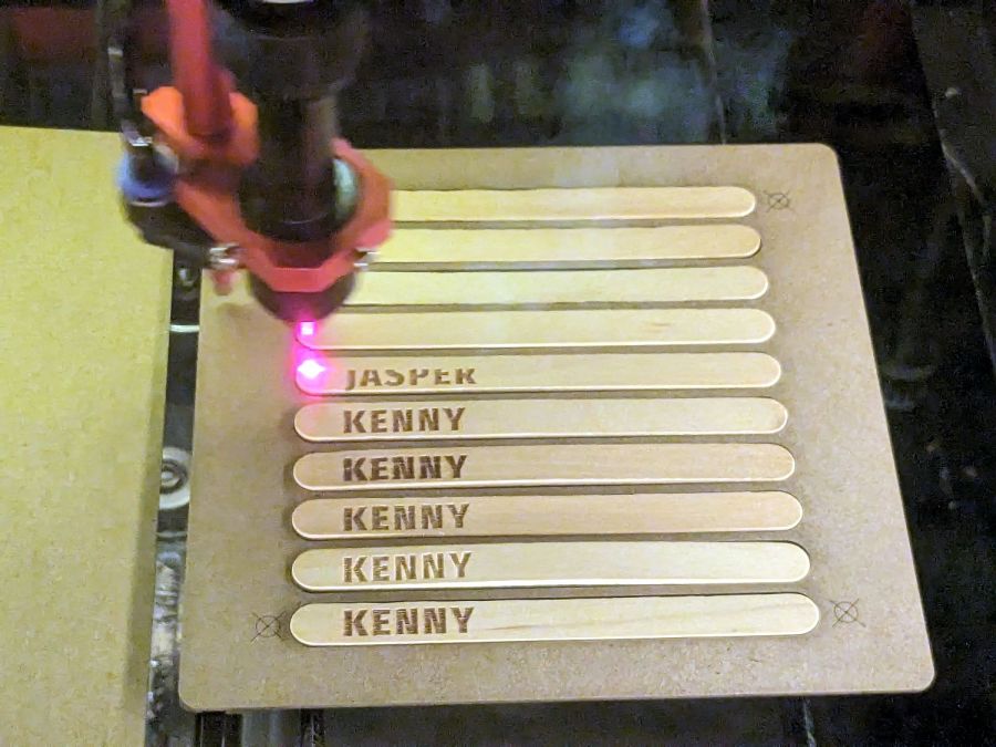
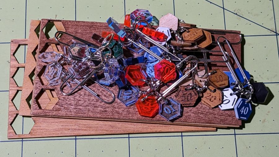
Our Young Engineer knits during rare moments of downtime and sketched an idea for stitch counters to mark progress between those moments. There being nothing like a new project to take one’s mind off all of one’s previous projects:
Stitch Counters – overview
These are more along the lines of feasibility / material tests than finished products, so you’ll see plenty of rough edges.
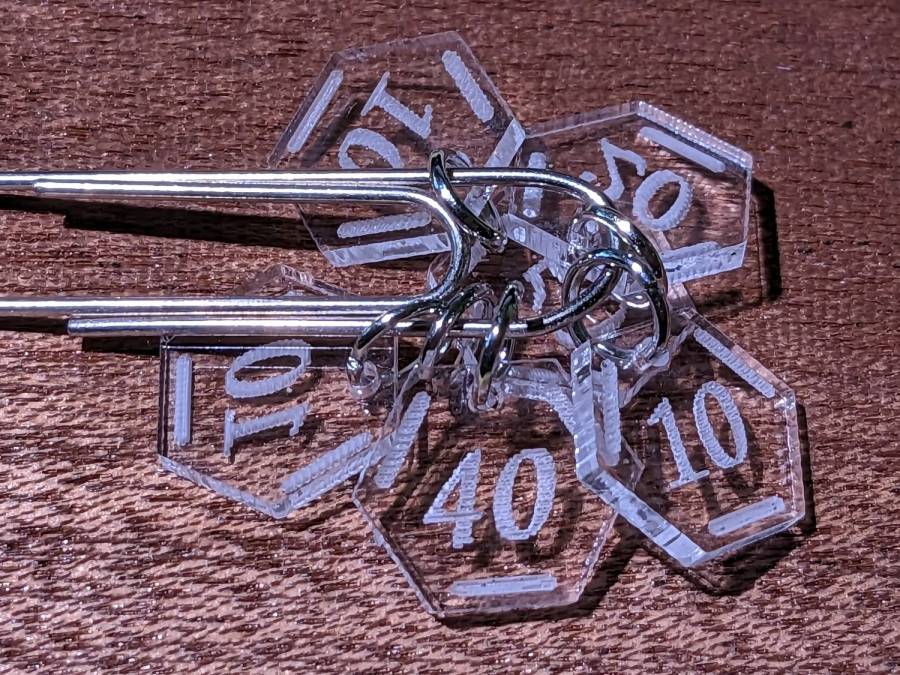
Prior to doing this, we agreed that 3 mm material was probably too thick, particularly given the small scale: the hexagons are 10 mm edge-to-edge with a 1.5 mm hole for the jump ring.
The jump rings are (mostly) 8 mm OD, which may or may not be the right diameter for all possible knitting needles.
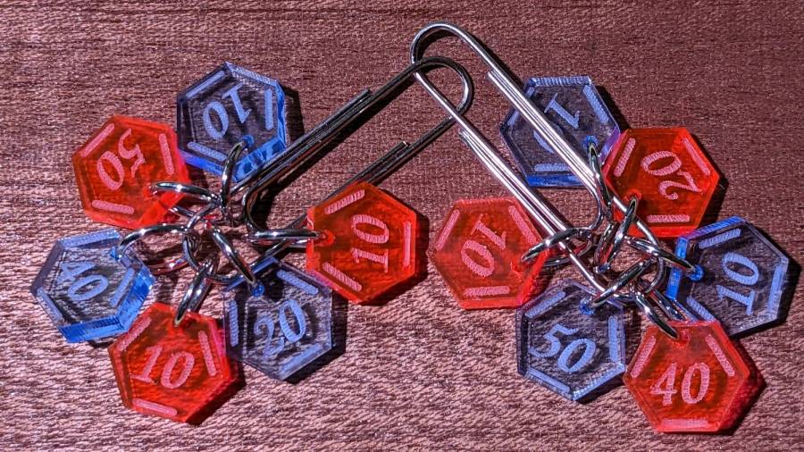
The count sequence goes 10 20 10 40 50 10 with alternating colors:
Stitch Counters – red and blue
Those came from 3 mm red and blue transparent acrylic, looking entirely too much like candy. Cutting two identical layouts from two different materials, then swapping a few counters, gives me two related-but-different sets. This idea is also subject to revision.
I like the set of 3 mm acrylic mirror counters colored with Sharpie:
Stitch Counters – mirror
Alas, the unprotected mirror backing won’t survive long in the real world and Sharpie ink tends to stress-crack the acrylic. Bonding a thin colored sheet / gel filter to the back with an adhesive sheet in between would work, although I don’t look forward to the fiddly alignment. Bonus: sticky edges are a nonstarter in this application.
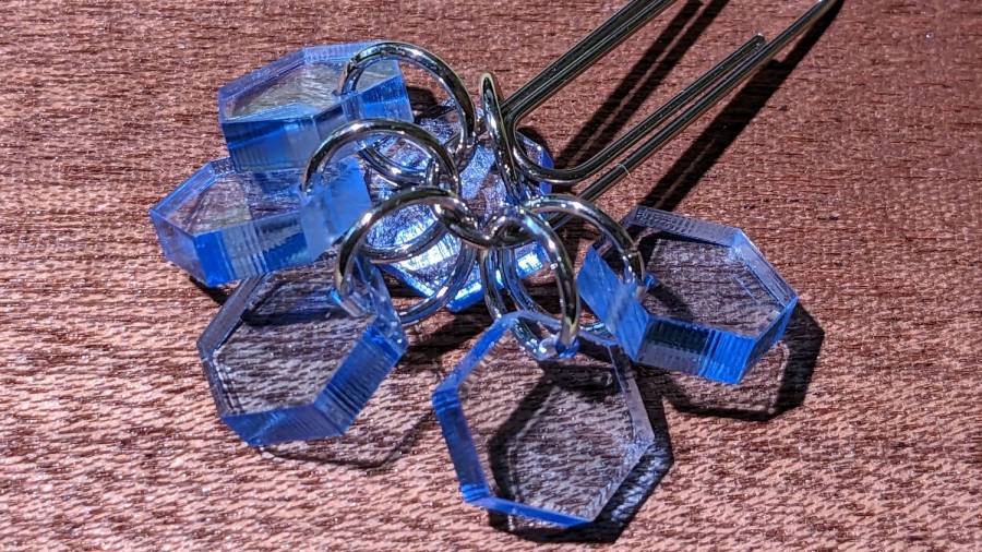
A setup error produced a set of unmarked counters that might still come in handy for something:
PXL_20230507_150124595 – Stitch Counters – blue blank
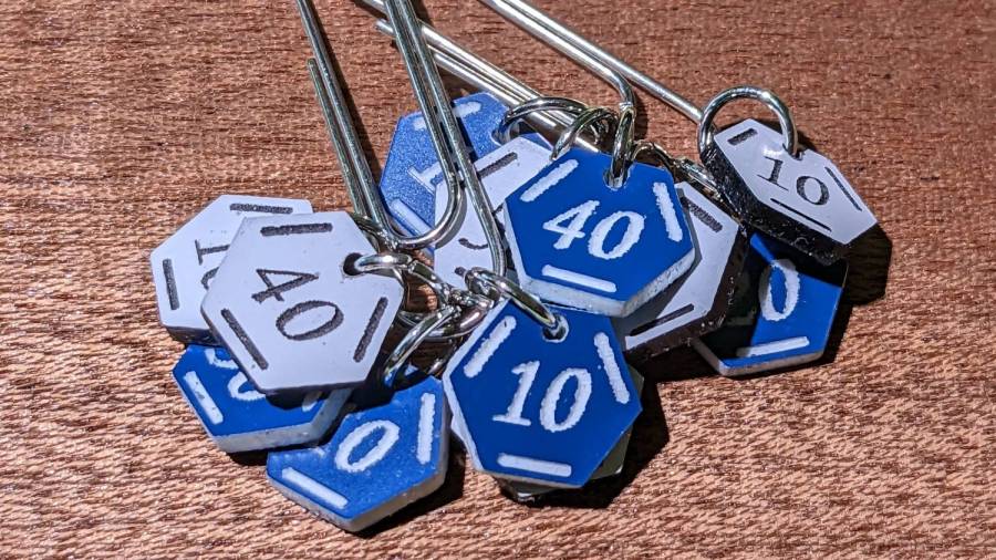
Trolase acrylic 1/16 inch = 1.5 mm sheets produce the most visible legends, in a relentlessly industrial sort of way:
Stitch Counters – Trolase
Those have a single thin layer atop a white or black base sheet, but three-layer 1.5 mm Trolase sheets with matching top and bottom colors (cladding on a white core) would look better.
If you can’t decide on a color, go clear:
Stitch Counters – clear
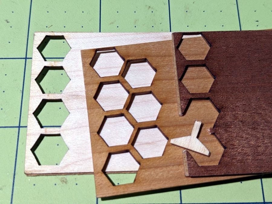
All of those appear on a background of some thin DIY plywood:
Stitch Counters – veneer plywood sheets
The bottom sheet is very pale veneer that came with a layer of genuine 3M 468 transfer tape with 200MP adhesive. I stuck three different veneers on three 100×50 mm rectangles of the stuff to make 1.5 mm thick “plywood”. The adhesive sheet provides lateral strength, not the wood fibers, so it’s not quite as easy to tear as the broken fragment would suggest.
The results look passable, although there’s room for improvement:
Stitch Counters – veneer plywood
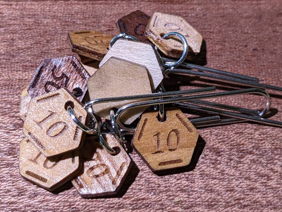
After engraving & cutting, I slathered them with clear polyurethane finish and hung them up to dry:
Stitch Counters – wood finish curing
I like the effect, but using the pale veneer for the bottom layer made them look identical from that side. Worse, two of the three top layer veneers had nearly identical colors (one has more grain) after the finish cured.
More thought seems in order, but at least I’ve explored some of the solution space.
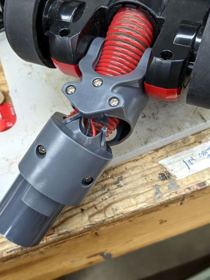
The knuckle joint on the Dirt Devil stick vacuum failed, so it followed us home instead of leaping into the trash:
Dirt Devil – broken swivel joint
Although the fitting seems to be made of ABS, it’s now missing major chunks of plastic in the high-stress areas, so rebuilding it seems not worth the effort.
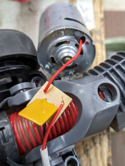
Because we don’t have any carpets and this one will never leave the basement, I extracted the carpet beater brush and its motor, only to find Yet Another Example of poor assembly practices:
Dirt Devil – stray strands
It’s a 12 V (-ish, I didn’t measure whatever comes out of the vacuum head) DC motor and those errant strands aren’t quite long enough to meet in the middle. The yellow rectangle is a thermal fuse that would be shorted out if the strands were a bit longer.
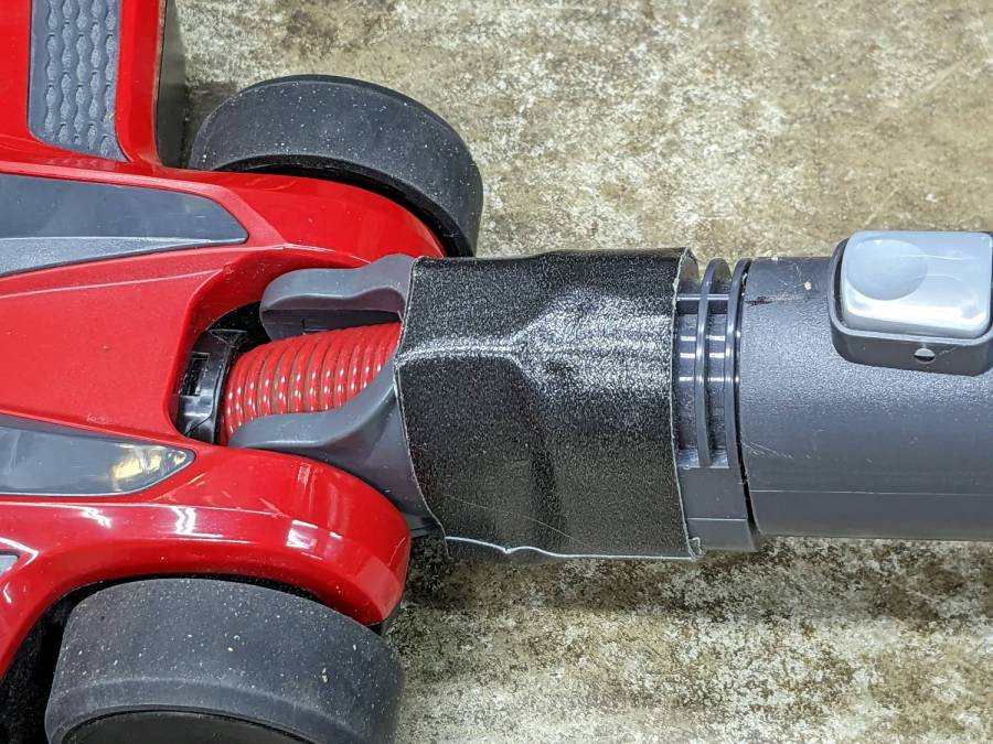
The broken joint lets the head swivel from side to side, but the elevation joint is still good. If I don’t expect too much, the thing might still suffice for extracting dust from under the benches:
Dirt Devil – taped joint
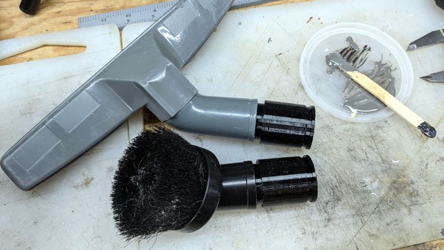
Worst case, I can swap in a classic floor brush using one of the adapters I made a while ago:
Dirt Devil adapters – assembled
That was easy, if only because I skipped the hard part …
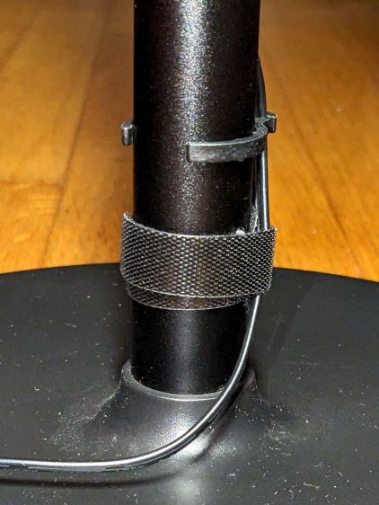
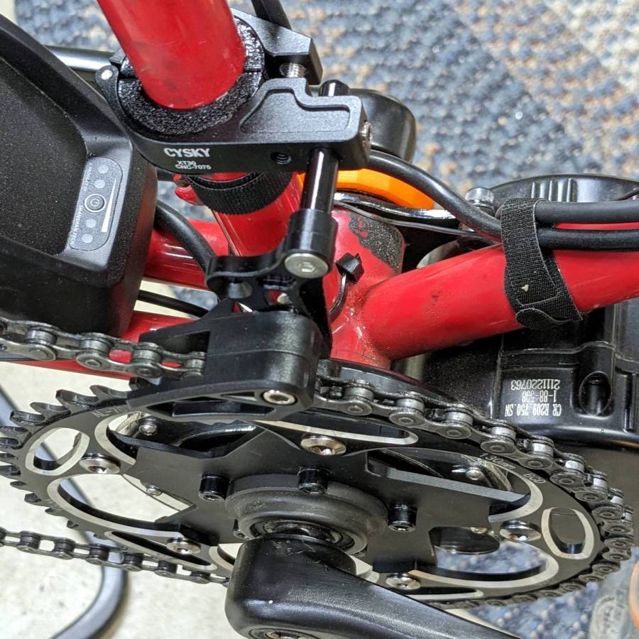
It’s more properly called a “chain guide” and is basically a shifter cage minus the mechanism:
Chain Catcher – side view
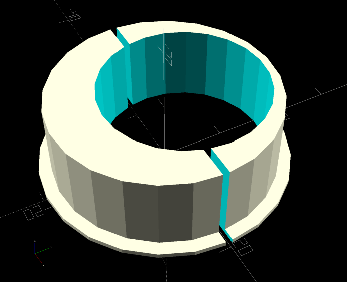
Because the Tour Easy frame has a 25 mm tube where the guide’s clamp expects a minimum 31.8 mm tube, a 3D printed adapter fills the gap:
Chain Catcher adapter ring – solid model
The hole is off-center because it seemed like a good idea, although it’s not strictly necessary. The flange helps align the pieces while tightening the clamp screw.
The guide cage clears the chain on all sides while up on the work stand, but there’s nothing like getting out on the road to find out why something doesn’t work as you expect.
This file contains hidden or bidirectional Unicode text that may be interpreted or compiled differently than what appears below. To review, open the file in an editor that reveals hidden Unicode characters.
Learn more about bidirectional Unicode characters
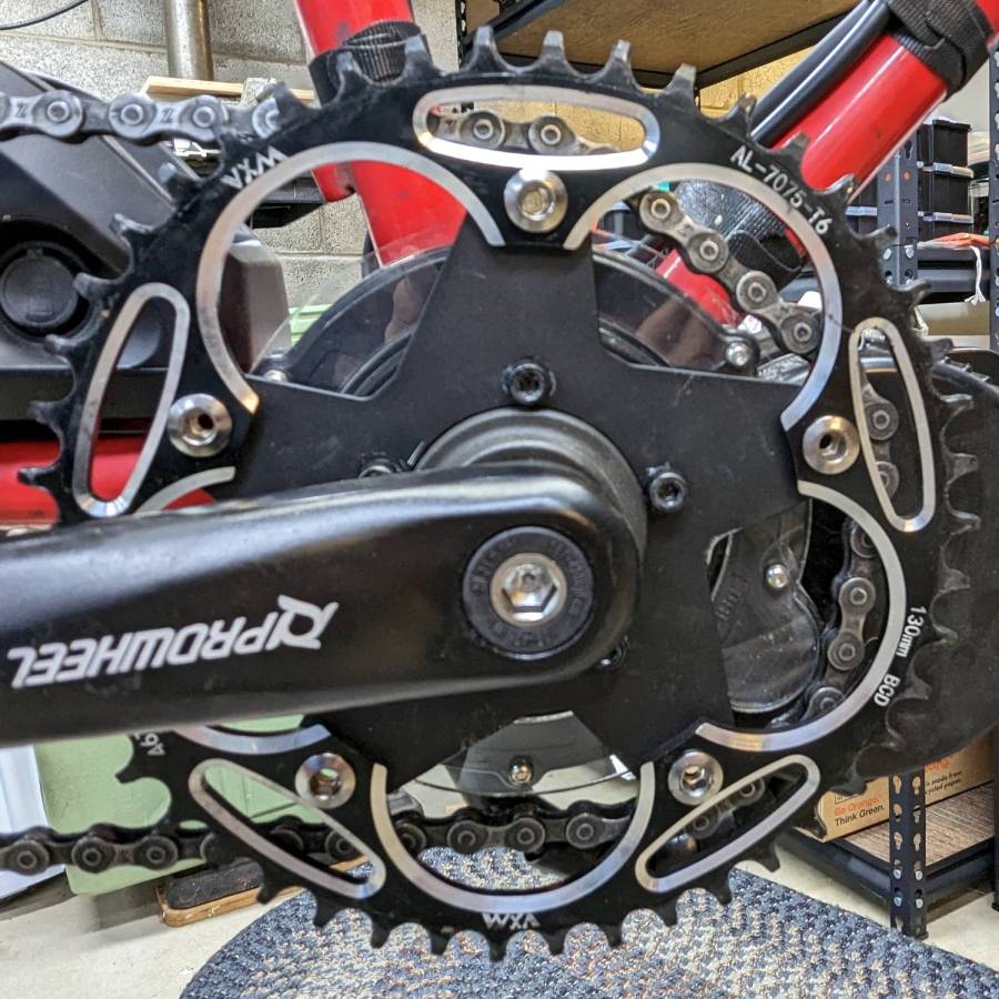
When the chain falls off the top of the chainring toward the motor, the part remaining engaged with the chainring will inevitably drag the rest into the gap between the motor and the chainring spider, whereupon it will jam firmly in place and be almost impossible to extract. Preventing this means filling the gap, which required several iterations:
Bafang motor gap filler – prototypes
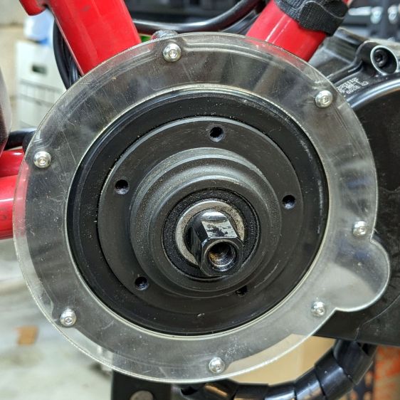
The Bafang motor has a cover held in place by seven M3 flat-head screws, shown here below a test filler using pan head screws:
Bafang motor gap filler – installed
Contrary to what you might think, the five screws that obviously sit on five points of a hexagon do not in fact sit 60° apart. How you find this out is by making the obvious layout, including the two screws bracketing the pinion gear in the lower right, then applying windage:
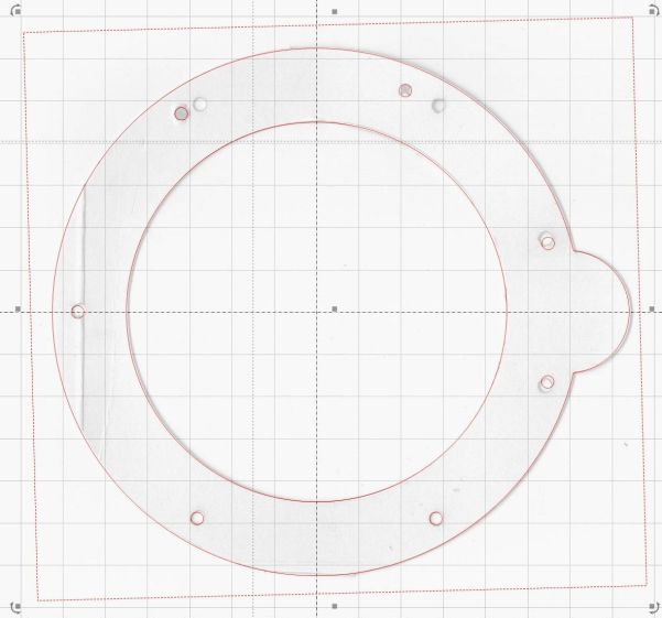
Bafang motor housing gap filler – hole adjustments
That’s one of the paper templates seen above, with laser-cut holes 60° apart and ugly holes punched at the actual screw locations. Then you scan and overlay that image with the LightBurn layout and twiddle the hole locations to make the answer come out right:
Bafang motor housing gap filler – hole adjustments – LB overlay
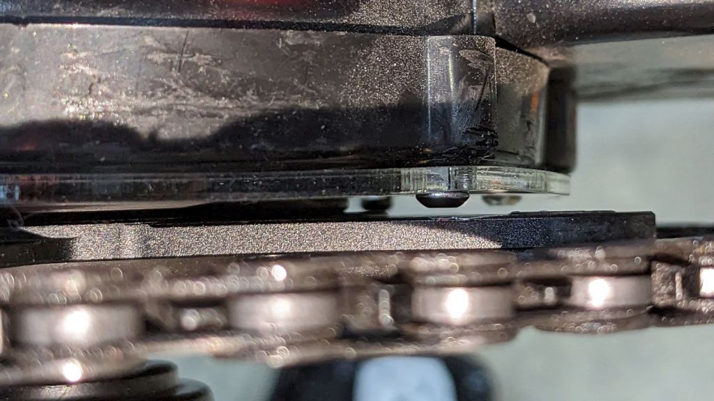
With that in hand, I cut a 1 mm acrylic shape to measure the clearance between the motor + filler and the chainring spider, with pan-head screws replacing the original flat-head screws:
Bafang motor gap filler – top view
That’s a single piece of 2.5 mm acrylic I used after discovering a pair of the 1 mm acrylic shapes fit with space to spare: hooray for rapid prototyping.
A test chain drop suggested it might suffice:
Bafang motor gap filler – test
If I were so inclined, 3 mm acrylic with countersunk holes and slightly longer flat-head screws would probably work, but I’ll use this until it fails to prevent a chain snag.
The careful observer will have noted the stress crack extending radially inward from the upper-right screw, which I am carefully avoiding doing anything about, pending the aforementioned failure.


