Ed Nisley's Blog: Shop notes, electronics, firmware, machinery, 3D printing, laser cuttery, and curiosities. Contents: 100% human thinking, 0% AI slop.
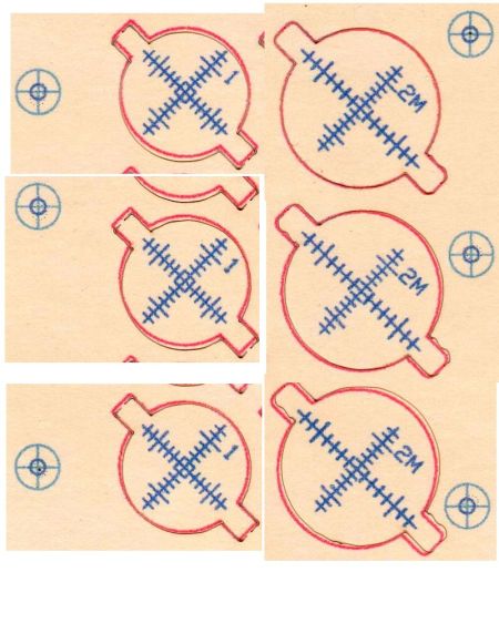
The smaller targets fit neatly into the hole perpendicular to the beam:
OMTech CO2 Mirror 2 mount – Y Z screws
The larger ones sit flush on the mirrors at 45° to the beam, so stretching the horizontal scale by 1.414 = √2 makes each tick mark correspond to 1 mm of perpendicular beam offset.
All of which worked surprisingly well, with some caveats.
The first gotcha: ordinary consumer-grade inkjet printers do not have CNC accuracy. The corner targets are on 150 mm horizontal centers and 240 mm vertical centers in the LightBurn layout, but my Epson ET-3830 printer put them on 150×241.3 mm centers. This isn’t unexpected, particularly for laser printers, but it means you must use LightBurn’s scaled version of the P-n-Cut alignment.
I used the upper-right and lower-left targets for the P-n-Cut alignment step, confirming the positioning with a laser pulse putting a tiny hole in the paper:
Print-and-Cut – target accuracy
The lines are 0.5 mm wide and the inner circle is 2 mm in diameter, so my alignment at the upper right is as good as it’s gonna get and the lower left is off by maybe 0.3 mm. While it may be possible to be more accurate, I think half a millimeter is a reasonable error budget for targeting accuracy.
The laser-perforated circles should overlay the inner printed circles after LightBurn applies the P-n-C corrections. That they obviously do not indicates the effect of the small target errors. In any event, the maximum error seems to be 1 mm, which gives you an idea of just how precise P-n-C might be.
The perimeter laser cuts are off by about the same amount & direction as the dotted circle in the adjacent target:
Print-and-Cut – perimeter matching
Overall, errors around 1 mm seem possible with careful attention to detail, but expecting anything better than a few millimeters is probably unreasonable, particularly for layouts larger than a Letter size page.
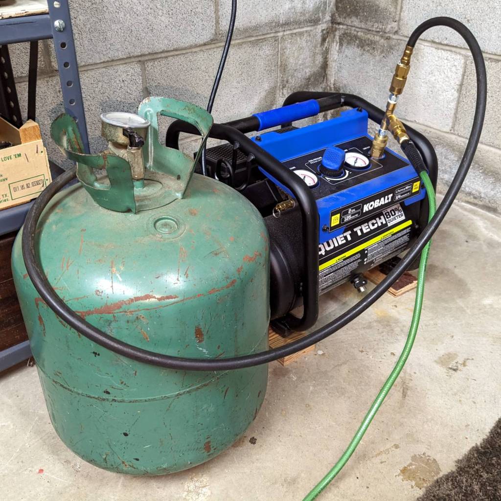
The normal dual-flow assist air setup has a flow control valve (the knob sticking up on the right) normally set for 2 l/min from the air pump:
OMTech Laser – air assist – plumbing
I cranked that valve completely open to allow unrestricted flow with the solenoid (block in the middle) closed and varied the compressor’s output pressure while measuring the air flow.
Without further ado, the assist air flow rate as a function of the inlet air pressure just upstream of the Y fitting on the left:
Assist Air flow vs inlet pressure
Fairly obviously, the flow is not 5.5 l/min at 0 psi inlet pressure and the long & skinny air hose limits the flow above 15 l/min. The eyeballometric line looks pretty good in the middle, though.
Other measurements not shown here suggested the outlet pressure, as measured just downstream of all the plumbing / upstream of the flowmeter & hose to the laser head, is about 1 psi at 10 to 12 l/min flow, with 0.2 psi at 8 l/min. My pressure gauges have terrible accuracy at such low pressures, so I don’t trust those numbers, but the plumbing definitely accounts for most of the inlet-to-outlet pressure drop.
The nozzle on the laser head is 4.1 mm ID → 13.2 mm²:
Magnetic Honeycomb Spikes – MDF
A flow of 10 l/min produces a 13 m/s = 28 mile/hr wind through the nozzle, which seems adequate to blow the fumes out of the kerf, and the low-flow default of 2 l/min might be a 5 mph breeze.
More air pressure would produce more wind, but it’s not clear how much better the resulting cuts would be.
A rear spoke snapped on Mary’s Tour Easy while we were at the far end of a ride. Unlike most broken spokes, the flanged end that I couldn’t maneuver the stub out of the hub and deploy the FiberFix, so we rode home slowly while avoiding as much rough pavement as feasible.
Once in the shop, pulling the sprocket and extracting the stub posed no problem:
Tour Easy broken spoke
Install the new spoke, crank to 23 on the Park Spoke Tension Meter to match the rest of the wheel, check the truing, and it’s all good.
At some point in the last two decades of riding, it seem the chain fell off the high side and gouged the spokes around the hub:
Tour Easy broken spoke – damage
If another spoke snaps in the near future, I’ll replace the lot of them, but until then, well, there’s riding to be done …
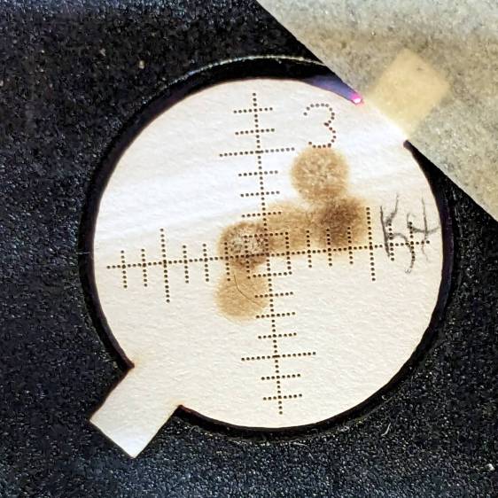
A recent mirror alignment check led to complete failure at the laser head aperture just upstream of Mirror 3:
Beam alignment – M3 fail
Those five spots come from the center of the platform and the four corners; they will overlay into a single spot in a properly aligned machine.
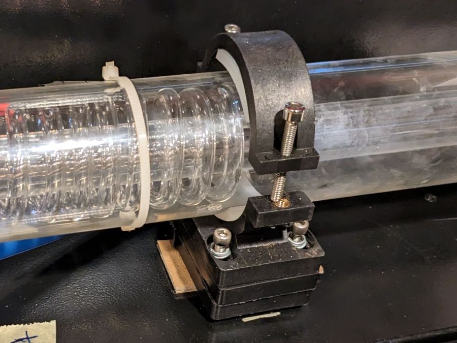
Pondering my options reminded me that I intended to build new laser tube support pads, because the ones shipped inside the machine seemed crudely made:
CO2 Laser supports – OEM hardware
It’s partly disassembled in preparation for the next step.
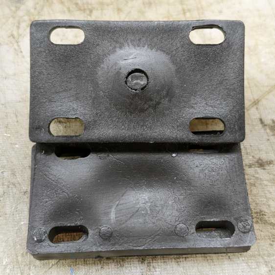
The chipboard shims underneath the stack are mine, but the OEM pile was unstable even with the screws tightened. The reason became obvious when I took the stack apart:
CO2 laser supports – OEM molded parts
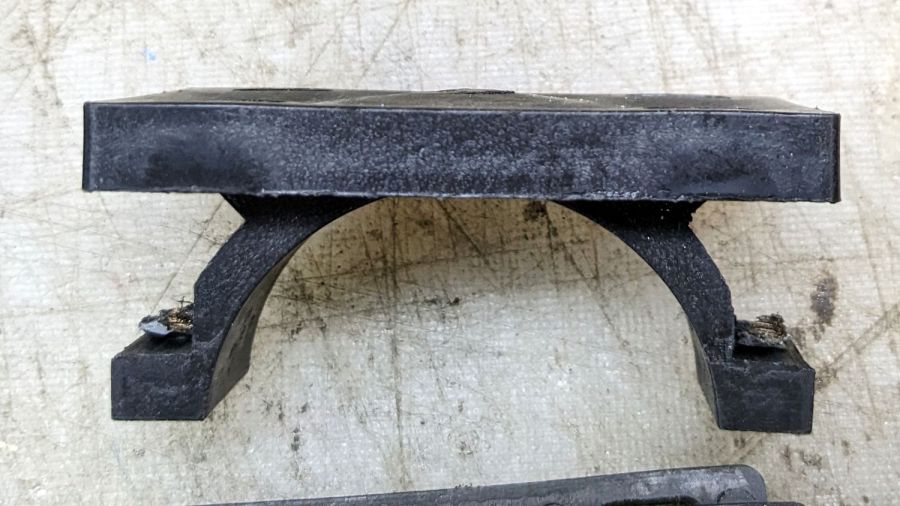
The bump in the middle of the upper block surrounds the post of the laser tube cradle. It looks like this from the side:
CO2 Laser supports – OEM tube cradle – side view
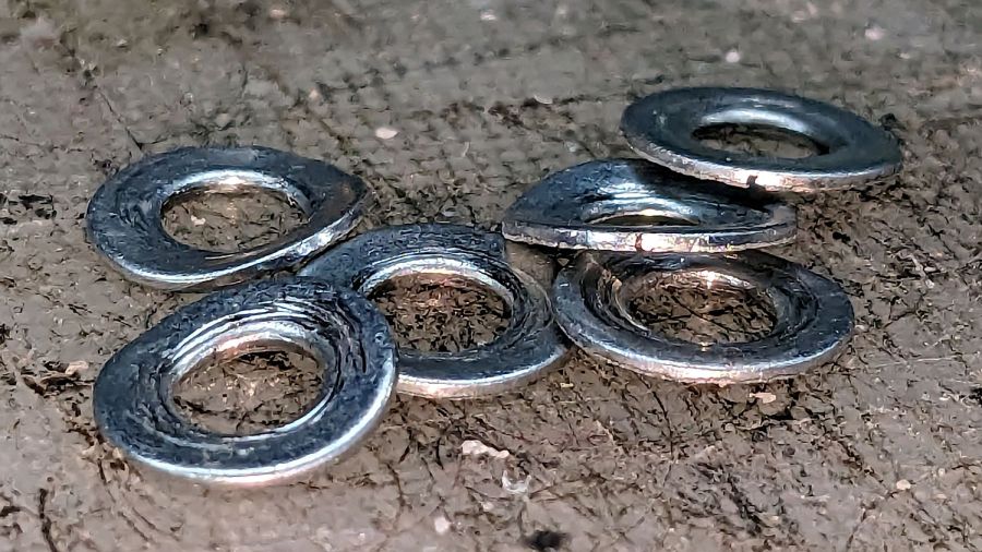
All of the blocks were crudely molded and could not be stacked into a stable pile. The tech who assembled and aligned the machine tightened the screws so firmly that the washers crushed into saddles:
CO2 Laser supports – OEM crushed washers
I can do better than that, if only because I’m not on the clock.
The tube support on the right end (toward the beam outlet) screwed into a nice set of threaded inserts brazed onto the floor of the laser compartment.
As far as I can tell, the laser cabinet was intended for a real 60 W tube measuring 1200 mm that would stick out into a box on the side of the cabinet, but would allow the left tube support base (shown above) to screw into a similar quartet of threaded inserts. Instead, it has an overdriven 50 W tube measuring 1050 mm with the left support screwed into four crudely hand-drilled and -tapped holes so far off the centerline as to jam the screws against the front end of their slots in order to get the tube barely into alignment, with the screws on the output side jammed against the rear end of their slots.
To answer a question you may have: the commercial tube supports one might buy from a reputable supplier (or, for that matter, Amazon) are either exactly as wide as the compartment (thus eliminating one degree of freedom) or obviously unsteady, and would surely require drilling more holes in awkward locations.
So, we begin.
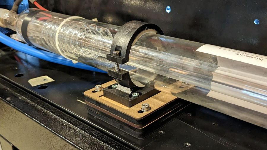
The general idea is to make a larger set of blocks fitting another quartet of holes with threaded inserts on the right side of the compartment floor:
CO2 Laser supports – installed right
On the right, I stuck the bottom block to the shelf with double-sided tape:
CO2 Laser supports – installed left
Because I was unwilling to:
Drill and tap holes with the tube in place or
Remove the tube to get safer access
The alert reader will note the four tapped holes immediately to the right of the new blocks. Those were evidently intended for a center tube support for the longer tube, because the crudely hand-drilled holes hide just out of view to the left of the new blocks.
At the far left of that picture, beyond the two holes probably intended for coolant tubes, you can see one of the four holes with tapped inserts that would match longer tubes, where the 50 W tube has its anode and coolant connections.
The larger blocks I made have a hole accommodating the bulge in the tube cradle to let it slide back and forth as needed:
CO2 Laser supports – gluing top layers
That seemed easier and less exciting than attempting to flycut the bottom of the OEM plastic tube cradle.
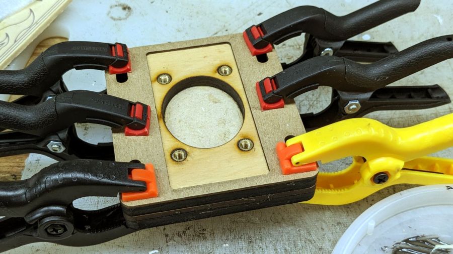
The chipboard layer serves as a guide to keep the tube cradle lined up, with its now much shorter screws into the brass inserts epoxied into the plywood layer.
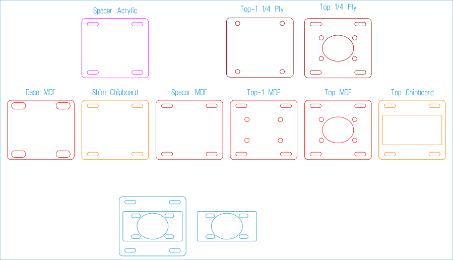
I glued the top layers together to get a rigid assembly, with the lower layers being replaceable shims adding up to the right height, whatever that might be. The LightBurn layout has an assortment of useful pieces, some of which I didn’t need:
Laser tube support blocks – LightBurn layout
If this were a greenfield project, the leftmost Base MDF pad would come in handy, as its slots are large enough to clear the flat side of the 4 mm rivnuts I’d install in the compartment floor.
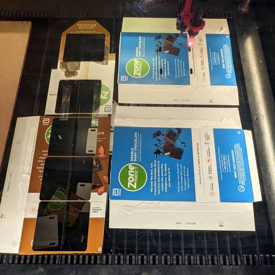
Thin shims come from paperboard boxes & chipboard:
CO2 Laser supports – thin shims
Thicker spacers come from (scrap) plywood and MDF:
CO2 Laser supports – thIck shims
Skipping ahead a few days, the tube & mirror realignment came out much better:
Alignment at Mirror 3 – four corners – 2023-09-02
That’s only the four corners of the platform, but it’s OK by me.
If you’re fussy, the scorches are all low by a bit under 2 mm. Fixing that requires raising the tube by 2 mm, which I can certainly do, but I’m going to let this whole affair mellow out for a while.
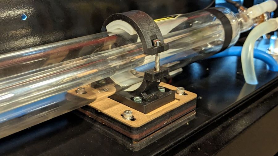
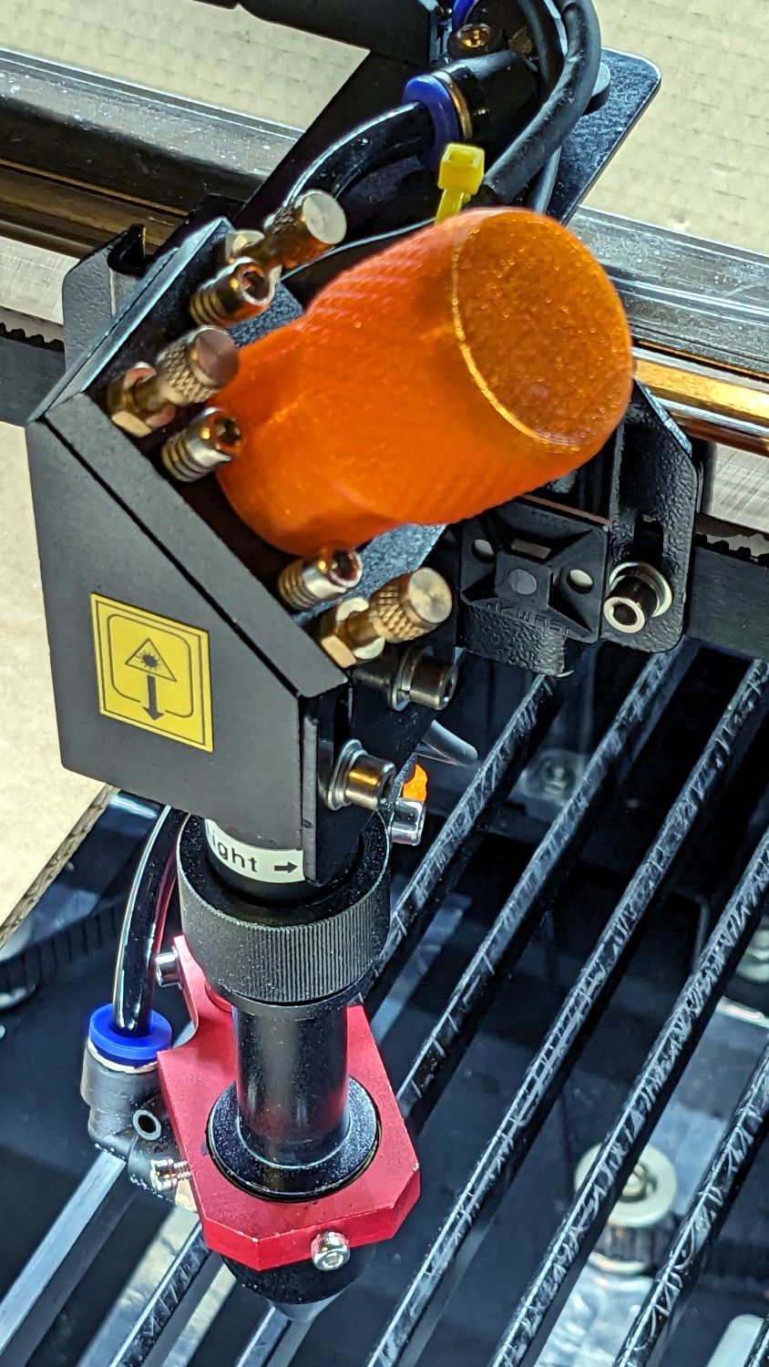
After struggling with pin pliers again, I finally made a pin wrench for the laser cutter’s mirror retaining rings:
Laser Mirror Pin Wrench – in use
The odd grayish tint toward the flat end of the knob comes from residual black filament in the hot end after switching to retina-burn orange PETG.
The solid model looks about like you’d expect:
Mirror Pin Wrench – Solid Model
The pins are snippets of 3/32 inch = 2.4 mm steel rod with ground-round ends to fit the 2.5 mm pin sockets in the retaining ring.
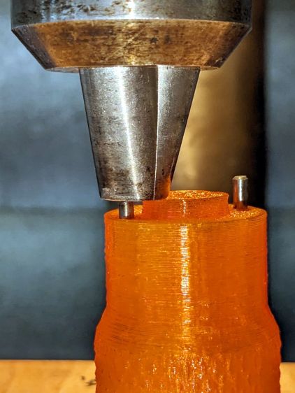
They’re rammed into place with a drill press to keep them aligned with the holes:
Laser Mirror Pin Wrench – pin insertion
Pressed flush with the central boss that aligns the wrench with the ring:
Laser Mirror Pin Wrench – pin leveling
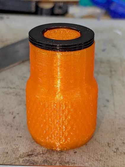
Then put the ring on the bench, set the wrench atop the ring with the pins in the sockets, and press firmly to seat the pins to the proper depth. The end results should look like this:
Laser Mirror Pin Wrench – mirror ring test
The next time I clean the mirrors, there will be less muttering.
This file contains hidden or bidirectional Unicode text that may be interpreted or compiled differently than what appears below. To review, open the file in an editor that reveals hidden Unicode characters.
Learn more about bidirectional Unicode characters
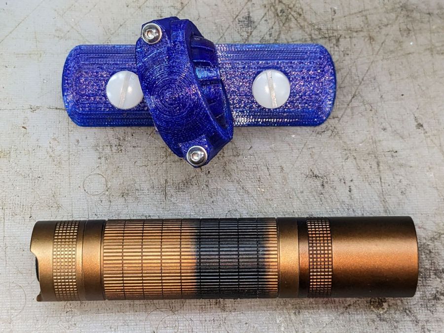
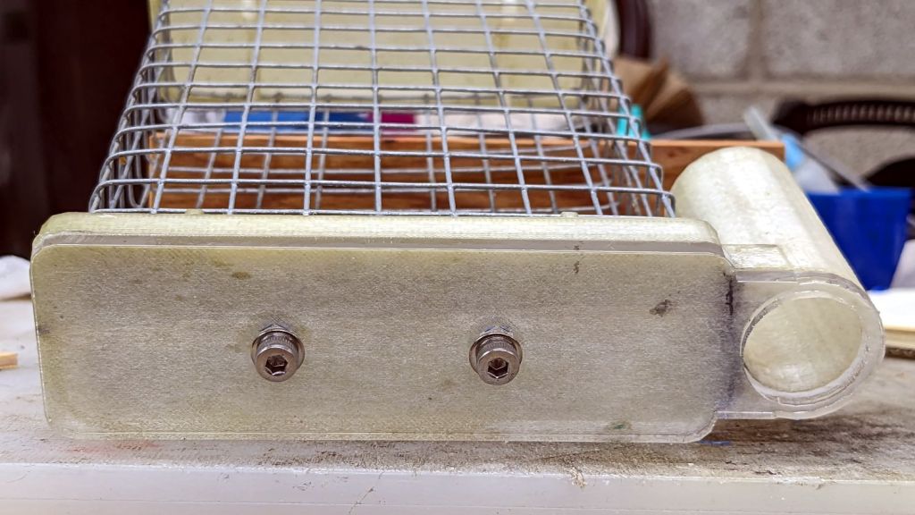
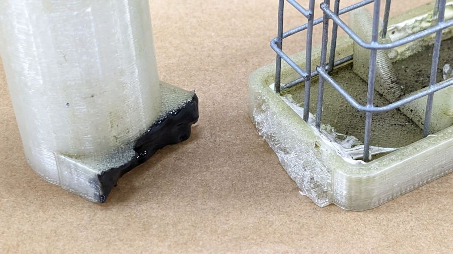
One of the sticky traps absorbed a mighty blow during the season and its ski-pole mount snapped off. Rather then rebuild the whole thing, I decided to just epoxy the pieces together and stick a reinforcing plate on the bottom.
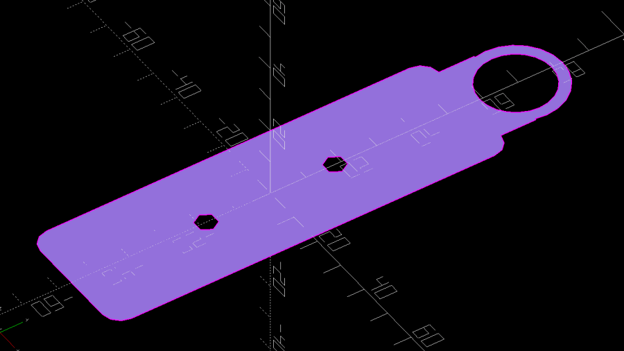
I added a pair of screw holes to the OpenSCAD model and produced a projection of the bottom layer:


