|
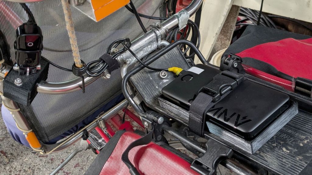
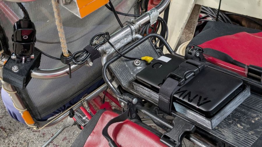
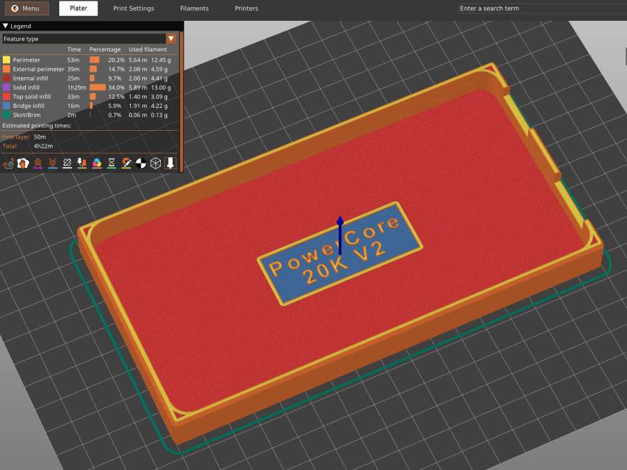
// Anker PowerCore 325 20K V2 Power Bank |
|
// Ed Nisley – KE4ZNU |
|
// 2024-07 |
|
|
|
/* [Layout Options] */ |
|
|
|
Layout = "Show"; // [Show,Build] |
|
|
|
Part = "Cradle"; // [Cradle,Battery,Pad] |
|
|
|
|
|
/* [Extrusion Parameters] */ |
|
|
|
ThreadWidth = 0.40; |
|
ThreadThick = 0.25; |
|
|
|
HoleWindage = 0.2; |
|
|
|
Protrusion = 0.1; |
|
|
|
//—– |
|
// Dimensions |
|
|
|
/* [Hidden] */ |
|
|
|
ID = 0; |
|
OD = 1; |
|
LENGTH = 2; |
|
|
|
EmbossDepth = 2*ThreadThick + Protrusion; // recess depth + Protrusion beyond surface |
|
|
|
DebossHeight = EmbossDepth; // text height + Protrusion into part |
|
|
|
Projection = 10; // stick-out to punch through shell sides & suchlike |
|
|
|
FadeColor = "Green"; |
|
FadeAlpha = 0.25; |
|
|
|
//—– |
|
// Useful routines |
|
|
|
function IntegerMultiple(Size,Unit) = Unit * ceil(Size / Unit); |
|
|
|
module PolyCyl(Dia,Height,ForceSides=0) { // based on nophead's polyholes |
|
|
|
Sides = (ForceSides != 0) ? ForceSides : (ceil(Dia) + 2); |
|
|
|
FixDia = Dia / cos(180/Sides); |
|
|
|
cylinder(r=(FixDia + HoleWindage)/2, |
|
h=Height, |
|
$fn=Sides); |
|
} |
|
|
|
|
|
//—– |
|
// Battery |
|
// Based on Anker PowerCore 325, simplified shapes |
|
// Includes port punchouts |
|
|
|
Battery = [162.0+0.5,81.5+0.5,24.0]; // X=length, Y=max, Z=max |
|
|
|
module BatteryShape(Jacks = true) { |
|
|
|
USB = [[Projection,20,12],[Projection,18,10]]; // clearance around USB output jacks |
|
USBOffset = [[0,20.0,0],[0,62.5,0]]; // from -Y edge to center of jack, Z centered |
|
|
|
BatteryRad = 7.0; // corner rounding radius |
|
BatterySides = 2*3*4; |
|
|
|
hull() |
|
for (i=[-1,1], j=[-1,1]) |
|
translate([i*(Battery.x/2 – BatteryRad), |
|
j*(Battery.y/2 – BatteryRad), |
|
0]) |
|
cylinder(r=BatteryRad,h=Battery.z,$fn=BatterySides,center=true); |
|
if (Jacks) |
|
for (i=[0,len(USB)-1]) |
|
translate([(Battery.x + USB[i].x)/2 – Protrusion,-Battery.y/2 + USBOffset[i].y,0]) |
|
cube(USB[i],center=true); |
|
} |
|
|
|
//—– |
|
// Battery cradle |
|
|
|
RackWidth = 90.0; // flat width between rack rails |
|
|
|
CradleWall = [4.0,4.0,3.0]; // wall thickness |
|
CradleRadius = 2.0; // corner rounding |
|
|
|
CradlePad = 1.0; // cushion on battery bottom |
|
BatteryBase = CradleWall.z + CradlePad; // actual bottom surface of battery |
|
|
|
CradleOA = [Battery.x + 2*CradleWall.x, |
|
min((Battery.y + 2*CradleWall.y),RackWidth), |
|
BatteryBase + Battery.z/2]; |
|
echo(str("Cradle OA: ",CradleOA)); |
|
|
|
module Cradle() { |
|
|
|
difference() { |
|
hull() |
|
for (i=[-1,1], j=[-1,1]) { // box with tidy rounded corners |
|
translate([i*(CradleOA.x/2 – CradleRadius), |
|
j*(CradleOA.y/2 – CradleRadius), |
|
1*(CradleOA.z – CradleRadius)]) |
|
sphere(r=CradleRadius,$fn=6); |
|
translate([i*(CradleOA.x/2 – CradleRadius), |
|
j*(CradleOA.y/2 – CradleRadius), |
|
0*(CradleOA.z/2 – CradleRadius)]) |
|
cylinder(r=CradleRadius,h=CradleOA.z/2,$fn=6); |
|
} |
|
|
|
translate([0,0,Battery.z/2 + BatteryBase]) // minus the battery |
|
minkowski(convexity=3) { // … slightly embiggened |
|
BatteryShape(); |
|
cube(2*CradlePad,center=true); |
|
} |
|
|
|
translate([0,0,CradleWall.z – ThreadThick + Protrusion/2]) // recess top legend |
|
cube([55,20,EmbossDepth],center=true); |
|
translate([0,0,(EmbossDepth – Protrusion)/2]) // recess bottom legend |
|
cube([70,15,EmbossDepth],center=true); |
|
} |
|
|
|
translate([0,4.0,CradleWall.z – DebossHeight – Protrusion]) |
|
linear_extrude(height=DebossHeight,convexity=20) |
|
text(text="PowerCore",size=6,spacing=1.20, |
|
font="Arial:style:Bold",halign="center",valign="center"); |
|
|
|
translate([0,-4.0,CradleWall.z – DebossHeight – Protrusion]) |
|
linear_extrude(height=DebossHeight,convexity=20) |
|
text(text="20K V2",size=6,spacing=1.20, |
|
font="Arial:style:Bold",halign="center",valign="center"); |
|
|
|
linear_extrude(height=DebossHeight,convexity=20) |
|
mirror([0,1,0]) |
|
text(text="KE4ZNU",size=10,spacing=1.20, |
|
font="Arial:style:Bold",halign="center",valign="center"); |
|
|
|
|
|
} |
|
|
|
|
|
//—– |
|
// Build things |
|
|
|
// Layouts for design & tweaking |
|
|
|
if (Layout == "Show") |
|
|
|
if (Part == "Battery") |
|
BatteryShape(); |
|
|
|
else if (Part == "Cradle") { |
|
Cradle(); |
|
translate([0,0,Battery.z/2 + CradleWall.z]) |
|
color(FadeColor,FadeAlpha) |
|
BatteryShape(); |
|
} |
|
|
|
else if (Part == "Pad") |
|
linear_extrude(height=CradlePad) |
|
projection(cut=true) |
|
BatteryShape(Jacks = false); |
|
|
|
|
|
|
|
// Build layouts for top-level parts |
|
|
|
if (Layout == "Build") { |
|
|
|
if (Part == "Cradle") |
|
Cradle(); |
|
|
|
if (Part == "Pad") |
|
projection(cut=true) |
|
BatteryShape(Jacks = false); |
|
|
|
} |
|
|