Starting from the Pyrotechnics quilt block on page 132 of Beyer’s book:

It looks more like flowers than fireworks to me, but there’s no accounting for taste.
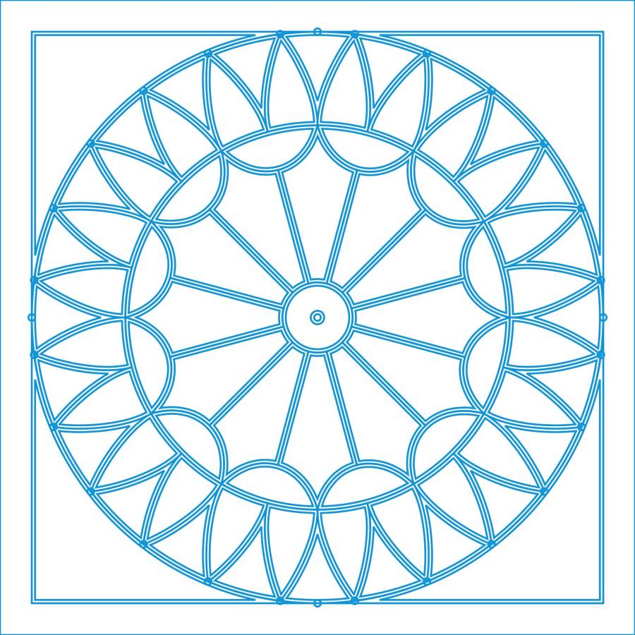
Deploy enough 2 mm circles to catch the flower’s radial symmetry:
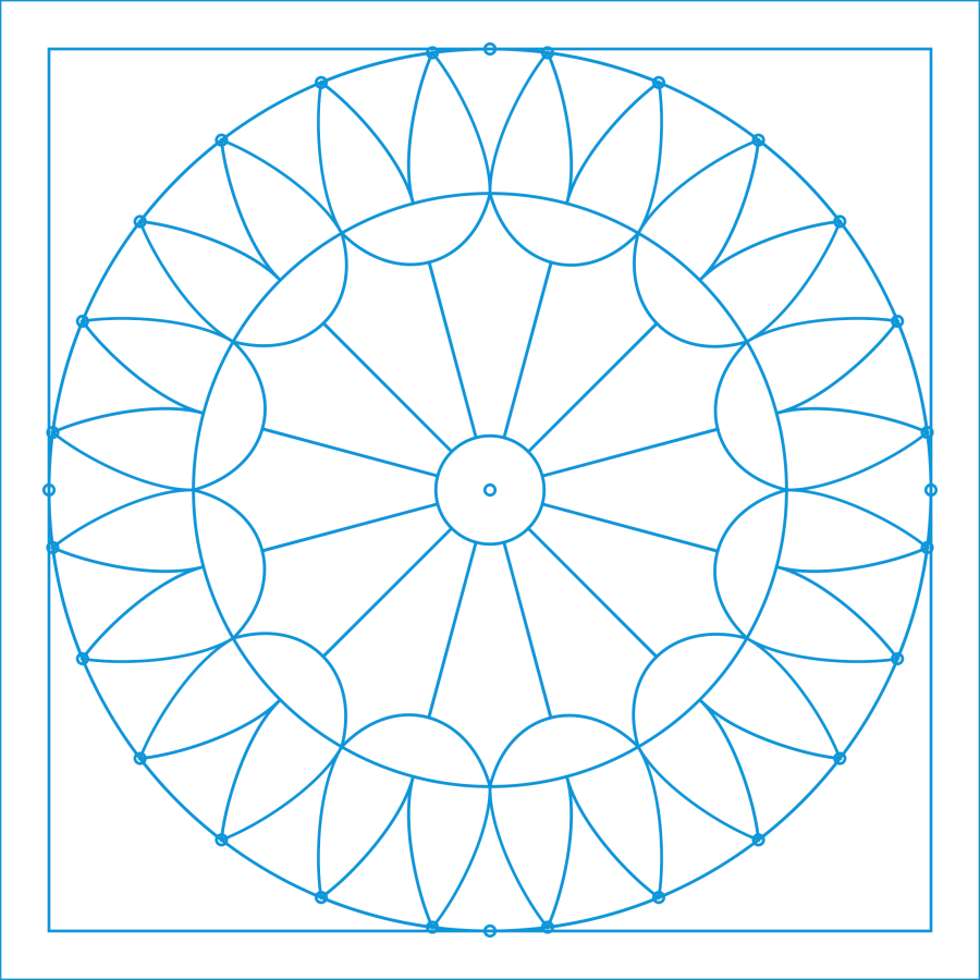
During the process of building the layout, a big circle positioned the cups at the base of the flowers, another delineated the joint between the cups and the petals, and more little circles caught the intersection of those circles with the petals. All that was for visualization and positioning, as you only draw one flower shape, then duplicate it around the pattern.
Although the cups and petals are surely circular arcs, it’s easier to draw a closed line triangle around the intersections, then pull the midpoint of a line into an arc (Bezier curve!) matching the pattern Closely Enough™ at high zoom. Because the arcs end at the intersection points based on circular arrays of points, they’ll all match up when they’re duplicated around the pattern; in fact, you need only one side of one petal, mirror it around the midline, and away you go.
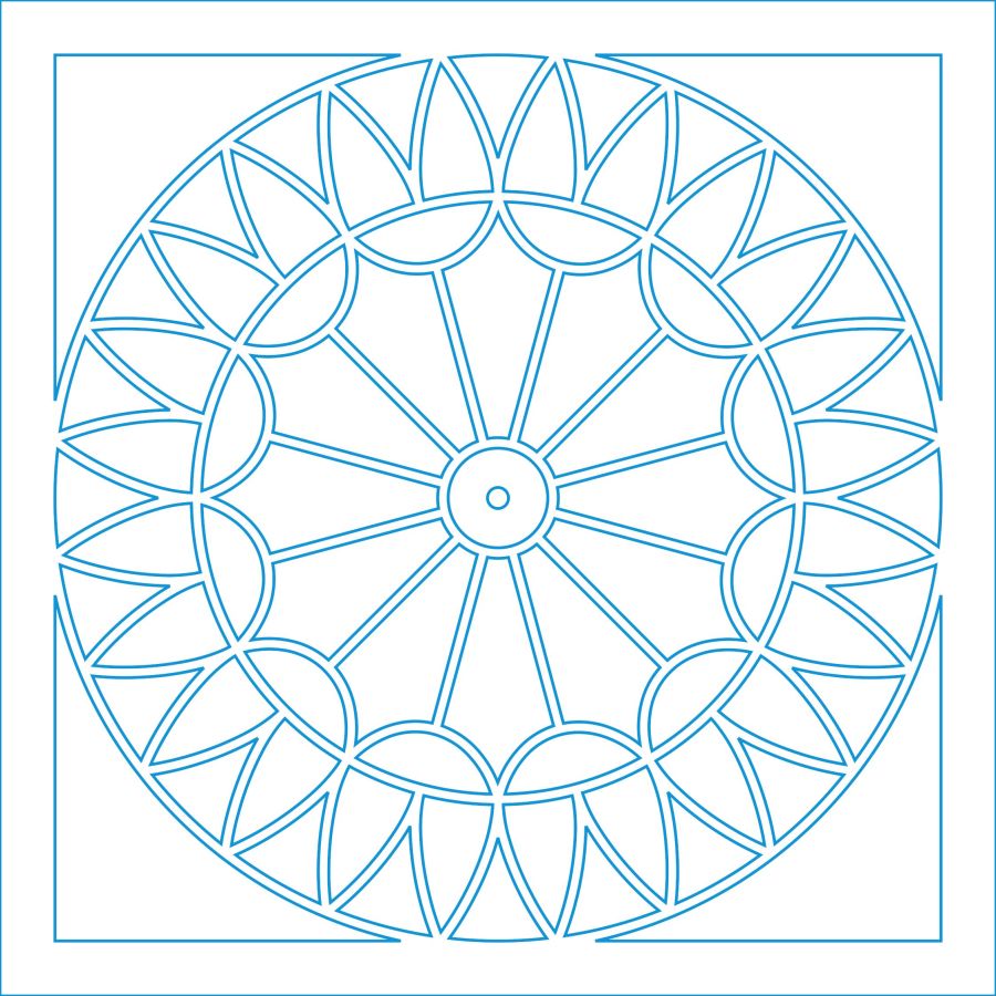
Then the magic happens:
Which is easier to see without the original shapes:
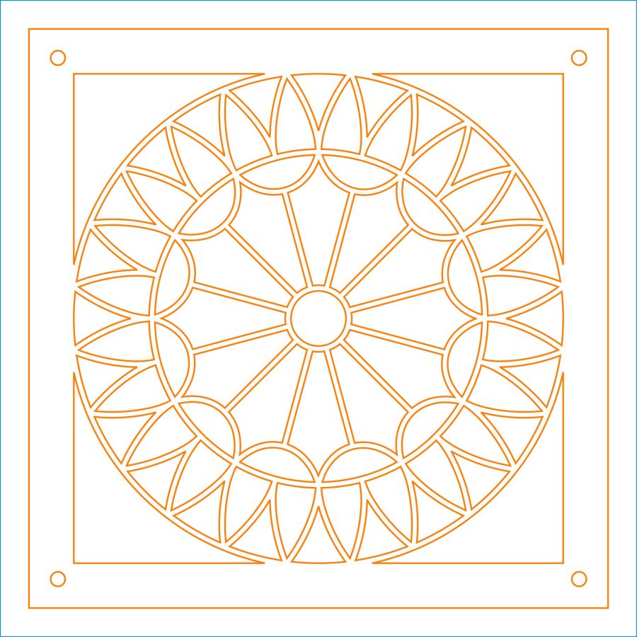
Pick one of the closed shapes, apply the Offset tool to shrink it by 1 mm, duplicate as needed, and you get the outlines of the regions to cut with 2 mm between them. Plunk those shapes on a cutting layer, add the outer frame with locating holes for the fixture, and it’s ready to cut the top layer from black paper:
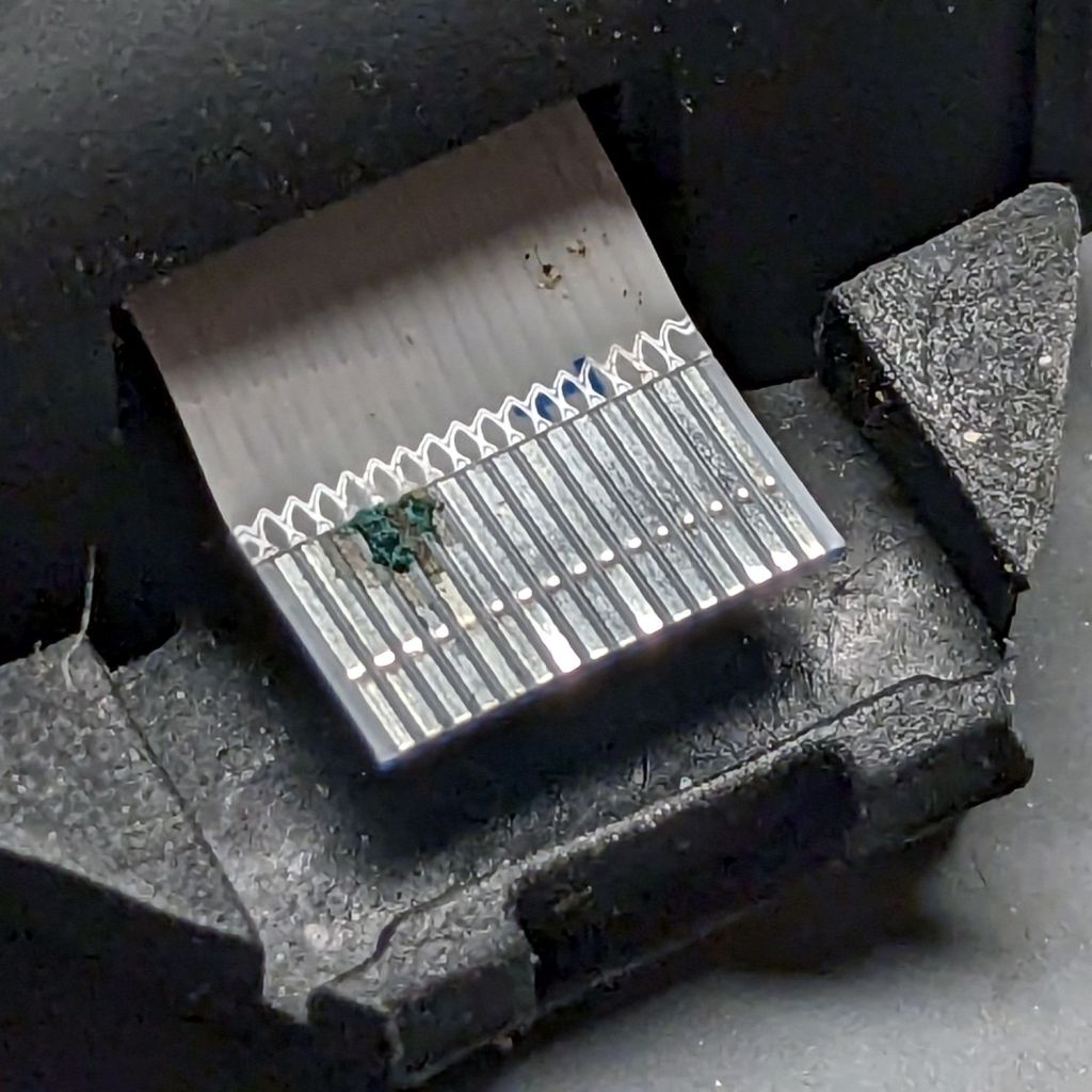
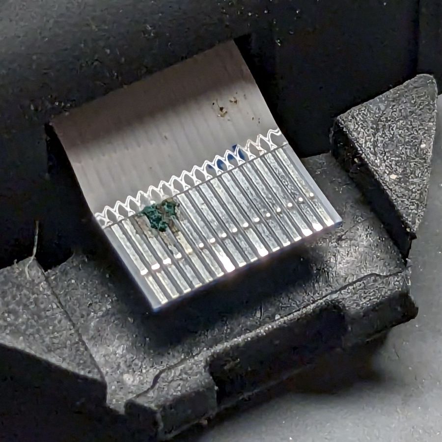
Knock out the cuts for each sheet of paper in the stack:
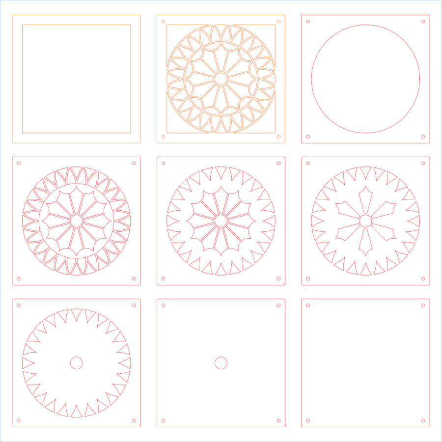
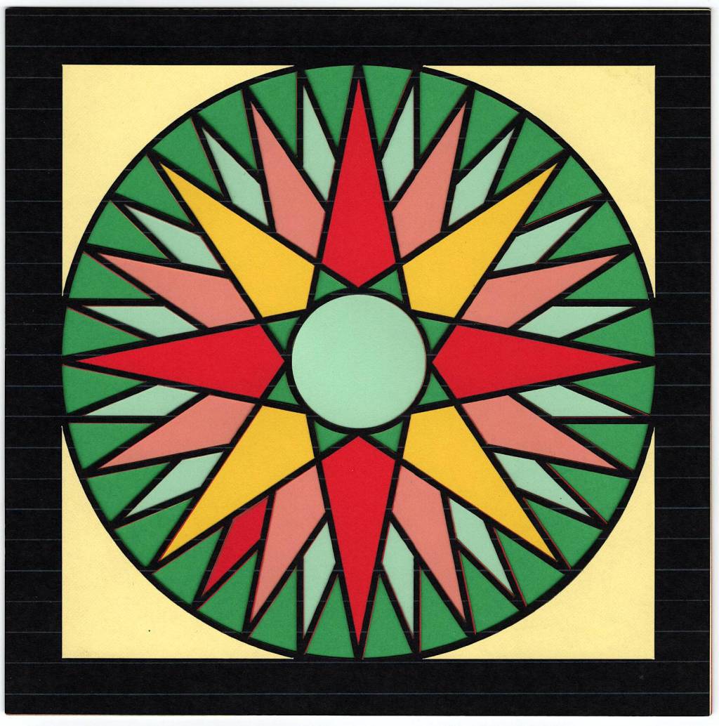
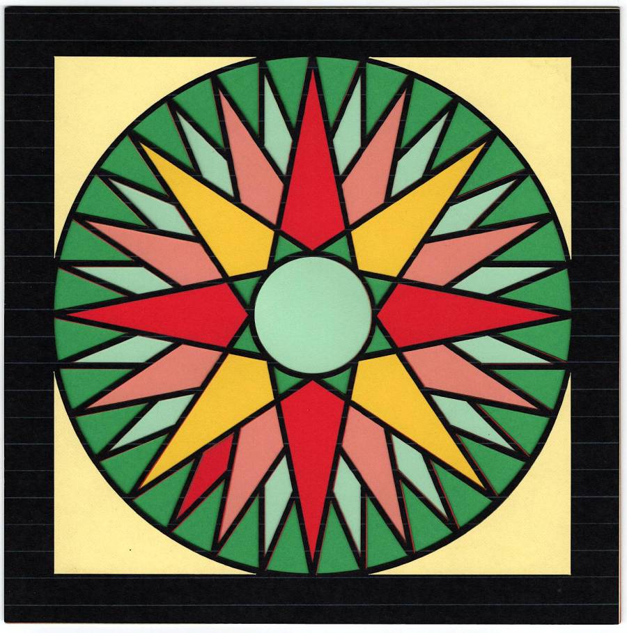
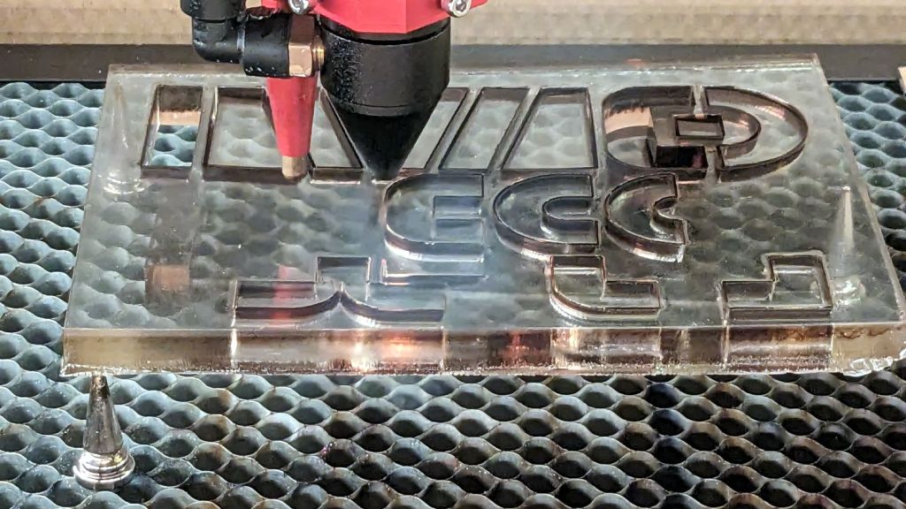
Then Fire The Laser™:
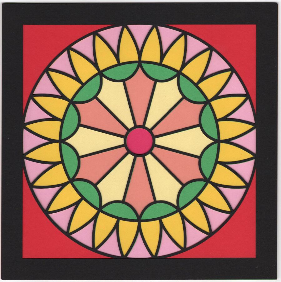
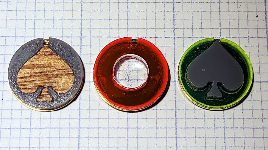
That was a nearly random selection of colors, but it’s hard to go wrong.
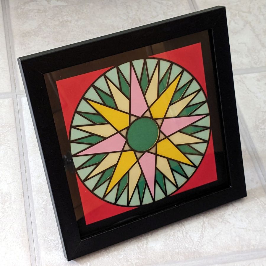
IMO, a frame makes it look even better:

This could be Art.