The Smell of Molten Projects in the Morning

Ed Nisley's Blog: Shop notes, electronics, firmware, machinery, 3D printing, laser cuttery, and curiosities. Contents: 100% human thinking, 0% AI slop.

Category: Machine Shop

Mechanical widgetry

  • Sears Sewing Machine Table Latch Fix

    Sears Sewing Machine Table Latch Fix

    The Sears sewing table (Model 853-9635, not that you have one) wrapped around Mary’s Kenmore machine has extension surfaces on both ends:

    Sears Sewing Machine Table - overview
    Sears Sewing Machine Table – overview

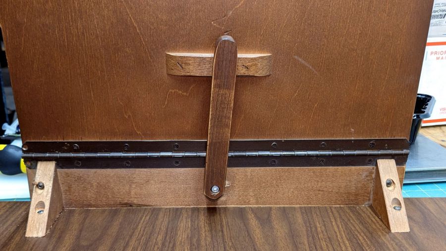
    The foot panel is secured by a simple wood latch that fell off the left side:

    Sears Sewing Machine Table - stripped hole
    Sears Sewing Machine Table – stripped hole

    Having some recent experience with this sort of thing, but not wanting to work under there, I waited for a pause in the sewing, then tried to remove just the hinged piece under the top surface. It turns out the joint is glued-and-screwed, so removing the two obvious screws didn’t do anything.

    Dismounting the top surface at its other hinge and hauling the whole assembly to the Basement Shop showed this wasn’t the first time the latch had pulled its pivot screw out of the wood:

    Sears Sewing Machine Table - stripped hole detail
    Sears Sewing Machine Table – stripped hole detail

    The reason the screw pulled out of the top hole / slot is obvious when seen from the edge:

    Sears Sewing Machine Table - screw obstruction
    Sears Sewing Machine Table – screw obstruction

    That’s one of the screws holding the piano hinge in place, but AFAICT the original latch screw also went right across that hole with maybe three threads engaging the wood.

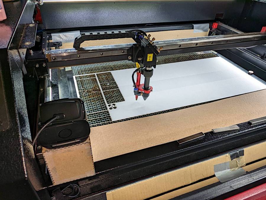
    Moving the pivot half an inch to one side won’t make any difference, so I figured I could sink a threaded insert into the wood. I’d rather use the drill press, but sometimes you gotta do what you gotta do:

    Sears Sewing Machine Table - insert drilling
    Sears Sewing Machine Table – insert drilling

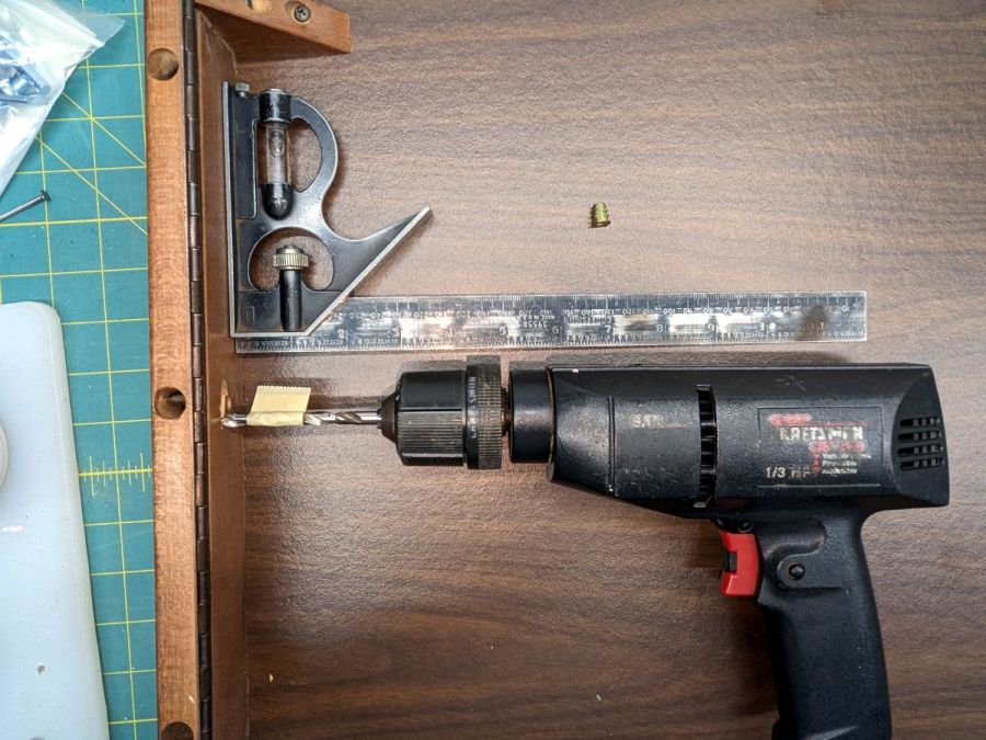
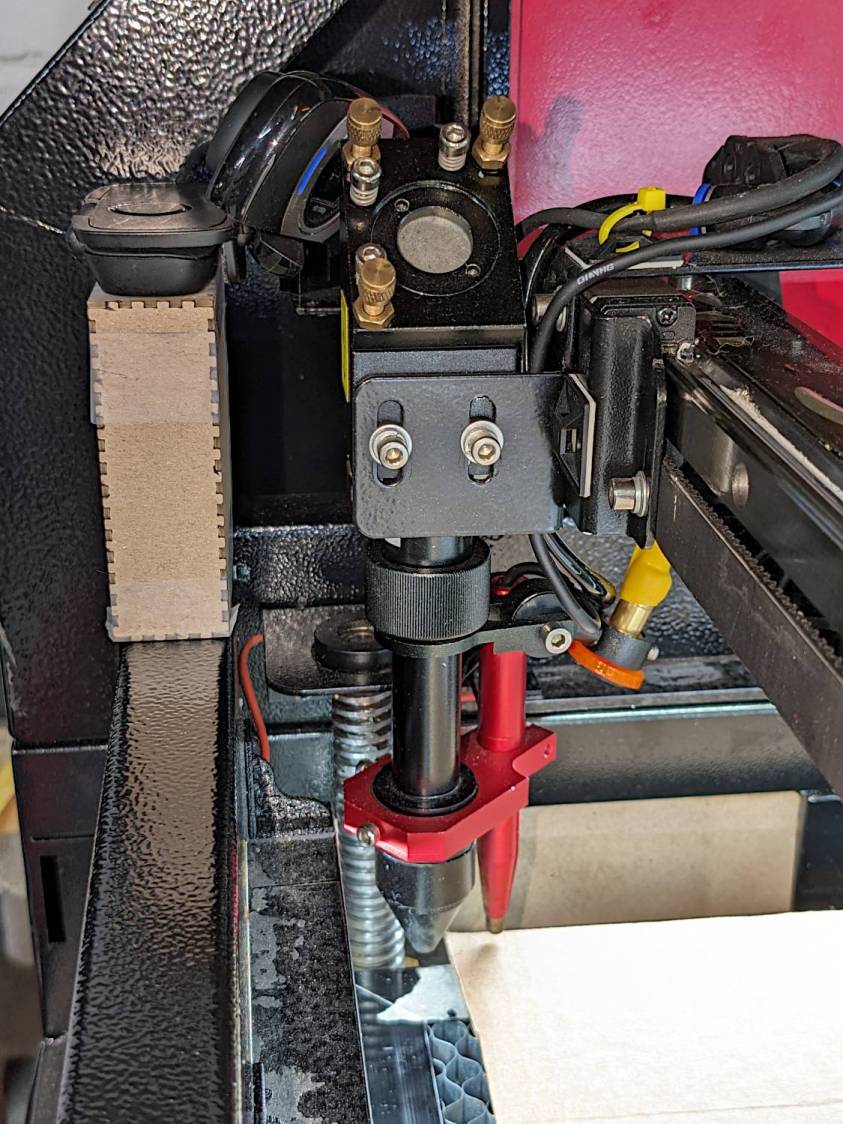
    The combination square gets the drill eyeballometrically perpendicular to the end piece and the drill lies flat on the (underside) of the table surface. Seeing the bit line up with where the hole had to be was confirmation this would be successful; all I had to do was proceed slow-n-steady with the brad-point bit and stop when the tape hit the wood.

    The insert screwed in as expected, without any collisions:

    Sears Sewing Machine Table - insert installed
    Sears Sewing Machine Table – insert installed

    I drilled the wood latch to clear an M5 screw on the drill press, dabbed the screw with threadlocker, and reassembled everything on the bench for curing:

    Sears Sewing Machine Table - latch installed
    Sears Sewing Machine Table – latch installed

    The extension surface on the right side of the table has an identical latch that hasn’t failed yet, but we agreed a preemptive repair is uncalled for.

    The WordPress AI image generator is delivering much less jank, even if the result has little to do with the actual post:

    Sears Sewing Table - WP AI image
    Sears Sewing Table – WP AI image

    Don’t think too much about the shadows, nor the lack of a treadle for what looks a lot like an early Singer Featherweight machine.

  • Magnifying Desk Light: LED-ifying & Base Refooting

    Magnifying Desk Light: LED-ifying & Base Refooting

    My ancient fluorescent magnifying desk lamp emerged from a box and cried out to be used, but the equally ancient 22 W fluorescent ring light was long past its prime and cried out to be replaced with something from the current millennium.

    So I removed the fluorescent ballast / choke from the junction box at the lamp base:

    Magnifying Ring Light - ballast removed
    Magnifying Ring Light – ballast removed

    That’s a grounded outlet in the cover plate serving as a wire termination block. The red crimp connector joins a white wire that formerly went to the ballast with the black wire going to the lamp head; you’ll note the black wire from the line cord going into the same heatstink tubing at the outlet.

    The lamp head had a push-to-start switch, presumably with an internal starting capacitor or some such, but also sporting a pair of terminals behaving like a single-pole push-on / push-off switch. A bit of rewiring, of which there are no pictures, made it work perfectly with the new 13 W LED ring light:

    Magnifying Ring Light - LED ring installed
    Magnifying Ring Light – LED ring installed

    It now sits on a bit of laboratory ironmongery weighing about as much as a small child:

    Magnifying Ring Light - on base
    Magnifying Ring Light – on base

    Although the base has four feet, it sits perfectly flat on my (admittedly battered) surface plate because all four feet have been ground to make that happen:

    Magnifying Ring Light - foot plan view
    Magnifying Ring Light – foot plan view

    Those feet will be hostile to any table / bench top outside their intended laboratory environment. Fortunately, the geometry is simple enough to build directly in LightBurn and cut from a cork disk with PSA backing suited to become a coaster:

    Magnifying Ring Light - cork foot cutting
    Magnifying Ring Light – cork foot cutting

    Which fit well enough, although all four feet are just slightly different:

    Magnifying Ring Light - cork foot
    Magnifying Ring Light – cork foot

    The new Basement Shop™ is coming together and this stuff is getting easier …

    The WordPress AI came up with a plausible steampunk build:

    Magnifying Ring Light - WP AI image 1
    Magnifying Ring Light – WP AI image 1

    Love those flowy feet, although the vertical rod in the back seems misplaced.

    Adding “one-piece base” to the prompt produces contemporary style:

    Magnifying Ring Light - WP AI image 2
    Magnifying Ring Light – WP AI image 2

    Dunno what the dingus on the lower arm might be (perhaps a spring?), but it’s got the right general idea.

  • Plywood Clamp

    Plywood Clamp

    Being in need of a dedicated clamp, I made one from Thingiverse:

    Plywood clamp - overview
    Plywood clamp – overview

    The original gets its clamping force from a gazillion rubber bands, but two wraps of shock cord joined by the guts of an electrical crimp connector worked for my simple needs:

    Plywood clamp - shock cord crimp connector
    Plywood clamp – shock cord crimp connector

    The rounded tips work at any thickness, but introducing them to Ms Belt Sander set them for the specific purpose I have in mind:

    Plywood clamp - flatted tips
    Plywood clamp – flatted tips

    The little cork pads are hand-cut from scraps, because why not.

    Rubbing paraffin (wax, not kerosene) on the circular joint’s bearing surfaces makes the hinge move soooo smoothly.

    The WordPress AI image generator is trying much harder:

    Plywood clamp - WP AI Image
    Plywood clamp – WP AI Image

    The callouts almost make sense, because they’re now ripped from the post text. For sure, I will “crustorilize” my next shop project.

    Gotta love the AI evaluation:

    The content shows a practical and creative approach to making a plywood clamp, supported by clear images. Consider adding a brief introduction to provide context for the project. Additionally, explaining the specific purpose for which the clamp is intended would further engage readers. The use of humor and informal language adds a personal touch, enhancing the connection with the audience. Overall, the engaging content and visual aids make it a compelling read.

  • Laser Cutter: Streaming Camera Support

    Laser Cutter: Streaming Camera Support

    If I’m making something with the laser cutter during a Zoomed SquidWrench meeting, switching the view to a camera inside the cabinet is always a crowd-pleaser. Having tried several locations with various degrees of success, the camera now sits atop a small chipboard box holding it as high as it can get over the front left corner of the platform:

    Laser camera support box - position overview
    Laser camera support box – position overview

    It juuuust barely kisses the head in that corner:

    Laser camera support box - near collision
    Laser camera support box – near collision

    The box is a simple ClosedBox from boxes.py with a jawbreaker URL full of parameters, minus two holes, plus a quartet of shims, all cut from chipboard:

    Camera Support box - LB layout
    Camera Support box – LB layout

    The holes fit a 1/4-20 button head screw for the Logitch C615 camera’s tripod mount and the hex wrench needed to tighten it:

    Laser camera support box - interior
    Laser camera support box – interior

    The box is held together with Genuine Scotch Tape, because I want it to fall apart if it gets hit by the laser head. It’s held to the cabinet with a finger-crushingly strong bar magnet.

    The camera has a reasonably good view of the entire platform:

    Laser Cutter - USB Camera view
    Laser Cutter – USB Camera view

    The camera’s closest focus point sits about halfway across the platform, roughly corresponding to the typical monitor-to-face distance the camera was intended for, but it’s Good Enough™ for the purpose.

  • Harbor Freight Bar Clamp: Plywood Handle

    Harbor Freight Bar Clamp: Plywood Handle

    After only a dozen years, one of the 3D printed replacement handles for my Harbor Freight bar clamps snapped exactly where you’d expect:

    HF bar clamp - plywood handle
    HF bar clamp – plywood handle

    The replacement this time around is laser-cut plywood, with a pair of 3 mm sheets glued together to just about match the original thickness:

    HF bar clamp - plywood handle gluing
    HF bar clamp – plywood handle gluing

    I hacked the OpenSCAD code to use its projection() operation to export the outline of the solid model on the XY plane, inhaled the SVG into LightBurn, replaced the original chunky hole with a Real Circle, cut a pair of them, discovered I messed up the diameter, tweaked that, cut a pair that fit perfectly, and that was that.

    Flushed with success, I cut another pair to replace the (not yet failed) handle in the other HF bar clamp and restarted the failure clock.

    Not as fancy as something milled on the Sherline, but way easier and, if it lasts another decade, I’ll call it a win.

    The WordPress AI had fun with this post:

    HF Bar Clamp Handle - WP AI image
    HF Bar Clamp Handle – WP AI image

    The thing over on the left must be a 3D printer, but what’s floating in the middle? Those hand tools look downright scary.

  • Plumb Bobs: Kevlar Lines

    Plumb Bobs: Kevlar Lines

    Having had considerable success re-stringing the seat on Mary’s Tour Easy with Kevlar line, this seemed like a good idea:

    Plumb bobs - Kevlar braided line
    Plumb bobs – Kevlar braided line

    They’re a pair of plumb bobs I’ve had forever, with ten feet of 100 pound Kevlar line in place of their original (and well-worn) string. The key parameter is the 1 mm diameter to fit the holes in the bobs, with the 20 pound working strength being grossly overqualified.

    Because it’s braided line, the bobs no longer spin merrily when deployed, which is a major win.

    They hibernate in pill bottles during their downtime, where the line doesn’t get nearly as tangled as you might imagine.

    Admittedly, I don’t deploy plumb bobs all that often, but in recent months I have needed to know what was directly below something else often enough to remind me to get this done.

    The WordPress AI image for this post is, as usual, disturbing:

    Plumb Bobs - WP AI image
    Plumb Bobs – WP AI image

    I like the perfectly rendered gibberish text. Is that a bizarre spade drill in the lower left? So many pills!

  • Home Depot Glacier Faucet Re-alignment

    Home Depot Glacier Faucet Re-alignment

    The kitchen sink faucet came from the Home Depot Glacier line:

    HD Glacier Bay kitchen faucet - overview
    HD Glacier Bay kitchen faucet – overview

    A “FastMount” push-and-turn nut secures the central pillar to the deck, although it had worked loose since it was installed some years ago. After retightening the nut, however, the faucet spout and handle remained loose, which I eventually figured out was due to the central pillar having worked loose from the plastic body inside the spout.

    The solution involved releasing the FastMount nut, pulling the whole affair out of the deck, and tightening the threaded pillar into the body. After a few false starts, I applied a pair of grippy leather gloves and a firm grasp to twist the pillar another quarter turn into the body, after which it installed properly:

    HD Glacier Bay kitchen faucet - realigned
    HD Glacier Bay kitchen faucet – realigned

    The mark on the far left shows how much I twisted the pillar:

    HD Glacier Bay kitchen faucet - misaligned front mark
    HD Glacier Bay kitchen faucet – misaligned front mark

    If I don’t tell anybody, they’ll never notice.

    I fear this will not be permanent, in which case I must disconnect all the plumbing, take the faucet into the Basement Shop, and have my way with it. Most likely this will involve thread locking compound applied to parts that aren’t visible without a complete disassembly.

    For the record, the setscrew securing the faucet handle to the valve fits a 2.5 mm hex wrench, aligned just about parallel to the handle rather than perpendicular to the rear surface:

    HD Glacier Bay kitchen faucet - handle setscrew alignment
    HD Glacier Bay kitchen faucet – handle setscrew alignment

    In comparison to the never-sufficiently-to-be-damned American Standard faucet in our previous kitchen, the spout does not depend on rotating O-ring seals, because the valve sends water to the integral sprayer through a flexible hose. Although the spout does have an O-ring at the bottom, it serves to keep casual splashes out, rather than pressurized water in.

    With a bit of luck, this will work forevermore.