If they think you’re crude, go technical; if they think you’re technical, go crude. I’m a very technical boy. So I decided to get as crude as possible. These days, thought, you have to be pretty technical before you can even aspire to crudeness.
William Gibson — Johnny Mnemonic
Now that the trees have shed most of their leaves / needles, it’s time to get the accumulation off the roof edges. Fortunately, the upstairs windows overlook the biggest piles and, after I considered and rapidly rejected the notion of using the wind stick, Mary convinced me a roof rake would suffice by deploying a too-short broom.
After considering and rejecting several decreasingly elaborate variations of 3D-printed pole-to-pusher-plate adapter nonsense that almost involved our pole saw, this happened:

The wood pole comes from a left-behind assortment atop the garage’s open ceiling joists and the pusher plate comes from the cardboard box treasure trove.
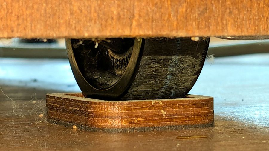
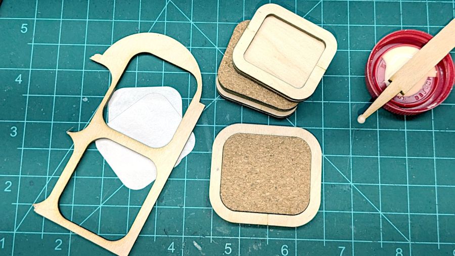
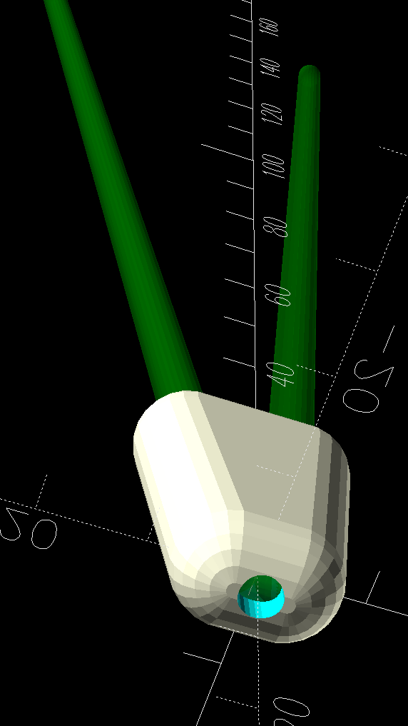
A laser cutter makes close-fitting rings and hot-melt glue sticks those plates together with gleeful abandon:
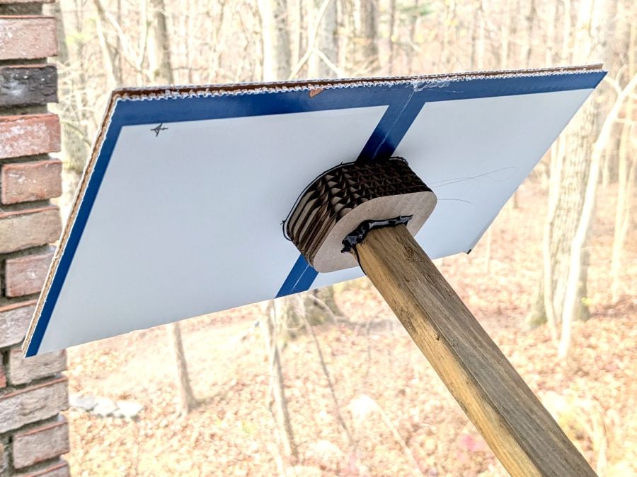
The blue-and-white cardboard plate consists of two box flaps glued together, the glued-up stack of half a dozen rings transfers the torque from the plate to the pole, and the whole affair took the better part of fifteen minutes from idea to cool-enough glue.
It’s back on the garage joists for next year, unless we decide that pole has a higher purpose in life. Worst case, it loses two inches of length.
Bonus: Chore accomplished before the predicted weekend snowfall!