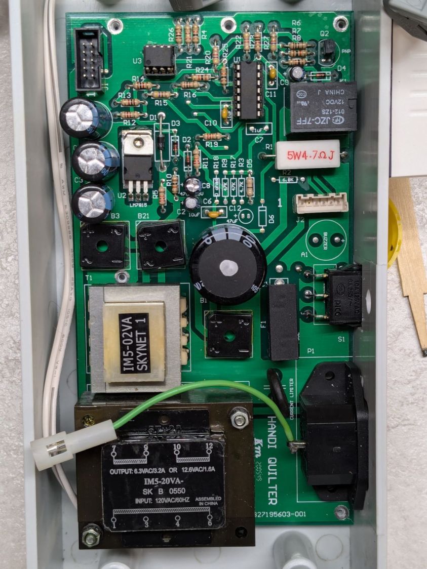
Because I must eventually diagnose and fix the HQ Sixteen’s Motor Stall Heisenbug, I printed out several views of the power supply PCB on glossy photo paper for best visibility.
The component side:
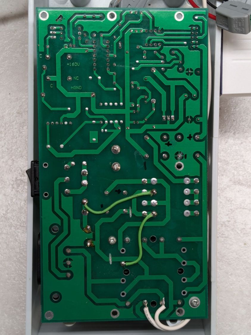
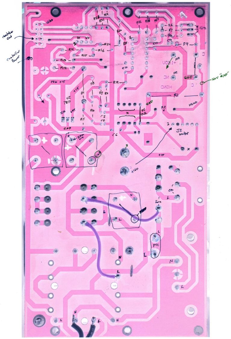
The solder side:
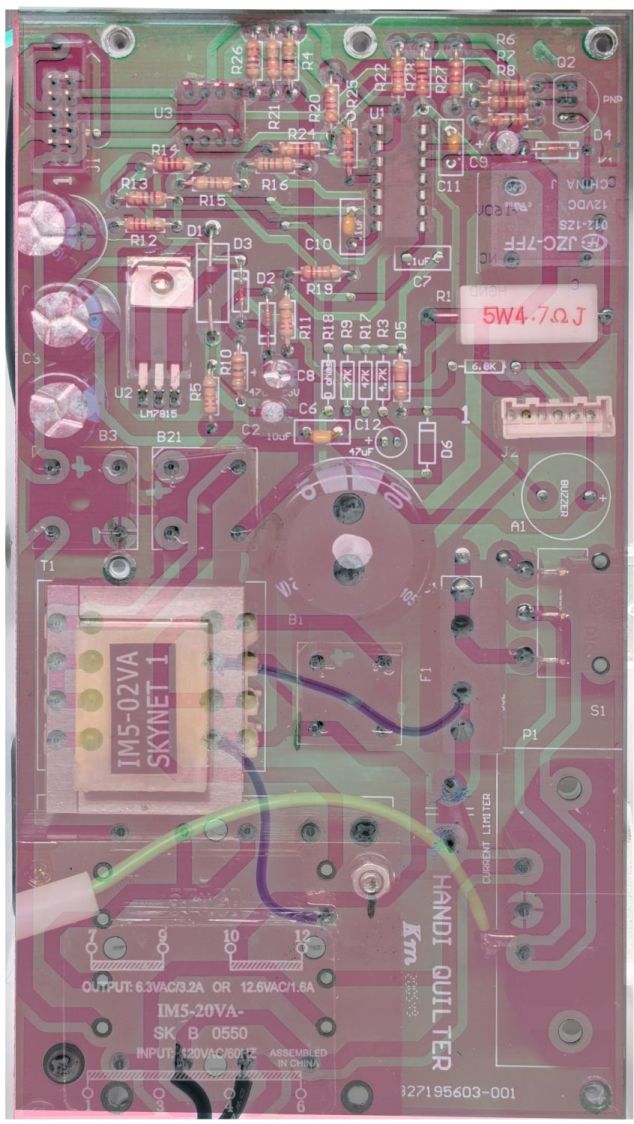
The X-ray view:
Considerable pondering and sketching produced an annotated view of the solder side:
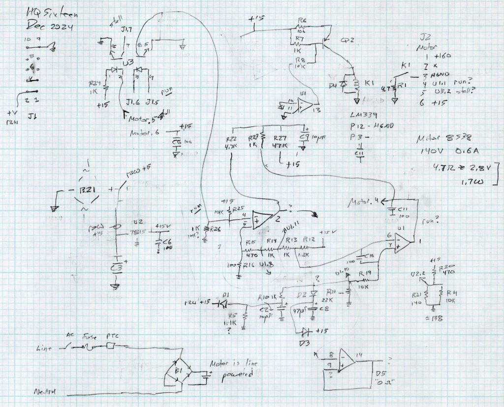
Here’s a tentative schematic drawn on the fly while extracting it from the PCB traces:

!!CAUTION!! I have not verified the schematic against the actual hardware / PCB / components, as the Heisenbug has not reoccurred and I had no occasion to take the machine apart for checking. Do not assume any connections or components are correctly drawn.
Before I redraw the schematic in a more useful format, I must verify several nodes, because not everything in there makes sense.
In particular, the elaborate resistor string in the middle of the page seems to establish reference voltages for everything else, from the motor power supply turn-on delay to the RUN signal starting the motor.
The optoisolators definitely get the RUN command signal from the controller and feed the STALL motor status back to it. That’s assuming I understand enough to pin those labels on those connections.
!!CAUTION!! Read my caveats about the direct-from-the-AC-line non-isolated +160 VDC motor supply before connecting your instruments. The GND traces are not isolated from the AC line and are not at the normal “0 V” AC neutral potential.
But if this mess gets you further along with whatever you were doing, let me know how it all worked out for you.


