Ed Nisley's Blog: Shop notes, electronics, firmware, machinery, 3D printing, laser cuttery, and curiosities. Contents: 100% human thinking, 0% AI slop.
Herewith, the MHVLUG – 3D Printing Status 2104 slides (remember slides?) I’ll be using for my talk this evening at the MHVLUG meeting; you don’t get the audio track in the PDF, but the pictures may be informative.
If you believe everything you read, you might think personal 3D printing will go like this:
3D Printing 2014 – What They Say
But it requires entirely too much of this:
3D Printing 2014 – What They Dont Say
Personal 3D printing requires that you take full control:
3D Printing 2014 – Personal 3D Printing
Not knowing the answers, I’ll still make some guesses about what lies ahead:
3D Printing 2014 – The Future
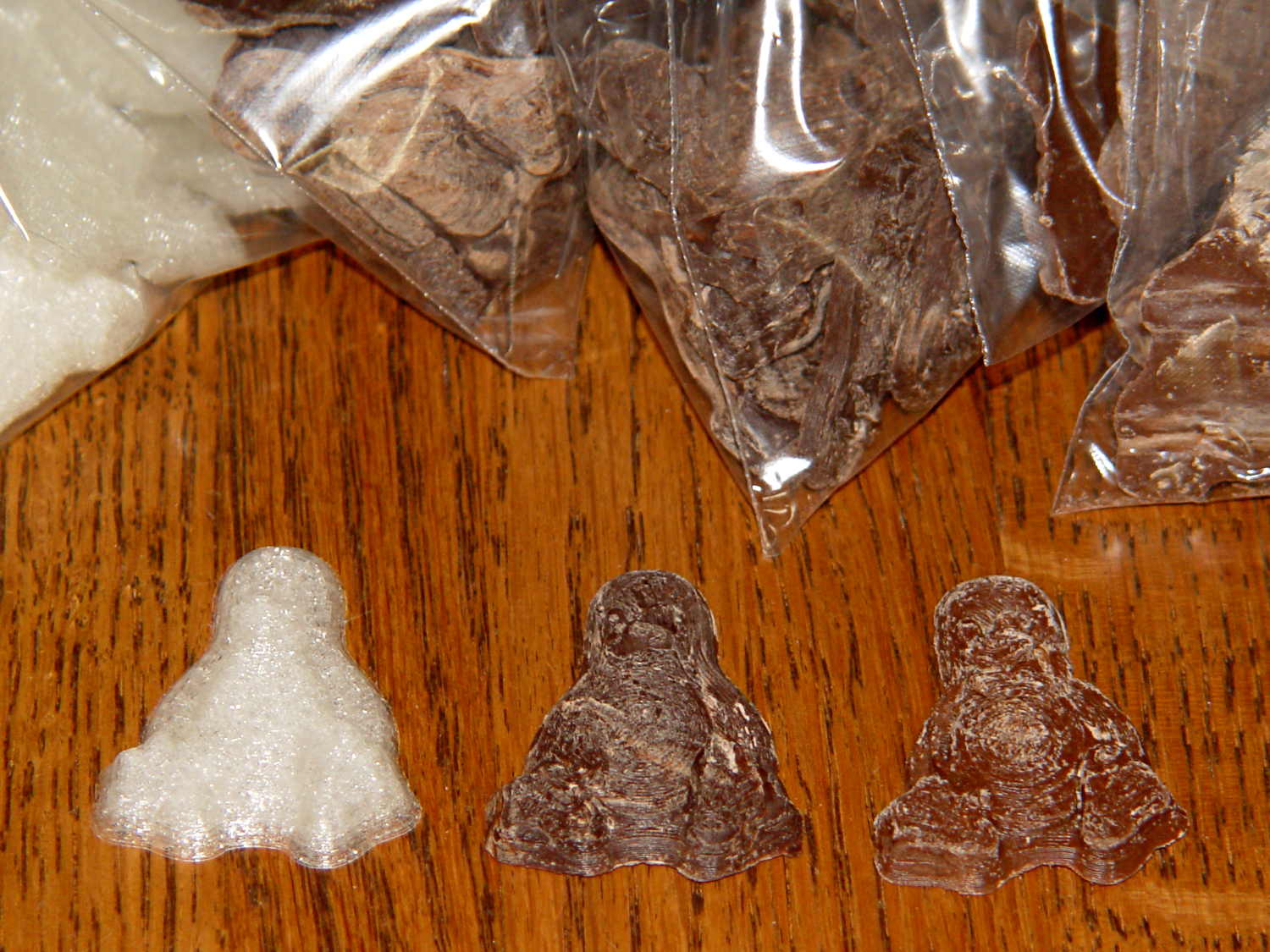
And I found the best tchotchkes ever:
3D Printing 2014 – Tchotchkes
See you there…
(The PDF has clickable links for those images, plus the 60-some-odd other slides. The plan: talk like an auctioneer for an hour!)
Seeing as how the Tux chocolates were produced in a facility containing a big nut, some folks may prefer an (inedible, at least by humans, but correspondingly more permanent) Tux tchotchke in PLA. I plan to have the M2 running off more of them, so there should be enough to go around.
For what it’s worth, you can actually buy a 3D chocolate printer that seems rather overpriced for what’s basically a desktop CNC gantry mill with a heated syringe. The site seems dead, so maybe other folks came to that conclusion, too.
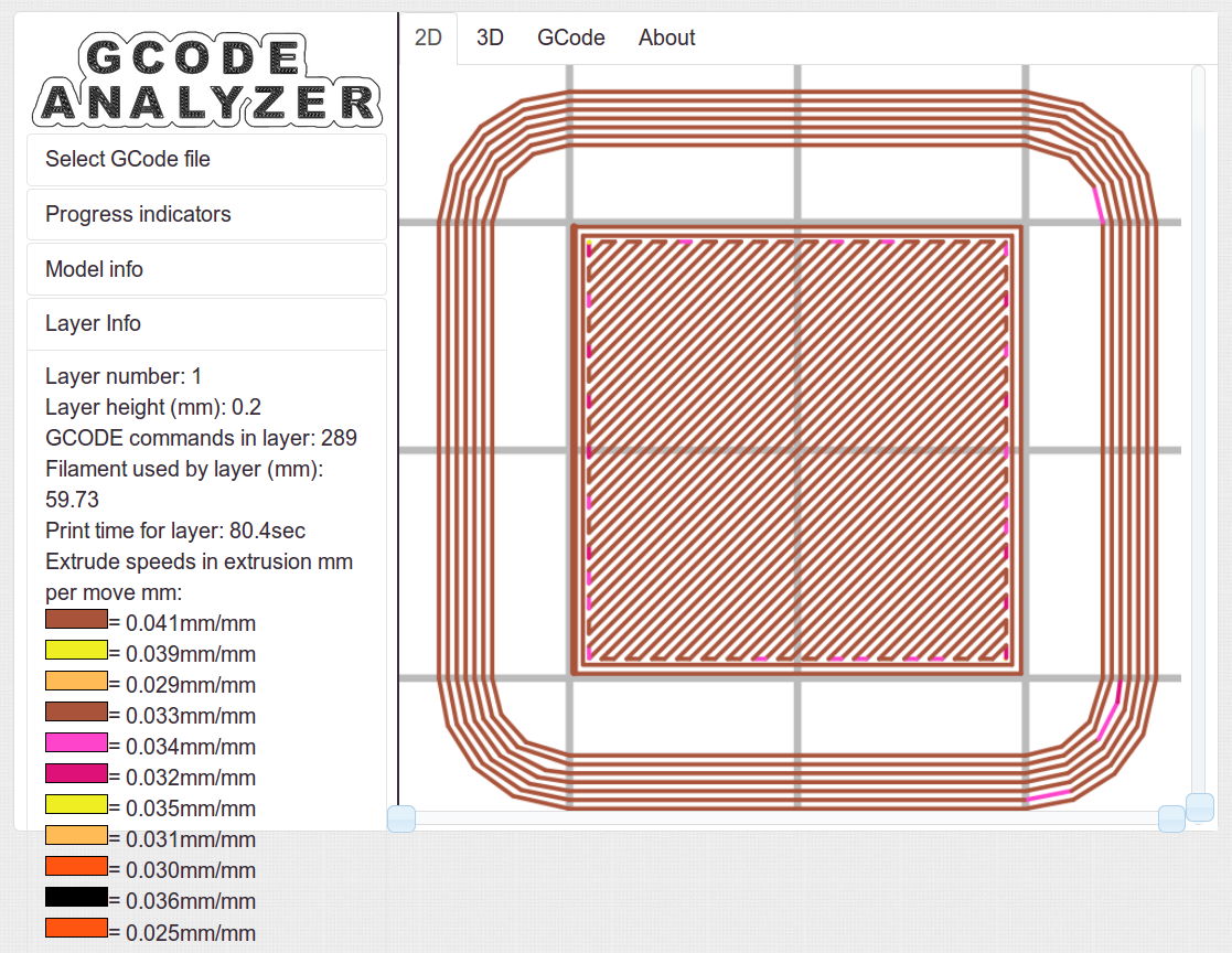
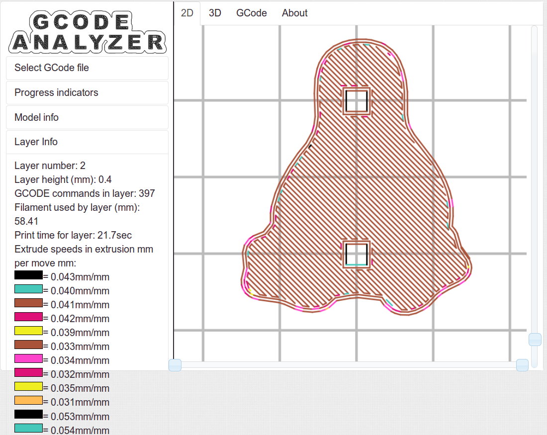
Some pix that serve as a stick in the ground showing that my current Slic3r configuration constellation doesn’t produce thin infill…
All of the layers in the 20 mm calibration cube look just like this:
Solid cube – Slic3r normal infill
The bottom layer of the Tux mold comes out solid:
Tux thread fill – bottom
As does the top:
Tux thread fill – top
The Gcode Analyzeralgorithm that assigns colors to numeric values tends to produce many aliases, although most of the time you can figure out what’s going on. If somebody wants to dive into the code, I’d like to have unique colors and get the color table sorted in ascending order.
The current Slic3r configuration:
# generated by Slic3r 1.1.1 on Sat May  3 10:31:36 2014
avoid_crossing_perimeters = 0
bed_size = 190,250
bed_temperature = 70
bottom_solid_layers = 3
bridge_acceleration = 0
bridge_fan_speed = 100
bridge_flow_ratio = 1
bridge_speed = 150
brim_width = 0
complete_objects = 0
cooling = 1
default_acceleration = 0
disable_fan_first_layers = 1
duplicate_distance = 6
end_gcode = ;-- Slic3r End G-Code for M2 starts --\n;  Ed Nisley KE4NZU - 15 November 2013\nM104 S0		; drop extruder temperature\nM140 S0		; drop bed temperature\nM106 S0		; bed fan off\nG1 Z180 F2000	; lower bed\nG1 X130 Y125 F30000	; nozzle to right, bed front\nM84     	; disable motors\n;-- Slic3r End G-Code ends --
external_perimeter_speed = 25
external_perimeters_first = 0
extra_perimeters = 1
extruder_clearance_height = 25
extruder_clearance_radius = 15
extruder_offset = 0x0
extrusion_axis = E
extrusion_multiplier = 1.07
extrusion_width = 0.4
fan_always_on = 0
fan_below_layer_time = 30
filament_diameter = 1.79
fill_angle = 45
fill_density = 100%
fill_pattern = rectilinear
first_layer_acceleration = 0
first_layer_bed_temperature = 70
first_layer_extrusion_width = 0.4
first_layer_height = 100%
first_layer_speed = 25
first_layer_temperature = 175
g0 = 0
gap_fill_speed = 50
gcode_arcs = 0
gcode_comments = 0
gcode_flavor = reprap
infill_acceleration = 0
infill_every_layers = 3
infill_extruder = 1
infill_extrusion_width = 0
infill_first = 1
infill_only_where_needed = 0
infill_speed = 150
interface_shells = 0
layer_gcode =
layer_height = 0.2
max_fan_speed = 100
min_fan_speed = 75
min_print_speed = 4
min_skirt_length = 15
notes =
nozzle_diameter = 0.35
only_retract_when_crossing_perimeters = 1
ooze_prevention = 0
output_filename_format = [input_filename_base].gcode
overhangs = 1
perimeter_acceleration = 0
perimeter_extruder = 1
perimeter_extrusion_width = 0.4
perimeter_speed = 150
perimeters = 2
post_process =
print_center = 0,0
raft_layers = 0
randomize_start = 1
resolution = 0.05
retract_before_travel = 1
retract_layer_change = 0
retract_length = 1
retract_length_toolchange = 5
retract_lift = 0
retract_restart_extra = 0
retract_restart_extra_toolchange = 0
retract_speed = 60
skirt_distance = 3
skirt_height = 1
skirts = 3
slowdown_below_layer_time = 20
small_perimeter_speed = 25
solid_fill_pattern = rectilinear
solid_infill_below_area = 5
solid_infill_every_layers = 0
solid_infill_extrusion_width = 0
solid_infill_speed = 150
spiral_vase = 0
standby_temperature_delta = -5
start_gcode = ;-- Slic3r Start G-Code for M2 starts --\n;  Ed Nisley KE4NZU - 15 Nov 2013\n;  28 Feb 2014 - 6 Mar 2014 - tweak Z offset\n; Z-min switch at platform, must move nozzle to X=130 to clear\nM140 S[first_layer_bed_temperature]	; start bed heating\nG90				; absolute coordinates\nG21				; millimeters\nM83				; relative extrusion distance\nG92 Z0			; set Z to zero, wherever it might be now\nG1 Z10 F1000	; move platform downward to clear nozzle; may crash at bottom\nG28 Y0			; home Y to be sure of clearing probe point\nG92 Y-127 		; set origin so 0 = center of plate\nG28 X0			; home X\nG92 X-95		; set origin so 0 = center of plate\nG1 X130 Y0 F30000	; move off platform to right side, center Y\nG28 Z0			; home Z with switch near center of platform\nG92 Z-4.40		; set origin to measured z offset\nG0 Z2.0			; get air under switch\nG0 Y-127 F10000	; set up for priming, zig around corner\nG0 X0			;  center X\nM109 S[first_layer_temperature]	; set extruder temperature and wait\nM190 S[first_layer_bed_temperature]	; wait for bed to finish heating\nG1 Z0.0 F500	; put extruder near plate \nG1 E25 F300		; prime to get pressure, generate blob\nG1 Z5 F2000		; rise above blob\nG1 X15 Y-125 F20000	; jerk away from blob, move over surface\nG1 Z0.0 F1000	; dab nozzle to attach outer snot to platform\nG4 P1			; pause to attach\nG1 X35 F500		; slowly smear snot to clear nozzle\nG1 Z1.0 F2000	; clear bed for travel\n;-- Slic3r Start G-Code ends --
start_perimeters_at_concave_points = 1
start_perimeters_at_non_overhang = 1
support_material = 0
support_material_angle = 0
support_material_enforce_layers = 0
support_material_extruder = 1
support_material_extrusion_width = 0
support_material_interface_extruder = 1
support_material_interface_layers = 0
support_material_interface_spacing = 0
support_material_pattern = honeycomb
support_material_spacing = 2.5
support_material_speed = 150
support_material_threshold = 0
temperature = 175
thin_walls = 1
threads = 2
toolchange_gcode =
top_infill_extrusion_width = 0.4
top_solid_infill_speed = 25
top_solid_layers = 3
travel_speed = 250
use_firmware_retraction = 0
use_relative_e_distances = 0
vibration_limit = 0
wipe = 0
z_offset = 0
Over the decades, the same local repair shop has performed the annual NYS inspection on our cars; we started there when it was conveniently near to jobs at the IBM plant and continued out of habit. In the last, oh, five years or so, they’ve begun reporting all manner of Things That Need Work, ranging from “dirty fluids” to worn shocks. Oddly, none of those problems recurred from year to year and were never written up on the inspection summary; they were always phoned to Mary, who politely declined the service.
On several occasions, I’d drop off the car and walk to the mall across the road to pick up this-and-that. They’d call Mary (I don’t carry the phone), she’d say she would pass the message to me, and they would never mention the problems when I picked up the car. Huh.
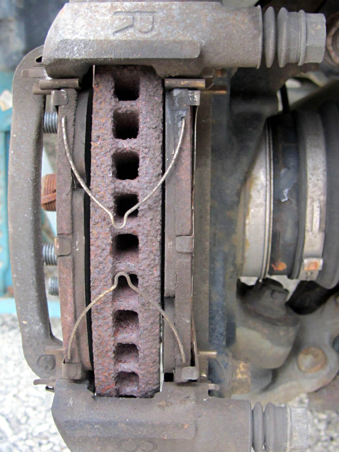
Most recently, they told her the front brakes had “wafer thin” pads and the rotor disks were severely worn. She declined the service, as always. When I change the oil, I do an under-the-car lookaround and the brakes have always looked fine, but, being that type of guy, I pulled the front wheels and took a closer look at the situation:
Right Front Brake
The pads start at 7 mm and wear to a minimum thickness of 1 mm, at which point the cross-pad wear indicating groove will vanish and a little metal tab will touch the rotor and start screaming. These pads have about 2 mm left to the bottom of the grooves and are wearing evenly.
The rotors start at 28 mm thick and wear to 26 mm. These rotors measure 27.73 mm and have no serious grooves or scars.
Just for grins, I pulled the rotors and measured the thickness at the middle of the swept ring, aligned with the bolt holes:
Sienna rotor thickness
Bottom line: the rotors match to within 0.0015 inch = 0.04 mm and have 0.0005 inch = 0.013 mm of variation around the circumference.
With 91 k miles on the OEM pads and rotors, I’d say they’re doing fine and that we don’t use the brakes nearly enough.
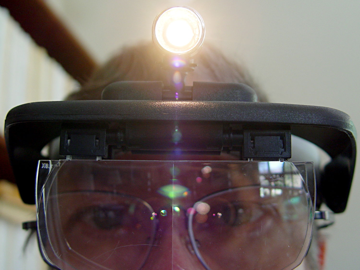
One of my headband magnifiers has a headlight above the brim, an incandescent flashlight bulb powered by a pair of AAA alkaline cells, that hasn’t worked well since the day I bought it. This being a time of finishing small projects, I finally tore it apart and discovered that the cells and contacts were in fine shape (!), the bulb (remember bulbs?) worked, the wiring was OK, but the switch was bad.
Magnifying headband – lamp switch
The switch body seems to be firmly anchored in place, so I pried that red base plate off in situ, un-bent the silver-plated (!) spring-contact-actuator, and reassembled it in reverse order. No pictures, as it took less time to do than to tell, but it now works perfectly… most likely, for the first time ever.
Stop squirming! This can be much more painful…
Magnifying headband – in action
I’m mildly tempted to hotwire the guts of a white LED flashlight into the thing, but that would require either another AA cell or a booster circuit and I’m not ready for that just yet.
My original dimensions for the helmet mirror mount used three sections of the inspection mirror shaft, with a short length of the fattest tube screwed into the azimuth turret:
Mirror shaft – 2-56 stud
Each section has a pair of brass leaf springs applying just enough friction to hold the next-smallest tube in place, with a rolled crimp securing the springs and preventing the smaller section from pulling out. My first version used that short length of the largest section and the next (for Mary’s helmet) used only the two smallest tubes; it’s rapid prototyping at its finest, except that I rarely discard a prototype that actually works.
Late last year I managed to pull the shaft out of the base while adjusting the length and watched those two springs flutter to the ground beside me.
After finding both of them amid the usual roadside clutter, I swore a mighty oath that I’d epoxy the base of the middle tube into the larger one, eliminating one non-functional adjustment point:
Bike helmet mirror mount – epoxied stalk base
The heatstink tubing covers most of the evidence, but you can see a fillet of epoxy around the end.