The Smell of Molten Projects in the Morning

Ed Nisley's Blog: Shop notes, electronics, firmware, machinery, 3D printing, laser cuttery, and curiosities. Contents: 100% human thinking, 0% AI slop.

Category: Machine Shop

Mechanical widgetry

  • Slicing Anomaly: Thin Fill

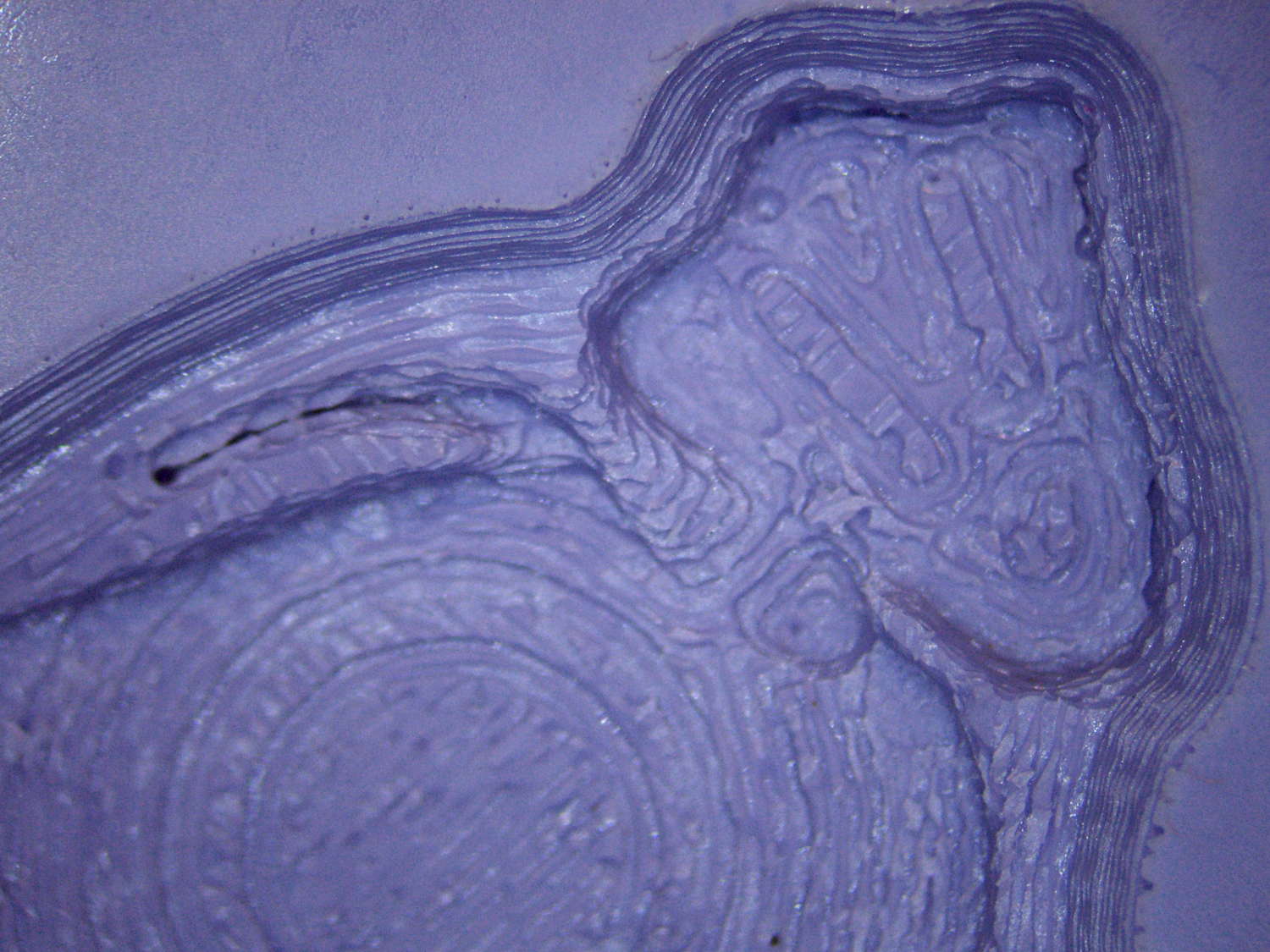
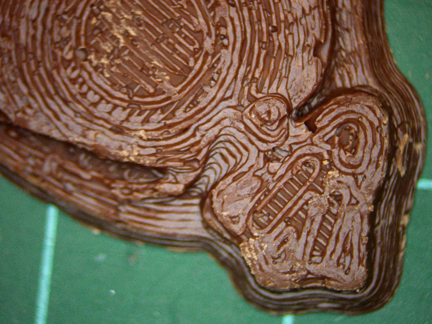
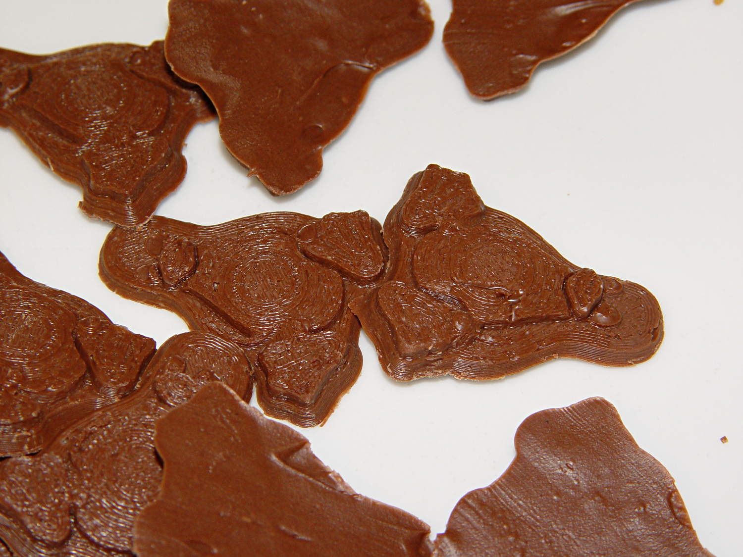
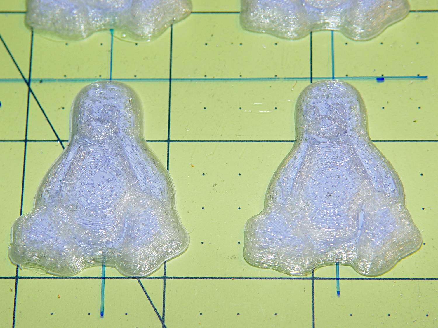
    Having discovering that the chocolate mold positives suffered from sparse top infill, to the extent that silicone rubber would flow right though the surface…

    Tux Gradient - PLA positive detail
    Tux Gradient – PLA positive detail

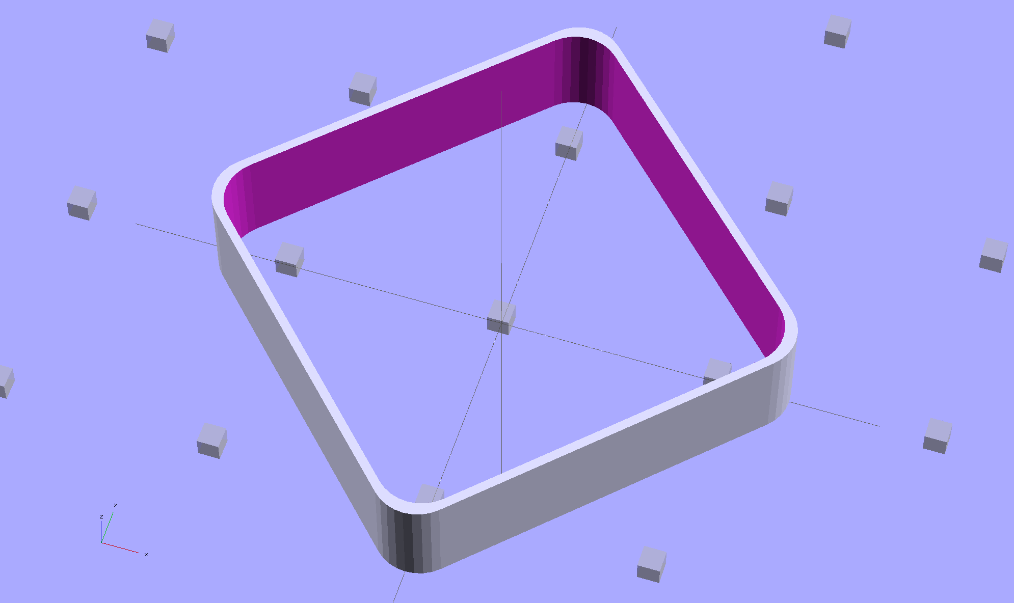
    … I ran off a few variations of the classic 20 mm calibration “cube” (which is 10 mm tall):

    Solid cube - thin top infill - on platform
    Solid cube – thin top infill – on platform

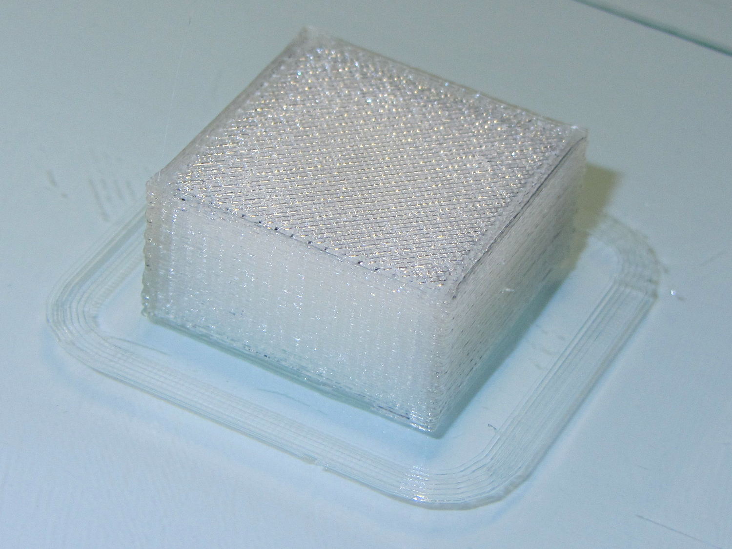
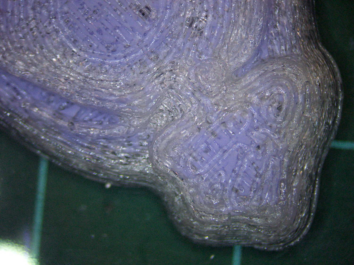
    Not only were the infilled surfaces porous, I could see right through the block! That’s impossible to photograph, but here’s a laser beam shining through the entire 10 mm stack, showing how precisely the M2 aligns 50 under-filled thread layers:

    Solid cube - laser transmission
    Solid cube – laser transmission

    The yellow spot in the middle marks the overexposed laser beam. There’s a distinct beam passing through the block that, with the proper orientation, can create a spot on the cutting mat atop my desk.

    In fact, I can blow air through the blocks; one could use them as (rather coarse) air filters.

    Normally, underfill happens when a mechanical problem prevents the printer from feeding enough filament to keep up with demand, but that’s not the case here: the perimeter threads came out exactly 0.4 mm wide for the entire height of the cube, as you can see if you click the picture for more dots. The top and bottom infill, plus all the interior threads, seem to be about half the nominal width and don’t touch their neighbors on the same XY plane at all.

    Alex Ustyantsev’s incomparable G-Code Analyzer shows that Slic3r baked the problem right into the G-Code, so the M2 is cranking out exactly the right amount of filament:

    Solid cube - Slic3r thin infill
    Solid cube – Slic3r thin infill

    The colors show the length of extruder filament per millimeter of XY motion, not the usual XY speed, with the two perimeter threads at 0.033 mm/mm and the interior at 0.18 mm/mm. In round numbers, the G-Code starves the infill by a factor of 1.8, which is close enough to the factor of two I’d guessed going into this mess.

    Being that type of guy, I set the exact extrusion thickness and width (0.20 x 0.40 mm), rather than let Slic3r pick them. The extruded thread has a fixed cross-section of (roughly) 0.080 mm2 and a millimeter of XY motion thus requires 0.080 mm3 of filament.

    The PLA filament measures 1.79 mm diameter, for a cross-section of 2.5 mm2. Getting 0.080 mm3 from the incoming filament requires feeding 0.032 mm into the extruder, which is almost exactly what you see for the perimeter threads.

    After restoring Slic3r’s default configuration, the problem Went Away, which suggests that I backed the algorithms into a corner with some perverse combination of settings. Rebuilding my usual configuration from the defaults also worked fine, so it’s obviously not Slic3r’s problem.

    Which one is not like the other ones?

    Solid cube tests
    Solid cube tests

    You can see the thin infill on three of those cubes, with the solid one in the lower right showing how it should look.

    The solid cube weighs 4.4 g and the thin-fill variations weigh 2.7 to 2.9 g. Assuming PLA density = 1.25 g/cm3 and “cube” volume = 4 cm3, a completely solid cube should weigh 5.0 g. I think 4.4 g is close enough; the top surface came out flat with nice adjacent-thread fusion. Working backwards, the average fill = 88%; the perimeter is fused-glass solid, so the actual infill will be a bit under that.

    I generally run Slic3r from my desktop box, with ~/.Slic3r symlinked to the actual config directory and its files on the NFS server downstairs. Perhaps running different versions of Slic3r on two or three different boxes, all using the same config files, wrecked something that didn’t show up in the UI and produced bad slices. I probably ran two different versions of Slic3r at the same time against the same files, although I wasn’t simultaneously typing at both keyboards.

    Moral of the story: check the G-Code before assuming a hardware failure!

  • Revised Thinwall Open Box Calibration Object

    Which thinwall open box is better?

    Object A:

    Thinwall Open Box - Minkowski - solid model
    Thinwall Open Box – Minkowski – solid model

    or Object B:

    Thinwall Open Box - hull - solid model
    Thinwall Open Box – hull – solid model

    The latter, of course: I blundered the inner corner radius, which occasionally produced little tiny dots of infill that shouldn’t be there. Just one of those errors that hides in plain sight until something else goes wrong, then it’s obvious.

    Rather than fix the Minkowski version, I rebuilt it using the hull() operator to shrinkwrap four cylinders for each solid, then remove the smaller block from the larger. Commenting out the hull() operators  shows that the cylinders now line up properly:

    Thinwall Open Box - un-hulled - solid model
    Thinwall Open Box – un-hulled – solid model

    The OpenSCAD source code:

    // Thin wall open box calibration piece
    // Adapted from Coasterman's Calibration set
    // Ed Nisley - KE4ZNU - Dec 2011
    // Adjust for Slic3r/M2 - March 2013
    // Reworked for hull() with correct corner radii - April 2014
    
    //-------
    //- Extrusion parameters must match reality!
    //  None of the fill parameters matter
    
    ThreadThick = 0.20;
    ThreadWidth = 0.40;
    
    Protrusion = 0.1;           // make holes end cleanly
    
    function IntegerMultiple(Size,Unit) = Unit * ceil(Size / Unit);
    
    //-------
    // Dimensions
    
    Height = IntegerMultiple(5.0,ThreadThick);
    
    WallThick = ThreadWidth;
    
    CornerRadius = 2.0;
    CornerSides = 4*8;
    
    SideLen = 20.0 - 2*CornerRadius;
    
    Rotation = 45;
    
    //-------
    
    module ShowPegGrid(Space = 10.0,Size = 1.0) {
    
      Range = floor(50 / Space);
    
        for (x=[-Range:Range])
          for (y=[-Range:Range])
            translate([x*Space,y*Space,Size/2])
              %cube(Size,center=true);
    }
    
    //-------
    
    ShowPegGrid();
    
    rotate(Rotation)
    	difference() {
    		hull() {
    			for (i=[-1,1], j=[-1,1])
    				translate([i*SideLen/2,j*SideLen/2,0])
    					cylinder(r=CornerRadius,h=Height,$fn=CornerSides);
    		}
    		hull() {
    			for (i=[-1,1], j=[-1,1])
    				translate([i*SideLen/2,j*SideLen/2,-Protrusion])
    					cylinder(r=(CornerRadius - WallThick),h=(Height + 2*Protrusion),$fn=CornerSides);
    		}
    	}
    
  • Replacing Phil Wood Hub Bearings

    Back in 2001, I specified Phil Wood hubs for our then-new Tour Easy recumbents, as I had absolutely no interest in fiddling with wheel bearings; been there, done that, it’s no fun at all.

    Fast forward thirteen years, during which time I’ve done zero hub maintenance.

    A few weeks ago, while backing my ‘bent out of the garage, the front wheel stopped rolling and skidded on the asphalt. Usually, that means a brake problem or something wedged between the wheel and the fender, but in this case, the axle itself jammed: the front bearings seized. I eased a bit of penetrating oil under the seals, the bearings began turning, and we continued the ride as planned.

    A close look at the hub shows that, back in the day, Phil Wood used personalized bearings, made in Switzerland by WIB:

    Phil Wood Front Bearing - view 2
    Phil Wood Front Bearing – view 2

    Phil Wood is still in business and a brief email exchange produced the proper bearing number: PWX92, at $17 each. I bought a pair to show my support. It turns out that the new bearings are from NSK and aren’t personalized.

    The listing shows that the generic part number is 6902 and gives the dimensions:

    • OD = 28 mm
    • ID = 15 mm
    • Width = 7 mm

    I bought a lot of 10 6902RS2 deep-groove bearings from VXB for $35.90 delivered, so that I can compare their performance with The Real Thing.

    Use a pair of 5 mm hex wrenches to remove one of the end caps, then gently tap the aluminum axle out of the hub:

    Phil Wood front axle and bearing
    Phil Wood front axle and bearing

    The grease inside looks as good as the day they installed it: no water leaked through the seals or past the races.

    Having a lathe ready to hand, I grabbed the axle in the chuck and unscrewed the other cap:

    Phil Wood front axle - in lathe chuck
    Phil Wood front axle – in lathe chuck

    Everything came apart easily!

    I applied grease everywhere, slid a new bearing and its wave washer into place on the axle, aligned it with the hub bore, and pushed it halfway into place.

    Rather than beat on the bearings, I conjured a simple adapter that let me use the quick-release skewer as a press to persuade the outer race into the hub recess:

    Phil Wood front axle - improvised press
    Phil Wood front axle – improvised press

    I stacked an old bearing between the skewer nut and the new bearing on the other side, with a fender washer to distribute the pressure on the old bearing. In general, you don’t want to press the bearings into place by applying pressure to the inner race, but in this case the pressure was so low that it probably didn’t matter.

    With one bearing in place, remove the press, slide the second wave washer & bearing on the other end of the axle, install the press, push the bearing into place, tighten the end caps, and … it’s done!

    Flushed with success, I repeated the operation on the front wheel of Mary’s bike. Those bearings felt better, but they turned with essentially no friction at all. That’s a sign the internal grease was pretty much gone and failure loomed over the horizon.

    Cutting the seals out of the worst bearing from my bike showed water had gotten into the assembly:

    Phil Wood axle bearing - interior
    Phil Wood axle bearing – interior

    This is not how a bearing should look:

    Phil Wood axle bearing - disassembled
    Phil Wood axle bearing – disassembled

    The other bearing looked (and felt!) much better, but you always replace ’em in pairs.

    Mary’s bike now has the new Phil Wood / NSK bearings, mine has the VXB bearings, and we’ll see what transpires. Both bikes sound much quieter, mine in particular, and I’m sure they roll better…

    The rear tire on my bike needs replacing early this season, at which point I’ll dismantle the sprocket and install another two VXB bearings.


  • Monthly Image: Expedient Water Tank Repair

    If the only tool you have is a wooden plug…

    Wood-plugged water tank - tweaked
    Wood-plugged water tank – tweaked

    I took that picture back in mid-1969, near the Hummelstown, PA water treatment and pumping plant.

    The overhead view now shows a small tank behind the water plant, with that house just across the access road at the bottom of the image:

    Hummelstown PA water plant - overhead - ca 2013
    Hummelstown PA water plant – overhead – ca 2013

    Judging from the perspective and the row of bushes, the old tank probably stood across the (now abandoned) tailrace, near that little dot in the mowed area. The dam (in the lower right corner) washed away during a flood some decades ago; I have no idea where Hummelstown gets its water.

    That once-spiffy limestone house, built with stone from a local quarry, has fallen on hard times:

    Hummelstown PA water plant - ca 2013
    Hummelstown PA water plant – ca 2013

    The pump house features Hummelstown Brownstone, which also appears in the finest old buildings all along the East Coast. If you poke around the area, you’ll find traces of the Hummelstown Brownstone Company, including several of their quarries. If I recall the story correctly, my father was Mr. Walton’s chauffeur.

    The other house may have vanished when the Graystone Farms development ate the surrounding area. Unlike most housing development names, where the name indicates something obliterated to make way for the houses, that area still has plenty of gray limestone:

    Hummelstown PA water plant - Pennsy Supply Quarry - ca 2013
    Hummelstown PA water plant – Pennsy Supply Quarry – ca 2013

    That’s an active limestone quarry, even if they’re not excavating the main pit these days. The orange marker in the lower left marks the water plant; Graystone Farms in the corner. Yeah, that’s a big pit.

    I digitized my slide collection somewhere around the turn of the current millennium. This slide faded to a distinct magenta tint that I’ve removed with crude color correction, plenty of dust mars the image, and so forth and so on, but I (still) sympathize with that poor guy faced with a daunting task.

    Imagine a kid with a camera poking around an active water treatment station in this day and age…

  • Chocolate Molds: Closeups

    An overall view of the mold:

    Tux Gradient 4x4 - mold separated
    Tux Gradient 4×4 – mold separated

    The PLA positive, after removing the silicone negative, showing the silicone below the surface:

    Tux Gradient - PLA positive detail
    Tux Gradient – PLA positive detail

    The corresponding silicone negative cavity, flipped top-to-bottom:

    Tux Gradient - silicone negative detail
    Tux Gradient – silicone negative detail

    The milk chocolate result, although probably not from the same cavity:

    Tux Gradient - milk chocolate detail
    Tux Gradient – milk chocolate detail

    The radial gradient on the tummy comes through clearly and, I think, pleasingly, even though it’s only a few layers tall. The threads defining the flipper just above (to the left, in these images) of the foot show where the flipper crosses the tummy and foot level. I didn’t expect the foot webbing grooves to get that ladder-like texture, but I suppose having non-slip foot treads would be an advantage.

    If you don’t mind the hand-knitted texture, which I don’t, this process seems perfectly workable.

  • Chocolate Molds: Tempering and Pouring

    Having experimentally determined that tempering molten chocolate is not optional (i.e., chocolate doesn’t behave just like butter), I tried a cheat discussed in the comments following that helpful post. Basically, because all retail chocolate is already tempered, you can get good results by carefully heating it to the proper temperature, then pouring it into the molds… the proper crystals remain in their places, the cooled chocolate has good snap, and you avoid a huge amount of fuffing and fawing.

    Not having a sous vide setup, but also not working with giant chocolate blocks, I simply filled a big ceramic pot with tepid water:

    Chocolate tempering - water bath
    Chocolate tempering – water bath

    Note that the gas burner under the pot is off: the pot’s on the stove because it fit nicely next to the countertop.

    A small metal pot sits out of sight on the burner to the left. Goosed with low heat as needed, that pot provided warm water: I moved a cup of tepid water to the metal pot, moved a cup of slightly warmer water back to the ceramic pot, and repeated as needed. As it turned out, the big pot held its heat quite well and the whole process went swimmingly, with the water temperature at 90±1°F, tops.

    The Official Tempering Numbers seem to be:

    • Dark chocolate: 88 – 90°F
    • Milk chocolate: 86 – 88°F

    I suppose I should have used slightly cooler water for the milk chocolate shown in the picture, but it came out Just Fine.

    I used Nestlé Toll House Chocolate Morsels for lack of anything better. As nearly as I can tell, cheaper chocolate isn’t really chocolate and fancier chocolate seemed like a Bad Idea until I’ve made a few more mistakes. One bag each of Milk, Dark, and Semi-Sweet sufficed for my simple needs.

    The ziplock baggie holds 50 g of chocolate chunks / morsels / whatever, which turned out to be exactly the right amount to fill 16 Tux mold cavities with a 5 mm maximum depth, plus a little bit for the inevitable mess. Sometimes, I just get lucky…

    Put chocolate chunks into bag, squeeze out as much air as possible, seal, drop in the pot. Wait a few minutes until it’s not quite completely melted, remove, dry the bag, squeeze out the rest of the air, then knead until it’s all mooshy.

    Then cut off one corner of the bag, squeeze chocolate into mold cavities, and flatten the back. I started by easing it into the beak and eyes, filling the tummy, then piling enough to cover everything else. This worked surprisingly well, although the ziplock can unlock if you squeeze hard enough; cut the corner a little bit larger than seems necessary.

    Memo to Self: tape the ziplock part of the bag closed to prevent bloopers.

    I used a plastic scraper (well, an unused credit card, if you must know) to moosh the chocolate into the cavity and level the back. There doesn’t seem to be much to choose between doing one cavity at a time or a whole row in one pass, although filling more than one row lets the first lump get too cool.

    I worried about the chocolate in the bag getting too cool, until I realized that my fingers are hotter than the tempering bath, so, if anything, it would get too hot.

    The result came out surprisingly tidy:

    Tux Gradient 4x4 - milk chocolate in mold
    Tux Gradient 4×4 – milk chocolate in mold

    The silicone block sits atop an aluminum pizza pan, which I transported to the basement for cooling while filling and melting the next bag; the chocolate popped right out of the cavities at about 70°F.

    The result looked pretty good to me:

    Tux Gradient 4x4 - milk chocolate detail
    Tux Gradient 4×4 – milk chocolate detail

    The detail come out fine and if anybody kvetches about a few bubbles, they don’t get any more.

    From left to right, Tux in milk, semi-sweet, and dark chocolate:

    Tux Gradient - milk semi-sweet dark lineup
    Tux Gradient – milk semi-sweet dark lineup

    The semi-sweet Tuxes began to bloom almost instantly. I had heated the silicone mold to about 90°F in an attempt to keep the chocolate melty enough to fill 16 cavities before leveling them all at once, but I think it was too hot on the bottom; the four center pieces bloomed right out of the mold and a few others bloomed shortly thereafter.

    The bloom highlights the mold detail, though:

    Tux Gradient - semi-sweet chocolate bloom
    Tux Gradient – semi-sweet chocolate bloom

    I quickly destroyed all the evidence…

    Each Tux weighs 2.5 to 3 g. You do the calorie count yourself, OK?

  • Chocolate Molds: Acrylic Base

    Although directly printing the 2×2 molds worked reasonably well, that does not scale to larger arrays, because OpenSCAD doesn’t handle the profusion of vertices with any grace. Duplicating the STL file created from the height map image, however, isn’t a problem:

    Tux-Gradient - Slic3r layout
    Tux-Gradient – Slic3r layout

    I actually did it in two passes: 4 molds to be sure they’d come out right, then another dozen. Figure a bit under two hours for the lot of them, no matter how you, ah, slice it.

    A grid drawn directly on 1/16 inch = 1.5 mm acrylic sheet guided the layout:

    Tux Gradient 4x4 - mold as-cast
    Tux Gradient 4×4 – mold as-cast

    I anointed the back of each mold positive with PVC pipe cement, the version with tetrahydrofuran to attack the PLA and acetone/MEK to attack the acrylic, lined it up, and pressed it in place. The positives have recesses for alignment pins, but even I think that’s overkill in this application.

    Memo to Self: Flip the acrylic over before gluing, so the guide lines wipe neatly off the bottom.

    Tape a cardboard frame around the acrylic, mix & pour the silicone, put it on the floor to ensure it’s level (unlike our kitchen table), wait overnight for the cure, then peel positive and negative apart:

    Tux Gradient 4x4 - mold separated
    Tux Gradient 4×4 – mold separated

    As before, the top surface of the positives isn’t watertight, so the silicone flowed through into the molds. This isn’t a simple extruder calibration issue, because the thinwall boxes are spot on, all the exterior dimensions are accurate, and everything else seems OK. What’s not OK is that threads on the top and (now that I look at it) bottom surfaces aren’t properly joining.

    A closeup of the positive shows silicone between the threads and under the surface:

    Tux Gradient 4x4 - postive detail
    Tux Gradient 4×4 – postive detail

    But the negative silicone looks just fine, in the usual hand-knitted way of all 3D printed parts:

    Tux Gradient 4x4 - negative detail
    Tux Gradient 4×4 – negative detail

    Definitely fewer bubbles than before, although the flange between the flippers (wings? whatever) and the body isn’t as clean as it could be. Doing better may require pulling a vacuum on the silicone, which would mean the positives really must be air-tight solids.

    Anyhow, the acrylic base produced a wonderfully flat surface that should make it a lot easier to run a scraper across the chocolate to remove the excess. Not that excess chocolate is ever a problem, but it’s the principle of the thing.