Ed Nisley's Blog: Shop notes, electronics, firmware, machinery, 3D printing, laser cuttery, and curiosities. Contents: 100% human thinking, 0% AI slop.
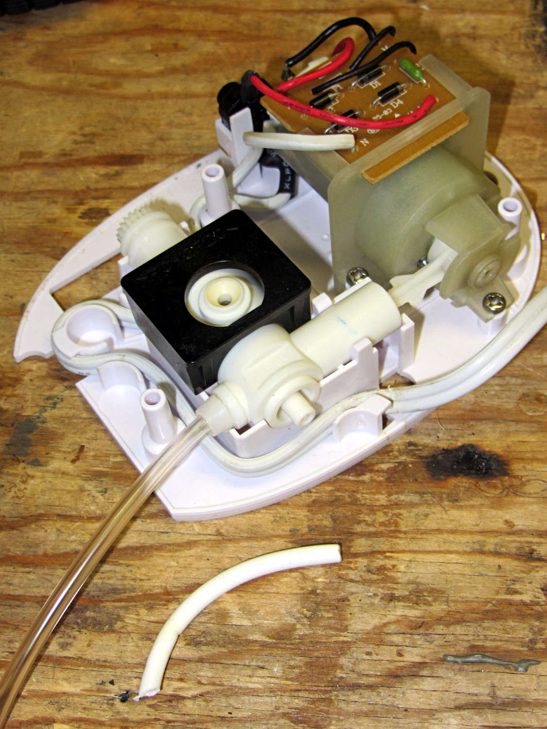
The brittle tubing on Mary’s Interplak water jet continued to disintegrate, so I replaced the entire tube with Tygon:
Interplak water jet – interior
Nisley’s First Rule of Plumbing: Never, ever look inside the pipes delivering water to your faucet.
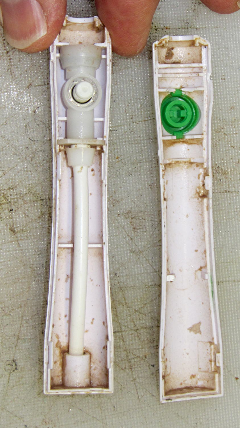
Interplak handle – interior view
That’s not quite inside the pipes, but it’s pretty grotendous, isn’t it?
As expected, flexible tubing doesn’t transmit the pressure pulses nearly as well as the OEM rigid tubing, so we finally bought a new Waterpik. At least you can get replacement tubing for Waterpiks, but I’ll wait until it fails before stocking up.
Contrary to what you might expect, I cut the Interplak’s cord, harvested the motor windings, and dumped the carcass in the trash.
I backed the Forester up to put the rear tires over the edge of the garage apron, which provided enough room to work underneath without jacking the thing; there’s a chock under the left front wheel, never fear.
The instructions from etrailer.com were entirely adequate, so there’s not much point in a detailed writeup. Their time estimate (an hour) seems grossly understated, but I wasn’t in any hurry.
A morning of pleasant wrenching produced a good-looking, albeit nearly invisible, result:
Forester trailer hitch – installed
Both hitches bolt directly to the frame and I have no idea what effect that has on the collision behavior. My guess is that the Subaru hitch would be more bendy, if only because it has a much lower load rating, but that probably doesn’t make much difference.
Some notes:
Remove the muffler, which is trivially easy on a new car, and reuse the crushable gasket, which is probably not recommended. After releasing the muffler, you can ease the mounting pins out of their rubber supports without applying any lube or issuing many curses. The tailpipe remains in place, conveniently away from the proceedings.
As others have noted, remove the heat shield, snip a few square inches from the inside front corner, and reinstall with only three screws. I chopped clearance holes for the hitch bolts using a box cutter, but you could probably just punch them right through the butter-soft aluminum sheet.
The instructions suggest drilling / rasping the center mounting holes to 1-1/8 inch diameter. Being that type of guy, I used a step drill to get a 1 inch hole, filed slots on the front and rear sides to accommodate the reinforcing plates, then filed the corners where the slots meet the hole for the carriage bolt heads. The bolts and plates just barely fit, but that leaves more metal on the frame; I doubt any of that matters.
I felt badly about leaving steel filings inside the frame, but there’s no practical way to extract them. I didn’t prime-and-paint the raw edges, either, as they’re buried deep inside the hitch frame; I may regret that decision.
Wear eye protection: those six fish wires have lethally sharp and very whippy ends.
You can support the hitch on your chest to maneuver it into position, but an assistant must hold it in the proper alignment while you fiddle with fish wires, bolts, and nuts.
I don’t know what happens to the raised bump in the frame under the heat shield, but I suspect it gets crushed flat after torquing the nuts on either side.
When you reinstall the muffler, remember to take the gasket off the mounting pin where you put it for safekeeping before maneuvering the pins back into the hangers …
The Official Subaru OEM Hitch Assembly Instructions commence with loosening the taillight housings and then get complicated. That hitch mounts on a crossbar that completely replaces the bumper beam inside the dress cover, the receiver extends through a small square section of the cover that you cut out as part of the process, the mount occupies the two rearmost holes in the frame members, and it doesn’t require trimming the heat shield. It also costs nigh onto $800 including dealer labor.
Both Shimano SPD pedals on my Tour Easy have been creaking while climbing hills and I’ve gradually eliminated all the usual mechanical suspects: loose bottom bracket bearings (it’s a cartridge), loose cranks (they’re the old-school tapered squares), loose pedal spindles, and so forth. Of course, it’s impossible to produce the creak with the bike clamped in the work stand, which make debugging particularly frustrating.
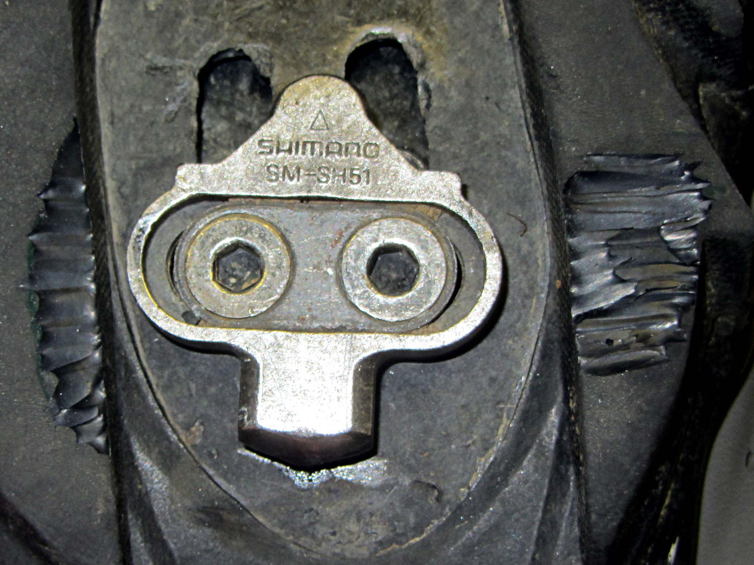
After all that, I noticed the shoe soles were wearing the pedal frames just outside the cleat clamps:
Shimano SPD pedal – shoe sole abrasion
So I went so far as to carve away a bit of the sole:
Shimano SPD cleat – trimmed shoe sole
Turns out none of that solved the problem.
What did solve the problem: a drop of oil on the rear of the cleat. You can see a smear of oil on the sole; it doesn’t take quite so much.
As nearly as I can tell, the rear of the cleat drags on the slightly irregular surface of the clamp and, both surfaces being hardened steel, they stick-and-slip just slightly.
A dab of grease may provide longer-lasting relief …
Eks found some heavy-duty ET227 NPN transistors in his heap and put them on the basement steps for me … months ago, because he knew I’d be needing them.
Mounting an ET227 on a massive CPU heatsink with thermal compound and wiring it in place of the failed MOSFET produces this lashup:
Kenmore 158 – ET227 FW drive
The base drive comes directly from a bench supply and the collector sees full-wave rectified 120 VAC from the isolated Variac. The maximum base current rating of 40 A at DC suggests it’ll be difficult to screw this one up. The rectifier bridge doesn’t dissipate enough power to warm up, even without a heatsink.
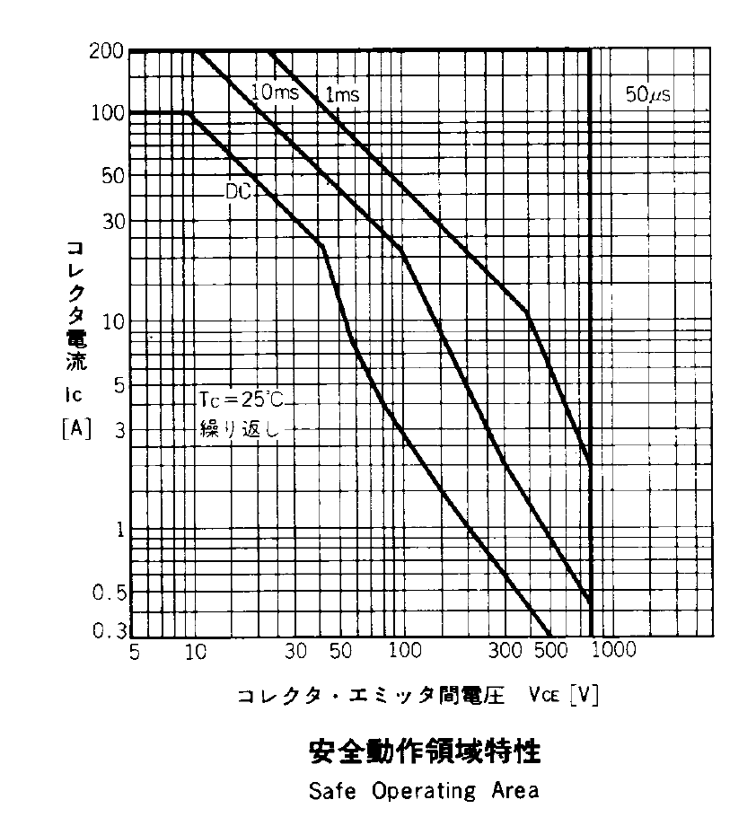
The SOA plot from the ET227 datasheet has the expected 1 kV and 100 A limits that you can’t actually reach under most conditions:
ET227 – Safe Operating Area
The Kenmore 158 motor has a DC resistance of about 50 Ω, so the locked-rotor current won’t be more than about 3 A. The motor current runs around 700 mA with a voltage drop across the transistor ranging from 20 V to 50 V at normal operating conditions, so it’s just barely within the DC SOA. So far, my efforts to kill it by stalling the motor have been unavailing; I have four spares and Eks has at least five more in his heap.
The ET227 has a 960 W (!) maximum dissipation on an ideal heatsink, so the piddly 35 W it might see here doesn’t amount to much. The heatsink should have a quiet demand-driven fan.
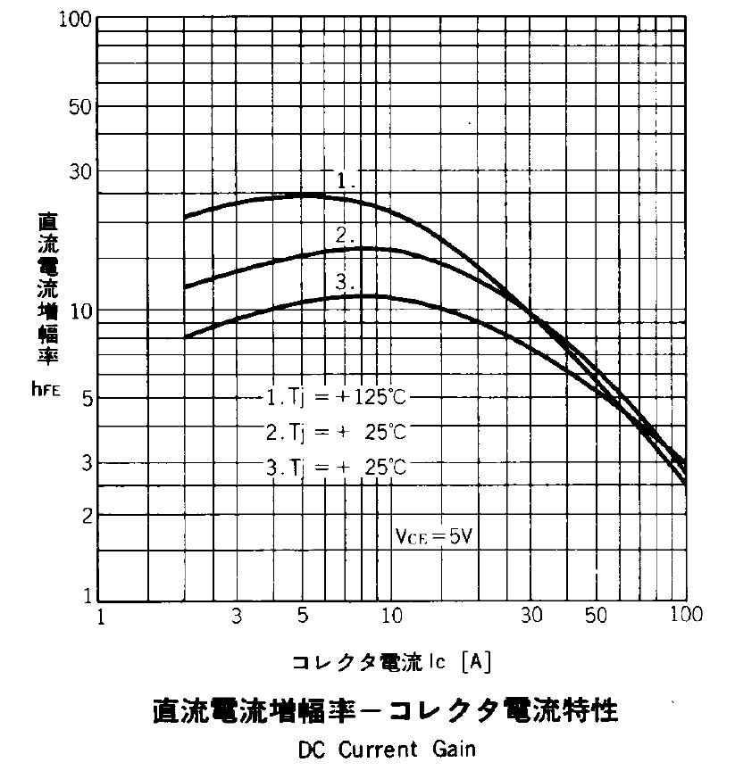
The operating current is offscale low along the left edge of the DC Current Gain plot, which suggests a DC gain under 10:
ET227 – DC Current Gain
As it turned out, the gain was around 7, with 100 mA base drive producing 700 mA of collector current at VBE = 0.9 V, although that comes from the bench supply’s low-res meters. There being an exponential relation between the bench supply’s voltage output and the transistor’s base current, along with the motor’s square-law positive feedback, speed control was mmmm touchy.
So the challenge will be stuffing 100 mA into a 1 V base voltage, with much better resolution and much less ripple than the usual Arduino PWM output, from an isolated supply. Given the amount of power I’m willing to burn in the ET227, a few more watts of base drive won’t make a bit of difference.
Perhaps the best way to handle all the nonlinearities in the current control path will be an isolated current feedback monitor. Hello, Hall effect sensors … [sigh]
The last time around, this involved silver soldering the boom wire directly to the mic housing. This time, I filed a fishmouth in the smaller tube and epoxied it to the tube that’ll hold the mic capsule:
Bike Helmet Mic Boom – housing
The smaller tube is a loose slip fit for #10 copper wire, but that’s really too heavy for the boom. I’ll probably nestle #12 wire inside another tube and epoxy that whole affair in place.
The mic capsule tube needs a rounded notch filed in one end to accommodate the wire.
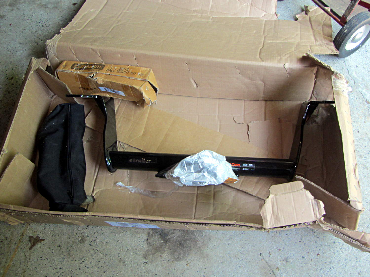
Even though it’s really hard to damage a trailer hitch made of 5/16 inch welded steel plate, that hitch made a mess out of the cardboard box:
Trailer hitch receiver – as received
It’s a Class III hitch with specs (3500 pound max, 525 pound tongue weight) that greatly exceed the Forester’s ratings (1500/150 pound), but it seems to be the only way to get a 2 inch receiver socket. I have no intention whatsoever of towing anything I can’t see over and around.
This is part of the “how to haul the recumbents” solution. Trailer hitch racks require a receiver with a tongue rating of twice the static load; a pair of Tour Easy ‘bents and most of the racks weigh in pretty close to the Subaru OEM 150 pound rating.
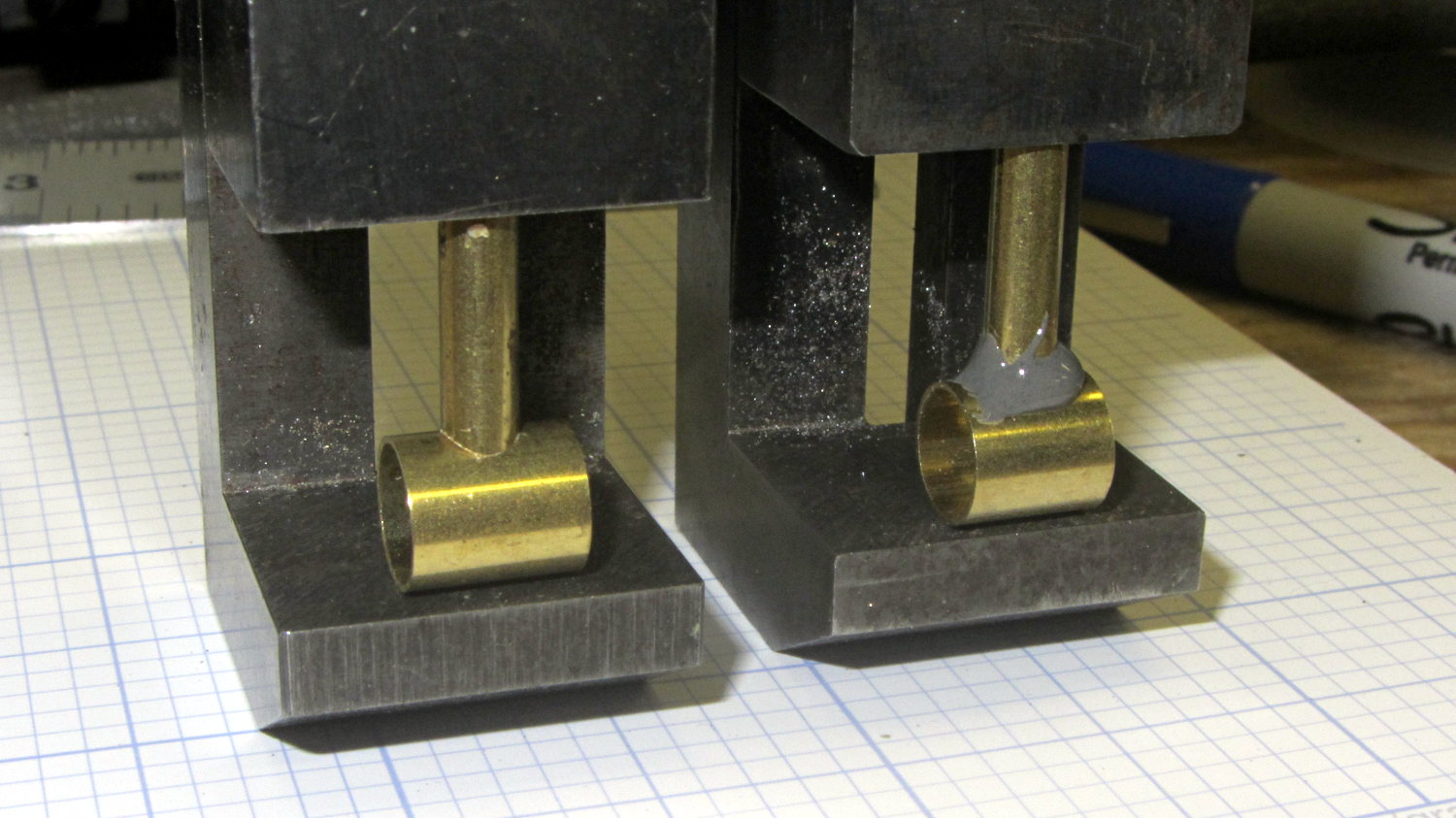
The sewing machine motor drives the handwheel through a double pulley on a jackshaft:
Kenmore 158 – handwheel – jackshaft pulley
I’ve been figuring a 10:1 speed reduction, based on counting revolutions and ignoring belt slip. The correct answer also depends on belt tension and whether you turn the motor or the handwheel.
Measuring the pulley diameters isn’t straightforward, because the belt runs deep in the handwheel pulley (the brown smudge is near the rim, above) and high on the motor pulley:
Kenmore 158 – NEMA 23 stepper – on adapter
Measuring across the tops of the belt ribs on the pulleys gives these diameters:
Motor: 18 (or 16.6 at the belt midline = pulley OD)
Jackshaft large: 48
Jackshaft small: 24
Handwheel: 75
The end-to-end ratio is either 8.3 or 9, depending on what you call the motor pulley. Either of those are close enough to 10:1 to allow for a turn or two of motor pulley slippage.
Flipping the jackshaft pulley doesn’t quite work, as the pulley ends aren’t symmetrical, but I think it can be forced to align with the handwheel if I add a lathe-turned hoodickie. If so, then the end-to-end speed ratio drops to a little over 2:1 and the original belts fit just fine:
Kenmore 158 – reversed jackshaft pulley
The maximum handwheel speed ran a bit under 1000 RPM, so the reduced ratio lets the motor turn at 2000 RPM. That’s well within range of a NEMA 23 brushless DC motor, but it must also satisfy the other non-obvious requirements:
Acoustic = no squeals, not even a little bit
Physical = a scant 100 mm from mounting plate to edge of the frame casting for a 57 mm diameter cylinder
Measuring the torque required to drive the sewing machine would go a long way toward finding the proper motor. The LeadshineBLM57050 would drop in, the BLM57090 might barely fit with some filing of a rib in the machine’s base, the and the BLM57130 isn’t in the running. The OEM motor dataplate says it’s 110 – 120 V @ 1 A = 110 – 120 W, but that surely doesn’t mean the same thing as the 130 W rating for the BLM57130.
I should just buy a motor and driver brick to see what it’s like … [sigh]