The HQ Sixteen has much larger bobbins than Mary’s Kenmore and Juki sewing machines. It also came with a dedicated bobbin winder:
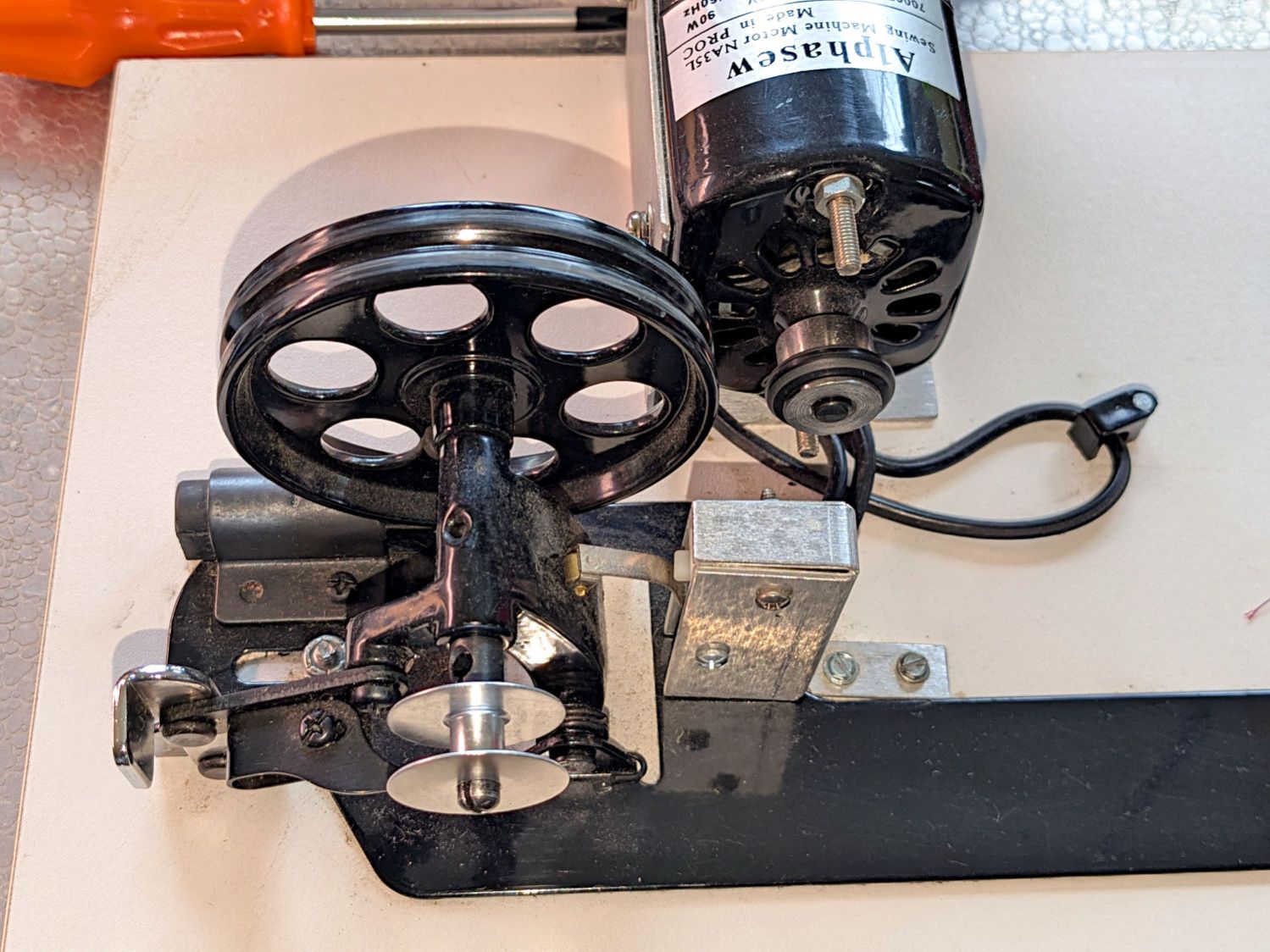
That thing has a distinct Industrial Revolution aspect compared to the BarbieCore bobbin winder I laid hands on a while ago.
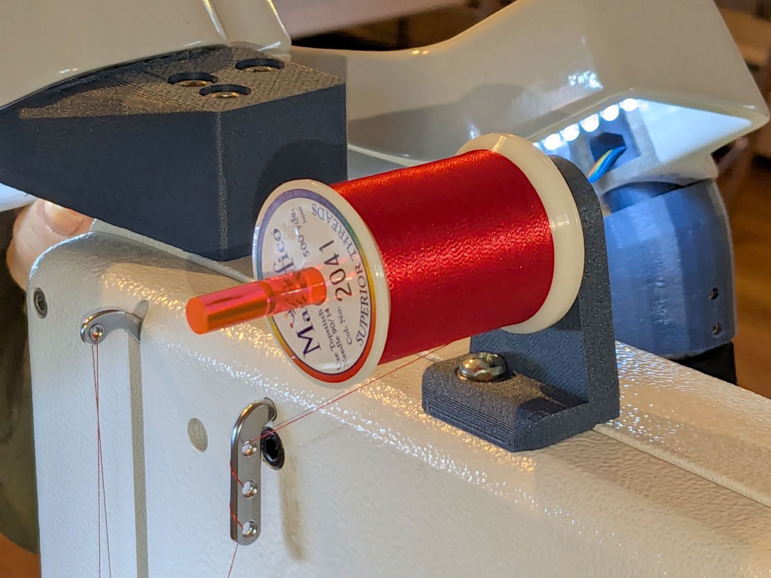
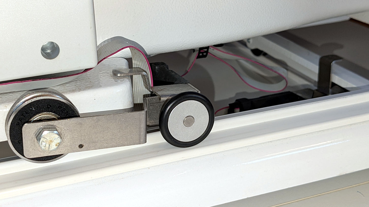
Out of the photo on the right:
- The thread cone and guide tower
- The thread tension disks
Mary had been having trouble winding the bobbins, as the tension seemed entirely too low and the thread did not lay smoothly across the bobbin, so she asked me to take a look.
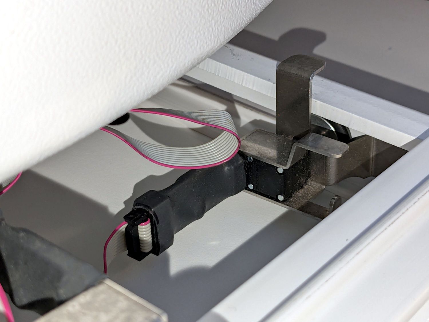
The motor shaft has an O-ring for friction drive against the large wheel driving the shaft with the bobbin on the other end. The small silver lever over on the left flips an over-center lock pressing the wheel against the O-ring and tripping the microswitch in the aluminum housing, thus turning the motor on. The bobbin fills until a small finger monitoring the thread level flips the lock back over center, the wheel disengages, the switch turns the motor off, and a spring drives the wheel against the rubber rod in the upper left.
Which worked well, but all the bobbins had a loose-to-sloppy fit on the shaft, to the extent that the shaft really couldn’t drive them against any thread tension.
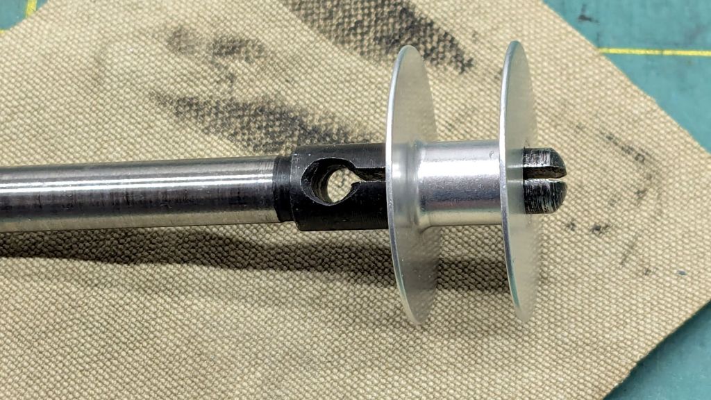
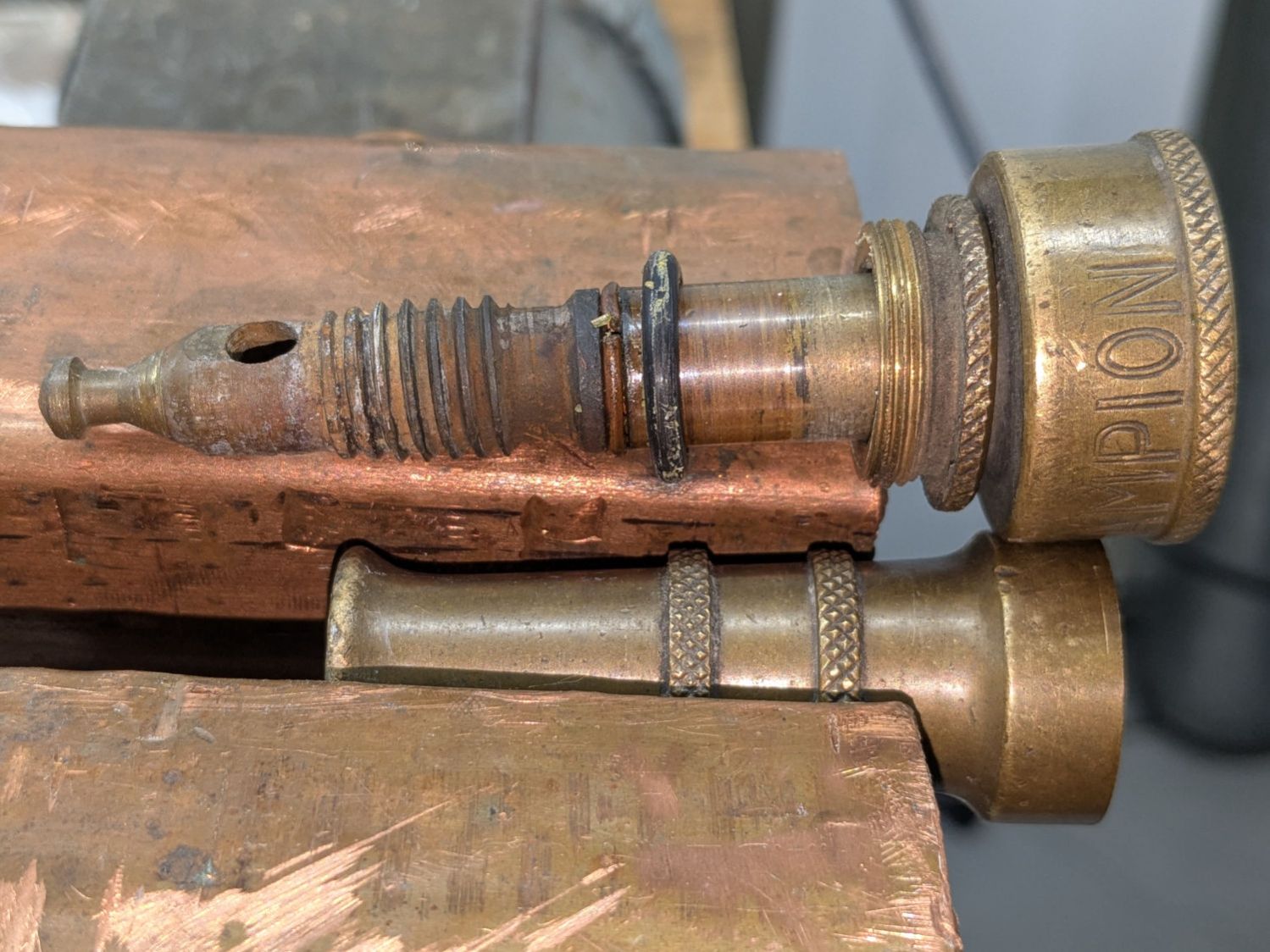
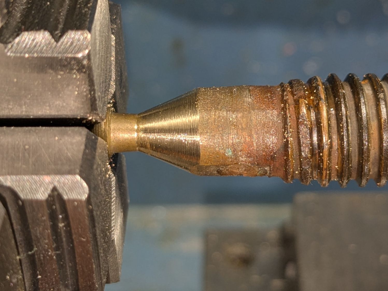
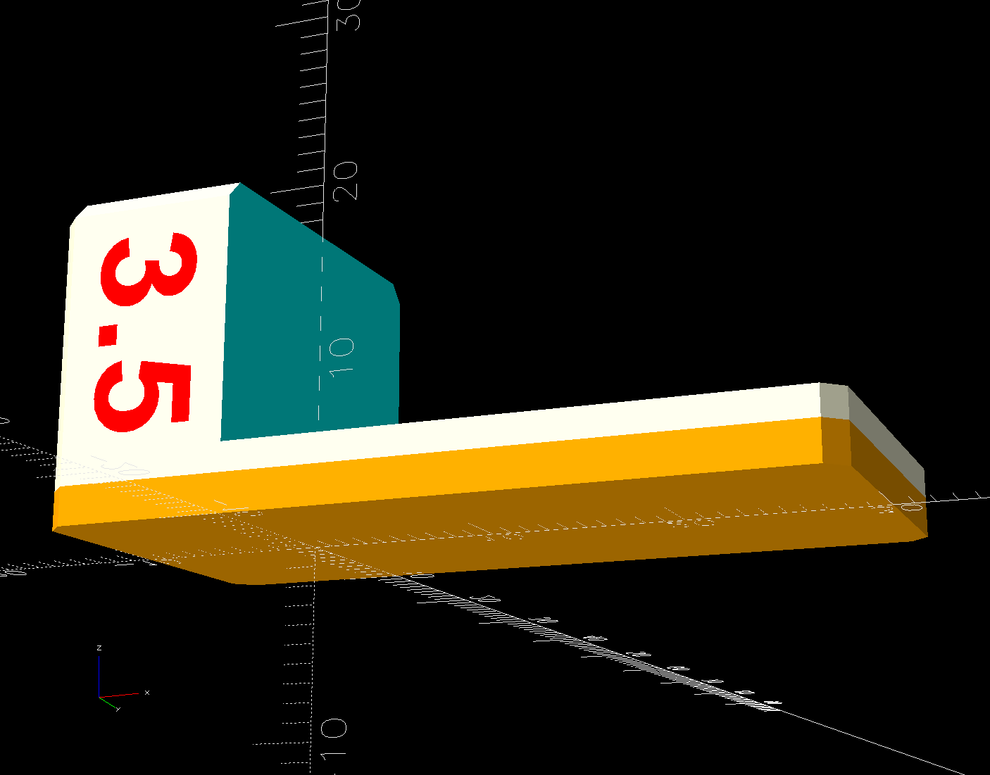
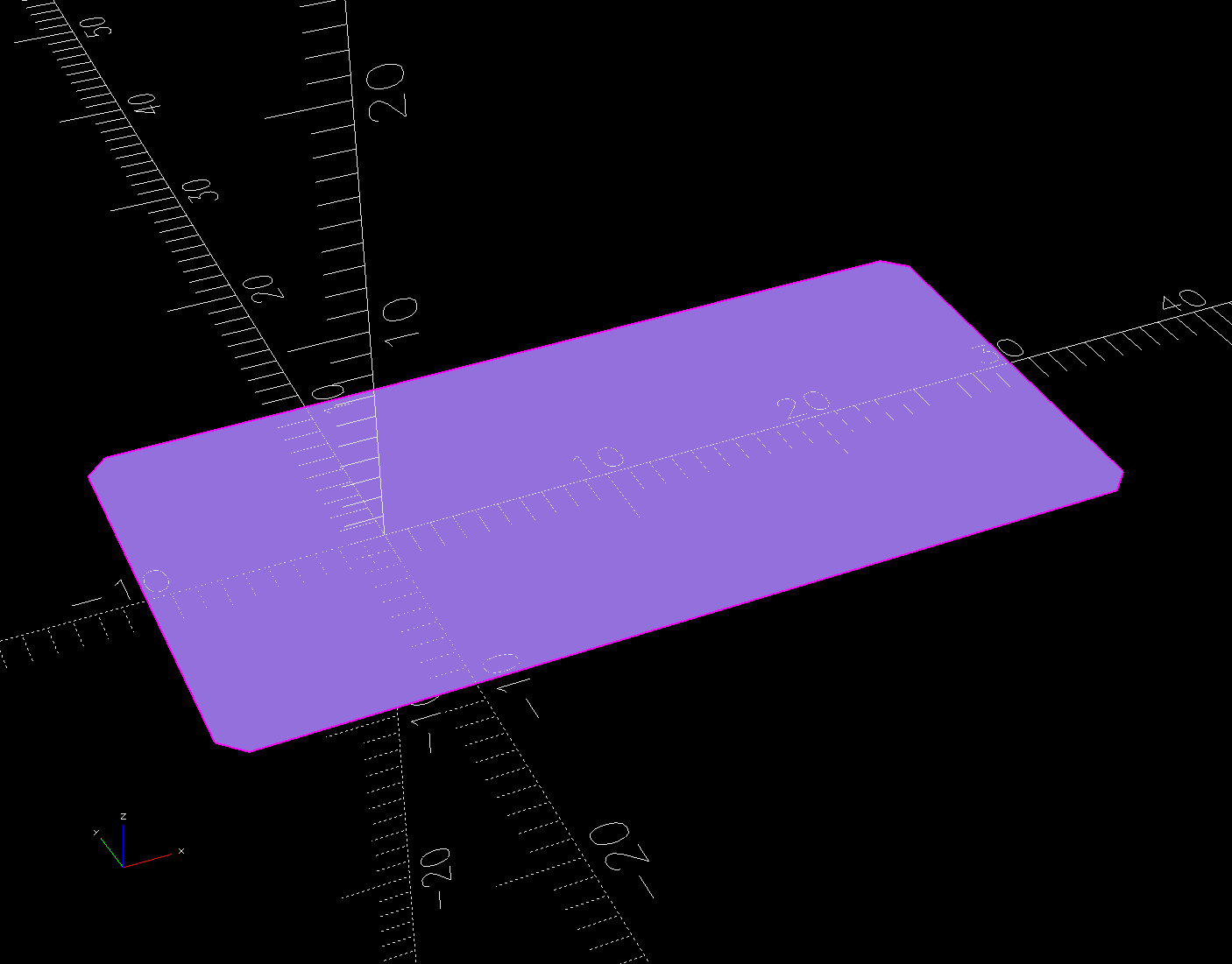
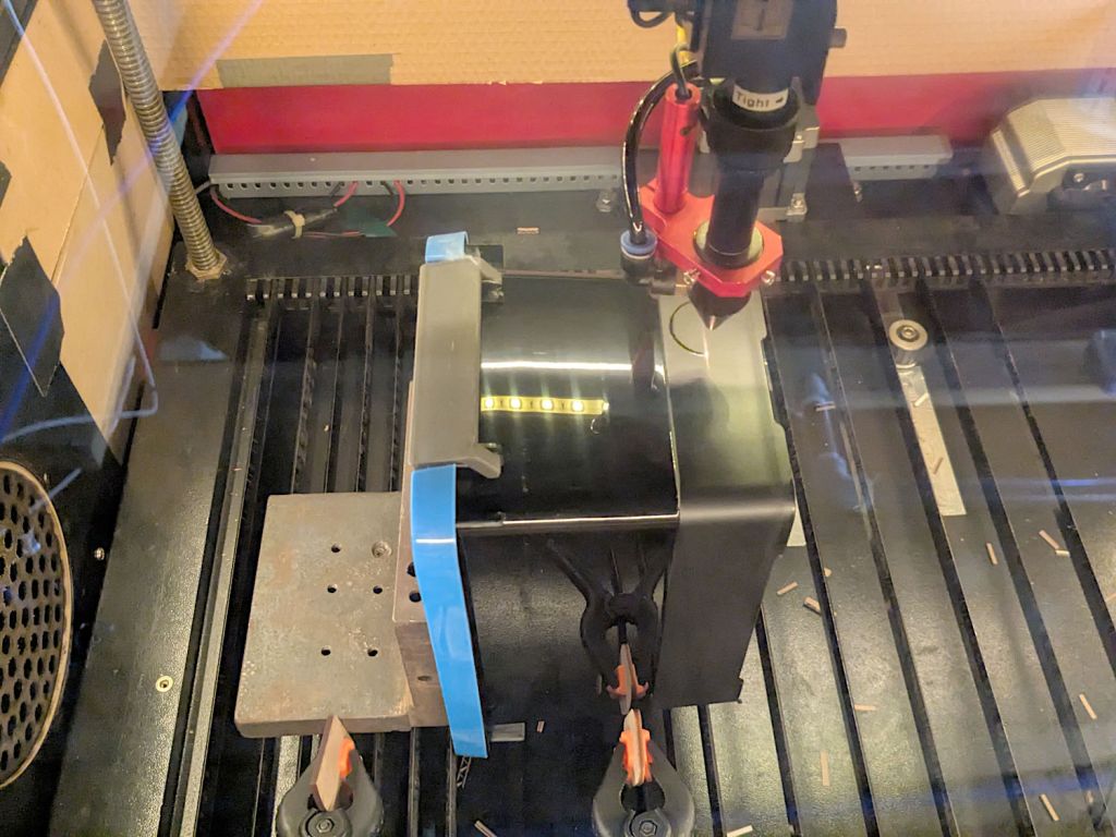
Loosening the screw holding the drive wheel on the shaft lets it slip off and the shaft slides out to the front:
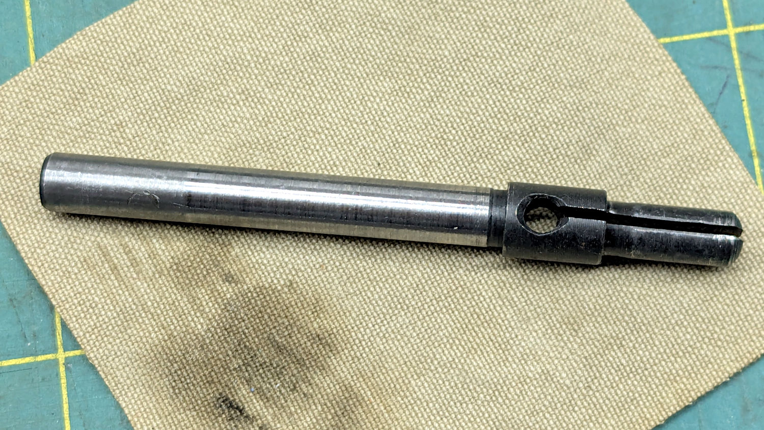
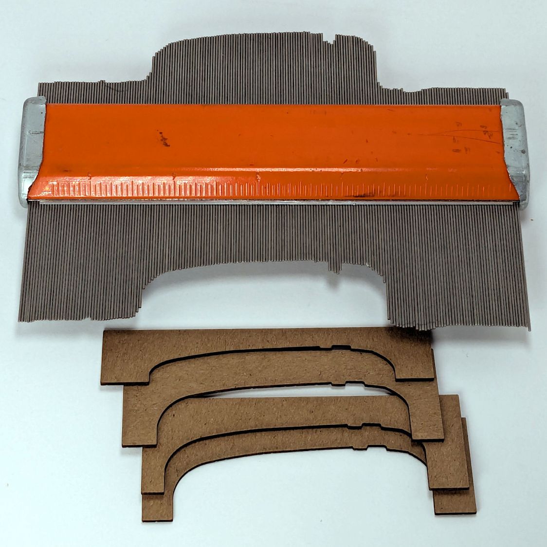
The sides of the split shaft should press firmly against the bobbin core, but that just wasn’t happening.
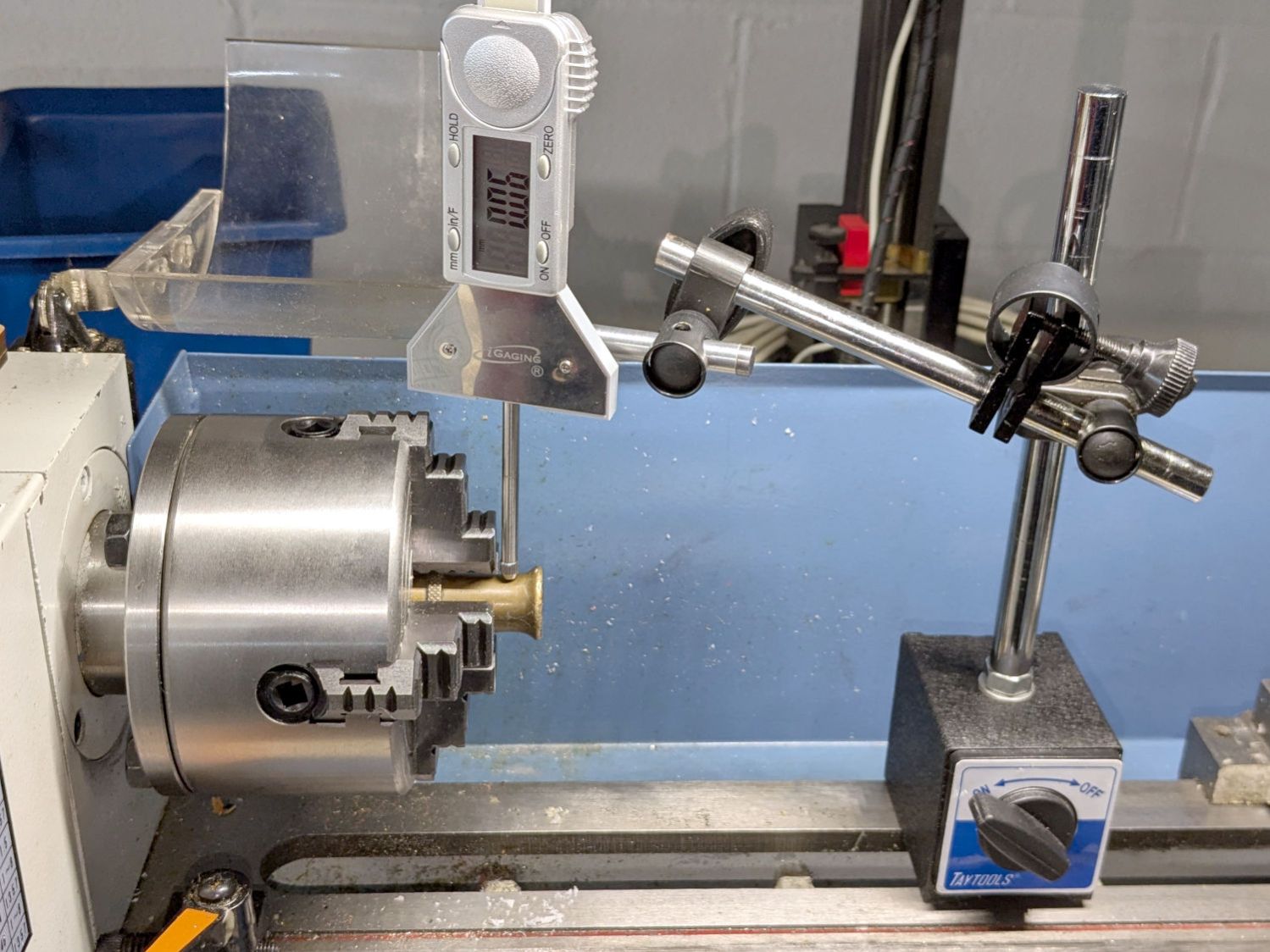
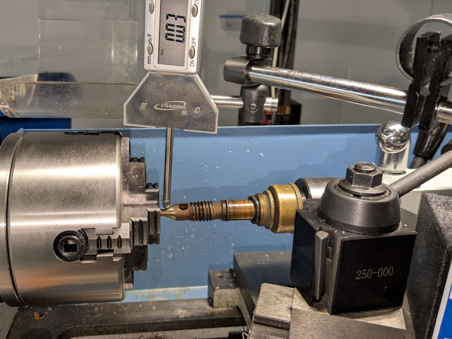
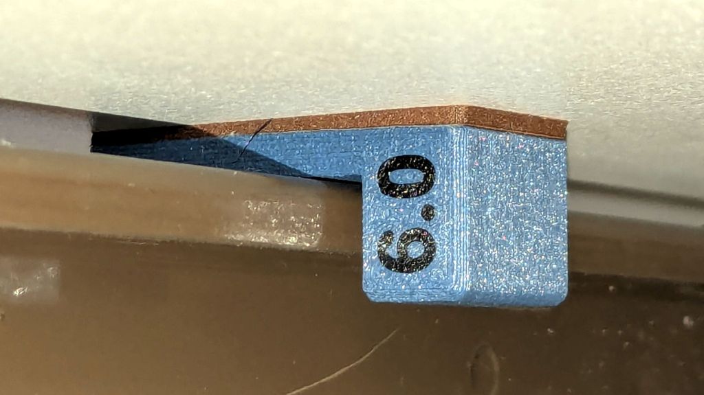
Measuring a dozen bobbins showed most had an ID of 6.04 mm, with a few around 6.01 mm; unsurprisingly, the latter had the best, albeit still loose, fit. Conversely, the split shaft had two isolated points 6.01 mm apart across a diameter, with the remainder around 5.95 mm. Those are not large differences, but it was obvious why the bobbins didn’t wind correctly.
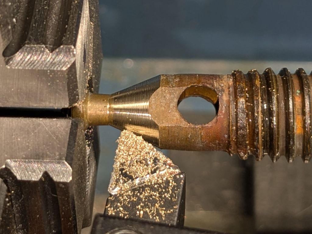
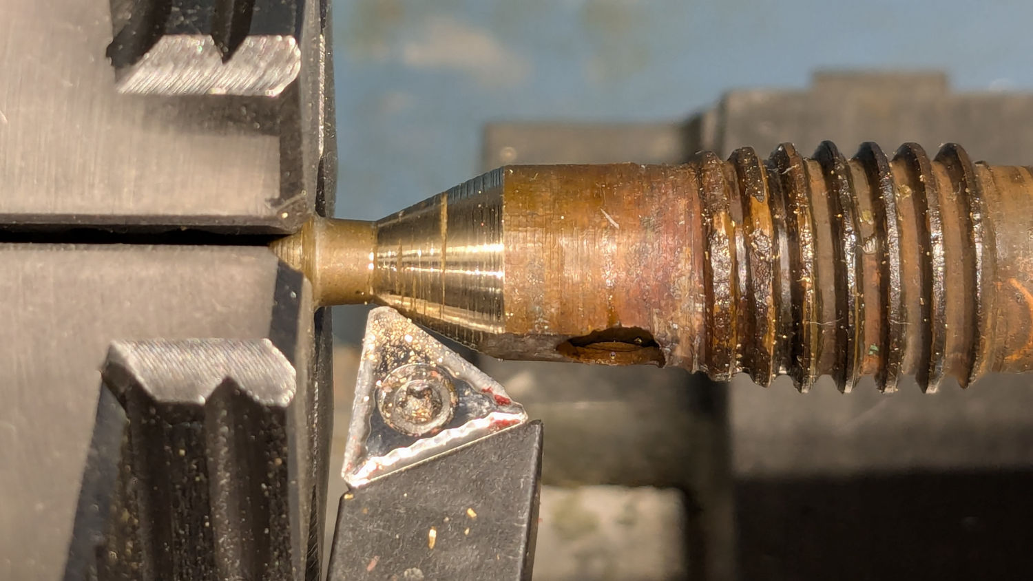
I filed some graunch off the split edges, then gently pushed the Designated Prydriver into the end of the split to spread the sides juuuust a little bit, until all the bobbins pushed on firmly and fit snugly:

It reassembled in reverse order and we’ll see how it behaves during the next marathon bobbin-filling session.


