The Smell of Molten Projects in the Morning

Ed Nisley's Blog: Shop notes, electronics, firmware, machinery, 3D printing, laser cuttery, and curiosities. Contents: 100% human thinking, 0% AI slop.

Category: Machine Shop

Mechanical widgetry

  • Kenmore 158 Needle LEDs: First Light

    With the boost converter mounted and the needle LEDs wired up:

     Kenmore 158 Needle Light - heatsink
    Kenmore 158 Needle Light – heatsink

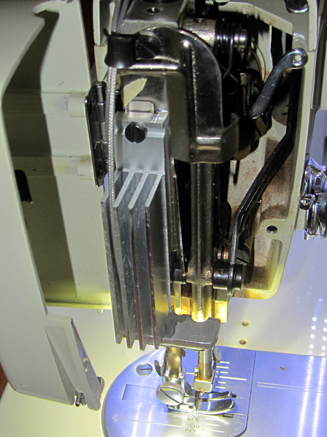
    The Kenmore 158 sewing machine crash test dummy has plenty of light:

    Kenmore 158 LED Lighting - first light
    Kenmore 158 LED Lighting – first light

    Well, as long as you don’t mind the clashing color balance. The needle LEDs turned out warmer than I expected, but Mary says she can cope. I should build a set of warm-white LED strips when it’s time to refit her real sewing machine and add another boost supply to drive them at their rated current.

    Much to our relief, the two LEDs at the needle don’t cast offensively dark shadows:

    Kenmore 158 LED Lighting - detail
    Kenmore 158 LED Lighting – detail

    All in all, it looks pretty good.

  • Generic PCB Holder: Boost Power Supply

    The DC-DC boost power supply for the LED needle lights has four mounting holes, two completely blocked by the heatsink and the others against components with no clearance for screw heads, soooo

    3D printing to the rescue:

    Boost converter - installed
    Boost converter – installed

    Now that the hulking ET227 operates in saturation mode, I removed the blower to make room for the power supply. Two strips of double-stick foam tape fasten the holder to the removable tray inside the Dell GX270’s case.

    It’s basically a rounded slab with recesses for the PCB and clearance for solder-side components:

    Boost converter mount - as printed
    Boost converter mount – as printed

    The solid model shows the screw holes sitting just about tangent to the PCB recess:

    XW029 Booster PCB Mount
    XW029 Booster PCB Mount

    That’s using the new OpenSCAD with length scales along each axis; they won’t quite replace my layout grid over the XY plane, but they certainly don’t require as much computation.

    I knew my lifetime supply of self-tapping hex head 4-40 screws would come in handy for something:

    Boost converter in mount
    Boost converter in mount

    The program needs to know the PCB dimensions and how much clearance you want for the stuff hanging off the bottom:

    PCBoard = [66,35,IntegerMultiple(1.8,ThreadThick)];
    
    BottomParts = [[1.5,-1.0,0,0],	// xyz offset of part envelope
    				[60.0,37.0,IntegerMultiple(3.0,ThreadThick)]];	// xyz envelope size (z should be generous)
    

    That’s good enough for my simple needs.

    The hole locations form a list-of-vectors that the code iterates through:

    Holes = [			// PCB mounting screw holes: XY + rotation
    		[Margin - ScrewOffset,MountBase[Y]/2,180/6],
    		[MountBase[X] - Margin + ScrewOffset/sqrt(2),MountBase[Y] - Margin + ScrewOffset/sqrt(2),15],
    		[MountBase[X] - Margin + ScrewOffset/sqrt(2),Margin - ScrewOffset/sqrt(2),-15],
    		];
    
    ... snippage ...
    
    for (h = Holes) {
    	translate([h[X],h[Y],-Protrusion]) rotate(h[Z])
    		PolyCyl(Tap4_40,MountBase[Z] + 2*Protrusion,6);
    }
    

    That’s the first occasion I’ve had to try iterating a list and It Just Worked; I must break the index habit. The newest OpenSCAD version has Python-ish list comprehensions which ought to come in handy for something.

    The “Z coordinate” of each hole position gives its rotation, so I could snuggle them up a bit closer to the edge by forcing the proper polygon orientation. The square roots in the second two holes make them tangent to the corners of the PCB, rather than the sides, which wasn’t true for the first picture. Fortunately, the washer head of those screws turned out to be just big enough to capture the PCB anyway.

    The OpenSCAD source code:

    // PCB mounting bracket for XW029 DC-DC booster
    // Ed Nisley - KE4ZNU - January 2015
    
    Layout = "Build";			// PCB Block Mount Build
    
    //- Extrusion parameters must match reality!
    //  Print with 4 shells and 3 solid layers
    
    ThreadThick = 0.20;
    ThreadWidth = 0.40;
    
    HoleWindage = 0.2;			// extra clearance
    
    Protrusion = 0.1;			// make holes end cleanly
    
    AlignPinOD = 1.70;			// assembly alignment pins: filament dia
    
    function IntegerMultiple(Size,Unit) = Unit * ceil(Size / Unit);
    
    X = 0;						// useful subscripts
    Y = 1;
    Z = 2;
    
    //----------------------
    // Dimensions
    
    inch = 25.4;
    
    Tap4_40 = 0.089 * inch;
    Clear4_40 = 0.110 * inch;
    Head4_40 = 0.211 * inch;
    Head4_40Thick = 0.065 * inch;
    Nut4_40Dia = 0.228 * inch;
    Nut4_40Thick = 0.086 * inch;
    Washer4_40OD = 0.270 * inch;
    Washer4_40ID = 0.123 * inch;
    
    PCBoard = [66,35,IntegerMultiple(1.8,ThreadThick)];
    
    BottomParts = [[1.5,-1.0,0,0],				// xyz offset of part envelope
    				[60.0,37.0,IntegerMultiple(3.0,ThreadThick)]];			// xyz envelope size (z should be generous)
    
    Margin = IntegerMultiple(Washer4_40OD,ThreadWidth);
    
    MountBase = [PCBoard[X] + 2*Margin,
    			PCBoard[Y] + 2*Margin,
    			IntegerMultiple(5.0,ThreadThick) + PCBoard[Z] + BottomParts[1][Z]
    			];
    echo("Mount base: ",MountBase);
    
    ScrewOffset = Clear4_40/2;
    
    Holes = [									// PCB mounting screw holes: XY + rotation
    		[Margin - ScrewOffset,MountBase[Y]/2,180/6],
    		[MountBase[X] - Margin + ScrewOffset/sqrt(2),MountBase[Y] - Margin + ScrewOffset/sqrt(2),15],
    		[MountBase[X] - Margin + ScrewOffset/sqrt(2),Margin - ScrewOffset/sqrt(2),-15],
    		];
    
    CornerRadius = Washer4_40OD / 2;
    
    //----------------------
    // Useful routines
    
    module PolyCyl(Dia,Height,ForceSides=0) {			// based on nophead's polyholes
    
      Sides = (ForceSides != 0) ? ForceSides : (ceil(Dia) + 2);
    
      FixDia = Dia / cos(180/Sides);
    
      cylinder(r=(FixDia + HoleWindage)/2,
               h=Height,
               $fn=Sides);
    }
    
    module ShowPegGrid(Space = 10.0,Size = 1.0) {
    
      RangeX = floor(100 / Space);
      RangeY = floor(125 / Space);
    
    	for (x=[-RangeX:RangeX])
    	  for (y=[-RangeY:RangeY])
    		translate([x*Space,y*Space,Size/2])
    		  %cube(Size,center=true);
    
    }
    
    //----------------------
    // Build things
    
    module PCB() {
    
    	union() {
    		cube(PCBoard);
    		translate(BottomParts[X] - [0,0,BottomParts[1][Z]])
    			cube(BottomParts[Y] + [0,0,Protrusion]);
    	}
    
    }
    
    module Block() {
    	translate([MountBase[X]/2,MountBase[Y]/2,0])
    		hull()
    			for (i = [-1,1], j = [-1,1])
    				translate([i*(MountBase[X]/2 - CornerRadius),j*(MountBase[Y]/2 - CornerRadius)],0)
    					cylinder(r=CornerRadius,h=MountBase[Z] - Protrusion,$fn=8*4);
    }
    
    module Mount() {
    
    	difference() {
    		Block();
    
    		translate([MountBase[X]/2 - PCBoard[X]/2 + BottomParts[0][X] - Protrusion,
    					-MountBase[Y]/2,
    					MountBase[Z] - PCBoard[Z] - BottomParts[1][Z]])
    			cube([BottomParts[1][X] + 2*Protrusion,
    					2*MountBase[Y],
    					2*BottomParts[1][Z]]);
    
    		translate([MountBase[X]/2 - PCBoard[X]/2,		// PCB recess
    					MountBase[Y]/2 - PCBoard[Y]/2,
    					MountBase[Z] - PCBoard[Z]])
    			PCB();
    		for (h = Holes) {
    			translate([h[X],h[Y],-Protrusion]) rotate(h[Z])
    				PolyCyl(Tap4_40,MountBase[Z] + 2*Protrusion,6);
    		}
    	}
    
    }
    
    //ShowPegGrid();
    
    if (Layout == "PCB")
    	PCB();
    
    if (Layout == "Block")
    	Block();
    
    if (Layout == "Mount")
    	Mount();
    
    if (Layout == "Build")
    	translate([-MountBase[X]/2,-MountBase[Y]/2,0])
    	Mount();
    
  • APRS Turn Slope Units

    There’s a fundamental error in my writeup about setting the APRS Smart Beaconing parameters for the bike trackers: I blundered the units of Turn Slope.

    Rich Painter recently explained how that works:

    I ran across your blog on Smart Beaconing and saw something that needed correction.

    You state the Turn Slope is in units Degrees / MPH

    This is incorrect. Although the term Turn Slope is not a real slope (such as rise/run classically) that is what the originators used albeit incorrectly. They do however correctly attribute the units to MPH * Degrees (a product and hence not really a slope).

    In their formula they calculate a turn threshold as:
    turn_threshold = min_turn_angle + turn_slope / speed

    Looking at the units we see:
    = Degrees + (MPH * Degrees) / MPH

    which yields
    = Degrees + Degrees

    Which makes sense. It is too bad that the originators used the wrong term of Turn Slope which confuses most people. A better term would have been Turn Product.

    In looking back over that post, I have no idea where or how I got the wrong units, other than by the plain reading of the “variable name”.

    As he explained in a followup note:

    As for units… I was introduced to making unit balance way back in 1967-1968 science class in HS by a really fine science teacher. It has served me all my life and I’m thankful for that training.

    I have ever since told that teacher so!

    A while back, our Larval Engineer rammed an engineering physics class head-on and sent me a meme image, observing that I’d trained her well: if the units don’t work out, then you’re doing it wrong.

    Yes, yes, I do care about the units:

    Give a shit about the units
    Give a shit about the units
  • Kenmore 158 UI: Automatic Button Builder

    Given the glacially slow Arduino touch-screen TFT display as a first pass UI for the Kenmore 158 sewing machine, I need some UI elements.

    I need buttons. Lots of buttons.

    Each button will have several different states that must be visually distinct:

    • Disabled – not available for pressing
    • Released – can be pressed and is inactive
    • Pressed – has been pressed and is now active

    There may be other states, but those should be enough to get started.

    I’d rather not draw that detail by hand for each button, so some tinkering with the Bash script driving the Imagemagick routines produced these results:

    Buttons
    Buttons

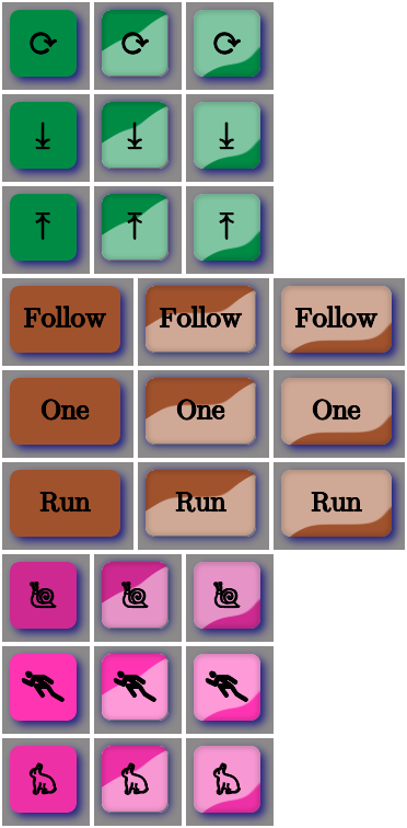
    Aren’t those just the ugliest buttons you’ve ever seen?

    The garish colors identify different functions, the crude shading does a (rather poor) job of identifying the states, and the text & glyphs should be unambiguous in context. Obviously, there’s room for improvement.

    The point is that I can begin building the UI code that will slap those bitmaps on the Arduino’s touch-panel LCD while responding to touches, then come back and prettify the buttons as needed. With a bit of attention to detail, I should be able to re-skin the entire UI without building the data into the Arduino sketch, but I’ll start crude.

    The mkAll.sh script that defines the button characteristics and calls the generator script:

    ./mkBFam.sh NdDn springgreen4 ⤓
    ./mkBFam.sh NdUp springgreen4 ⤒
    ./mkBFam.sh NdAny springgreen4 ⟳ 80 80 40
    ./mkBFam.sh PdOne sienna One 120 80
    ./mkBFam.sh PdFol sienna Follow 120 80
    ./mkBFam.sh PdRun sienna Run 120 80
    ./mkBFam.sh SpMax maroon1  🏃 80 80 40
    ./mkBFam.sh SpMed maroon2  🐇 80 80 40
    ./mkBFam.sh SpLow maroon3  🐌
    montage *bmp -tile 3x -geometry +2+2 Buttons.png
    display Buttons.png
    

    As before, if you don’t see rabbit and snail glyphs, then your fonts don’t cover those Unicode blocks.

    The quick-and-dirty mkBFam.sh script that produces three related buttons for each set of parameters:

    # create family of simple beveled buttons
    # Ed Nisley - KE4ZNU
    # January 2015
    
    [ -z $1 ] && FN=Test || FN=$1
    [ -z $2 ] && CLR=red || CLR=$2
    [ -z $3 ] && TXT=x   || TXT=$3
    [ -z $4 ] && SX=80   || SX=$4
    [ -z $5 ] && SY=80   || SY=$5
    [ -z $6 ] && PT=25   || PT=$6
    [ -z $7 ] && BDR=10  || BDR=$7
    
    echo fn=$FN clr=$CLR txt=$TXT sx=$SX sy=$SY pt=$PT bdr=$BDR
    
    echo Working ...
    
    echo Shape
    convert -size ${SX}x${SY} xc:none \
    -fill $CLR -draw "roundrectangle $BDR,$BDR $((SX-BDR)),$((SY-BDR)) $((BDR-2)),$((BDR-2))" \
    ${FN}_s.png
    
    echo Highlights
    convert ${FN}_s.png \
      \( +clone -alpha extract -blur 0x12 -shade 110x2 \
      -normalize -sigmoidal-contrast 16,60% -evaluate multiply .5\
      -roll +4+8 +clone -compose Screen -composite \) \
      -compose In  -composite \
      ${FN}_h.png
    
    convert ${FN}_s.png \
      \( +clone -alpha extract -blur 0x12 -shade 110x0 \
      -normalize -sigmoidal-contrast 16,60% -evaluate multiply .5\
      -roll +4+8 +clone -flip -flop -compose Screen -composite \) \
      -compose In  -composite \
      ${FN}_l.png
    
    echo Borders
    convert ${FN}_h.png \
      \( +clone -alpha extract  -blur 0x2 -shade 0x90 -normalize \
      -blur 0x2  +level 60,100%  -alpha On \) \
      -compose Multiply -composite \
       ${FN}_bh.png
    
    convert ${FN}_l.png \
      \( +clone -alpha extract  -blur 0x2 -shade 0x90 -normalize \
      -blur 0x2  +level 60,100%  -alpha On \) \
      -compose Multiply -composite \
       ${FN}_bl.png
    
    echo Buttons
    convert ${FN}_s.png \
      -font /usr/share/fonts/custom/Symbola.ttf  -pointsize ${PT}  -fill black  -stroke black \
      -gravity Center  -annotate 0 "${TXT}"  -trim -repage 0x0+7+7 \
      \( +clone -background navy -shadow 80x4+4+4 \) +swap \
      -background snow4  -flatten \
      ${FN}0.png
    
    convert ${FN}_bl.png \
      -font /usr/share/fonts/custom/Symbola.ttf  -pointsize ${PT}  -fill black  -stroke black \
      -gravity Center  -annotate 0 "${TXT}"  -trim -repage 0x0+7+7 \
      \( +clone -background navy -shadow 80x4+4+4 -flip -flop \) +swap \
      -background snow4  -flatten \
      ${FN}1.png
    
    convert ${FN}_bh.png \
      -font /usr/share/fonts/custom/Symbola.ttf  -pointsize $PT  -fill black  -stroke black \
      -gravity Center  -annotate 0 "${TXT}"  -trim -repage 0x0+7+7 \
      \( +clone -background navy -shadow 80x4+4+4 \) +swap \
      -background snow4  -flatten \
      ${FN}2.png
    
    echo BMPs
    for ((i=0 ; i <= 2 ; i++))
    do
     convert ${FN}${i}.png -type truecolor ${FN}${i}.bmp
    # display -resize 300% ${FN}${i}.bmp
    done
    
    echo Done!
    

    Now, to get those bitmaps from the SD card into the proper place on the LCD panel…

  • Monthly Image: Spherometer Measurements

    Our Larval Engineer volunteered to convert the lens from a defunct magnifying desk lamp into a hand-held magnifier; there’s more to that story than is relevant here. I bulldozed her into making a solid model of the lens before starting on the hand-holdable design, thus providing a Thing to contemplate while working out the holder details.

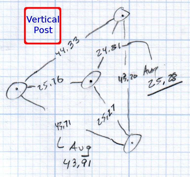
    That justified excavating a spherometer from the heap to determine the radius of curvature for the lens:

    Student Sphereometer on lens
    Student Sphereometer on lens

    You must know either the average radius / diameter of the pins or the average pin-to-pin distance. We used a quick-and-dirty measurement for the radius, but after things settled down, I used a slightly more rigorous approach. Spotting the pins on carbon paper (!) produced these numbers:

    Sphereometer Pin Radii
    Sphereometer Pin Radii

    The vertical scale has hard-metric divisions: 1 mm on the post and 0.01 on the dial. You’d therefore expect the pins to be a hard metric distance apart, but the 25.28 mm average radius suggests a crappy hard-inch layout. It was, of course, a long-ago surplus find without provenance.

    The 43.91 mm average pin-to-pin distance works out to a 50.7 mm bolt circle diameter = 25.35 mm radius, which is kinda-sorta close to the 25.28 mm average radius. I suppose averaging the averages would slightly improve things, but …

    The vertical distance for the lens in question was 0.90 mm, at least for our purposes. That’s the sagitta, which sounds cool enough to justify this whole exercise right there. It’s 100 mm in diameter and the ground edge is 2.8 mm thick, although the latter is subject to some debate.

    Using the BCD, the chord equation applies:

    • Height m = 0.90 mm
    • Base c = 50.7 mm
    • Lens radius r = (m2 + c2/4) / 2m = 357.46 mm

    Using the pin-to-pin distance, the spherometer equation applies:

    • Pin-to-pin a = 43.91 mm
    • Sagitta h = 0.90 mm
    • Lens radius R = (h/2) + (a2 / 6h) = 357.50 mm

    Close enough, methinks.

    Solving the chord equation for the total height of each convex side above the edge:

    • Base c = 100 mm
    • Lens radius r = 357.5 mm
    • Height m = r – sqrt(r2 -c2/4) = 3.5 mm

    So the whole lens should be 2 · 3.5 + 2.8 = 9.8 mm thick. It’s actually 10.15 mm, which says they were probably trying for 10.0 mm and I’m measuring the edge thickness wrong.

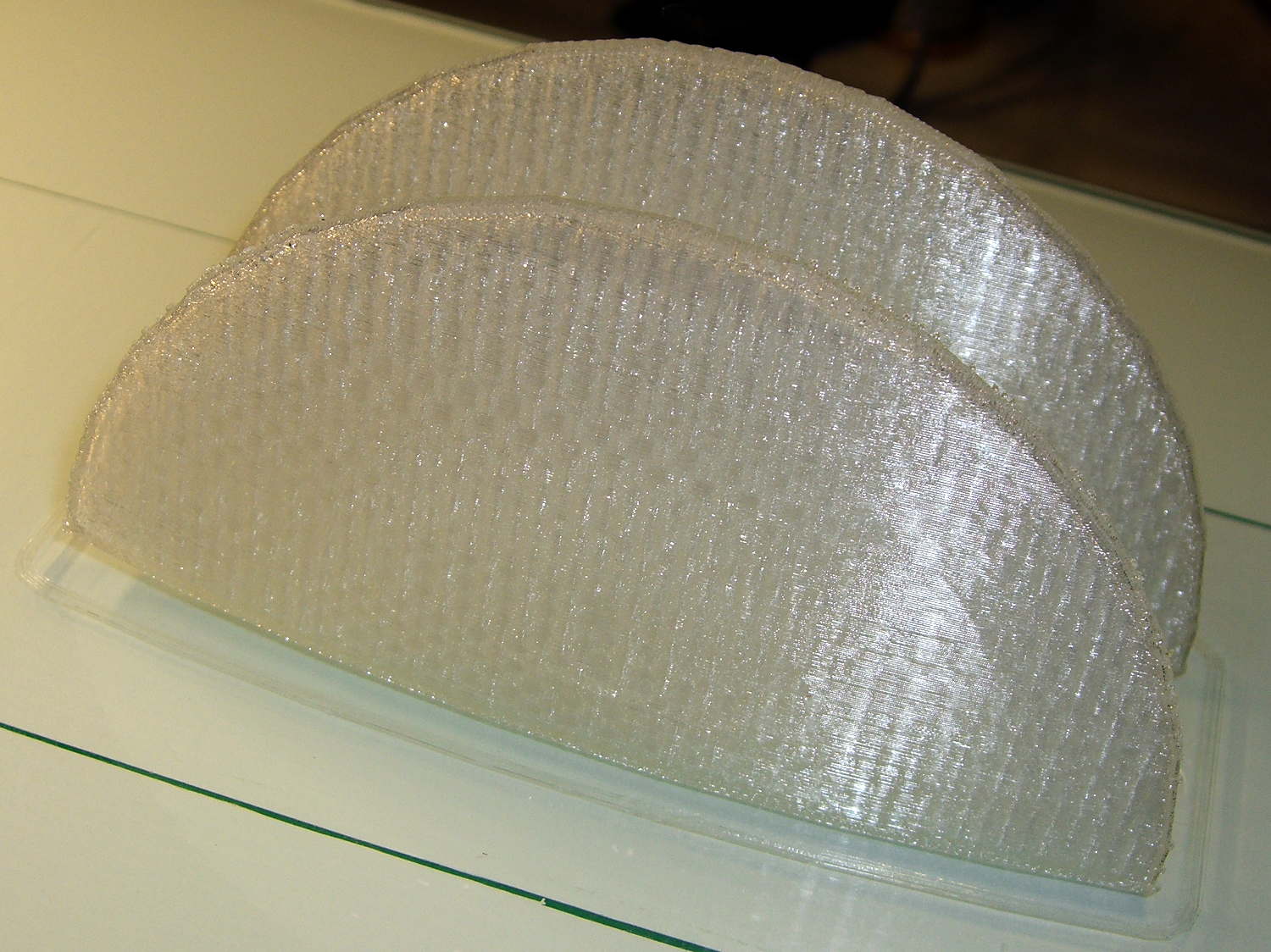
    She submitted to all this nonsense with good grace and cooked up an OpenSCAD model that prints the “lens” in two halves:

    Printed Lens - halves on platform
    Printed Lens – halves on platform

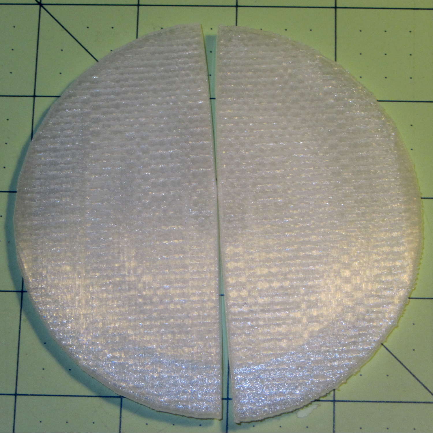
    Alas, those thin flanges have too little area on the platform to resist the contraction of the plastic above, so they didn’t fit together very well at all:

    Printed Lens - base distortion
    Printed Lens – base distortion

    We figured a large brim would solve that problem, but then it was time for her to return to the hot, fast core of college life…

  • Kenmore 158: Useful Unicode Glyphs

    It turns out, for some reasons that aren’t relevant here, that I’ll be using the Adafruit Arduino LCD panel for the sewing machine control panel, at least to get started. In mulling that over, the notion of putting text on the buttons suggests using getting simple pictures with Unicode characters.

    Herewith, some that may prove useful:

    • Needle stop up: ↥ = U+21A5
    • Needle stop up: ⤒=U+2912
    • Needle stop down: ⤓ = U+2913
    • Needle stop any: ↕ = U+2195
    • Needle stop any: ⟳ = U+27F3
    • Needle stop any: ⇅ = U+21C5
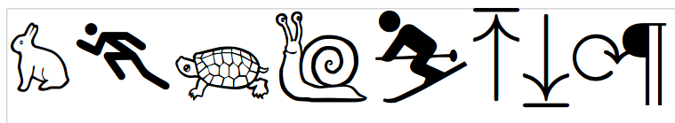
    • Rapid speed: ⛷ = U+26F7 (skier)
    • Rapid speed: 🐇  = U+1F407 (rabbit)
    • Slow speed: 🐢 = U+1F422 (turtle)
    • Dead slow: 🐌 = U+1F40C (snail)
    • Maximum speed: 🏃 = U+1F3C3 (runner)
    • Bobbin: ⛀ = U+26C0 (white draughts man)
    • Bobbin: ⛂ = U+26C2 (black draughts man)
    • Bobbin winding: 🍥 = U+1F365 (fish cake with swirl)

    Of course, displaying those characters require a font with deep Unicode support, which may explain why your browser renders them as gibberish / open blocks / whatever. The speed glyphs look great on the Unicode table, but none of the fonts around here support them; I’m using the Droid font family to no avail.

    Blocks of interest:

    The links in the fileformat.info table of Unicode blocks lead to font coverage reports, but I don’t know how fonts get into those reports. The report for the Miscellaneous Symbols block suggested the Symbola font would work and a test with LibreOffice show it does:

    Symbola font test
    Symbola font test

    An all-in-one-page Unicode symbol display can lock up your browser hard while rendering a new page.

    Unicode is weird

  • 3D Printed Handcuffs

    A friend who read about my chain mail armor asked about handcuffs, so I ran off one of gianteye’s Printable Handcuffs V1.0:

    3D Printed Handcuff
    3D Printed Handcuff

    Alas, that shows the difficulty of using an STL file designed for a different printer, as the interlocking parts didn’t even come close to fitting and required major abrasive adjustment with a Dremel. One of the few successful prints reported on Thingiverse seems involve a commercial printer, so it’s not just the M2’s problem.

    I’m not sufficiently motivated to conjure an OpenSCAD model right now…