The 3D printed Clover Mini-Iron holder served well over the last decade (!), even after one of Mary’s buddies misplaced the iron during a quilting bee:
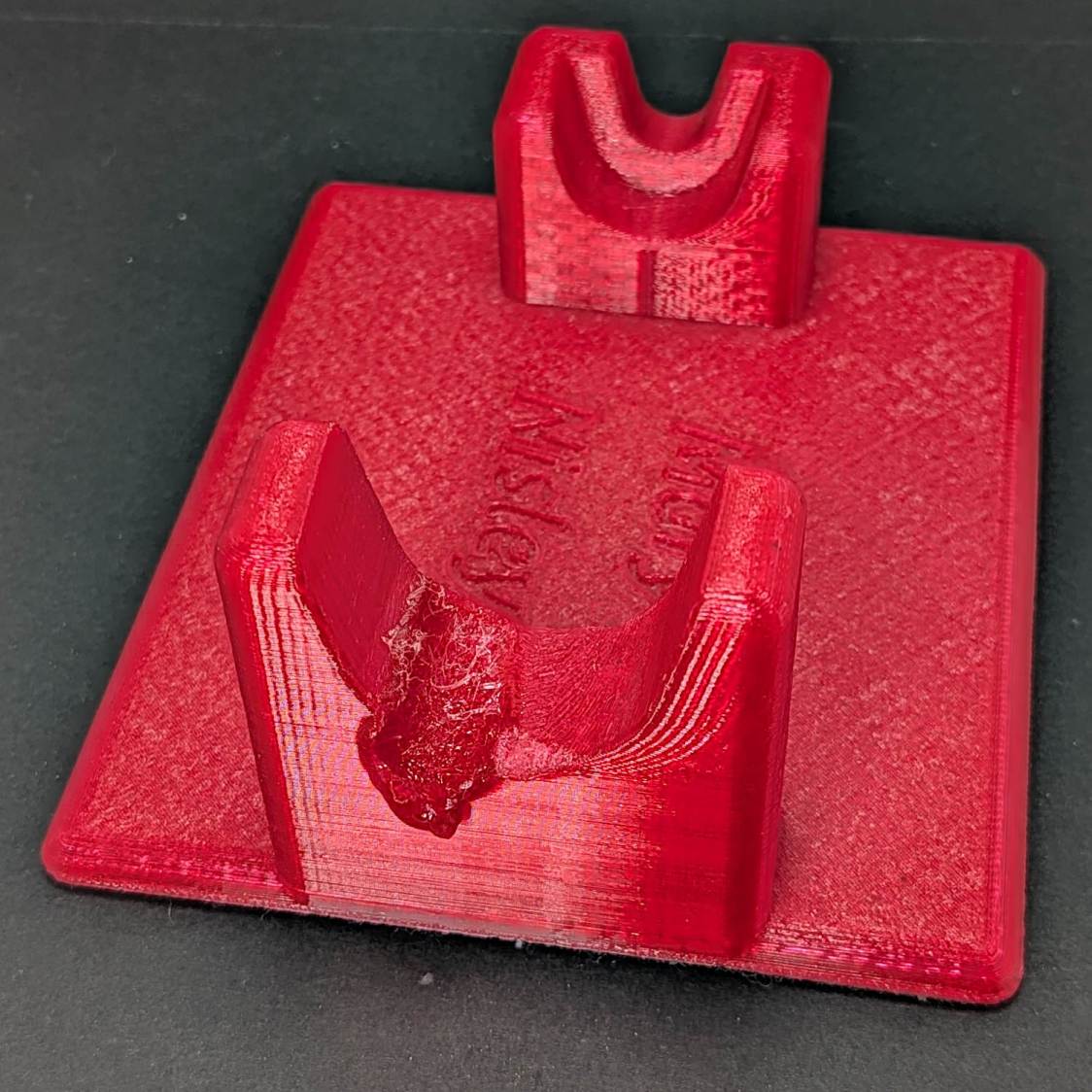
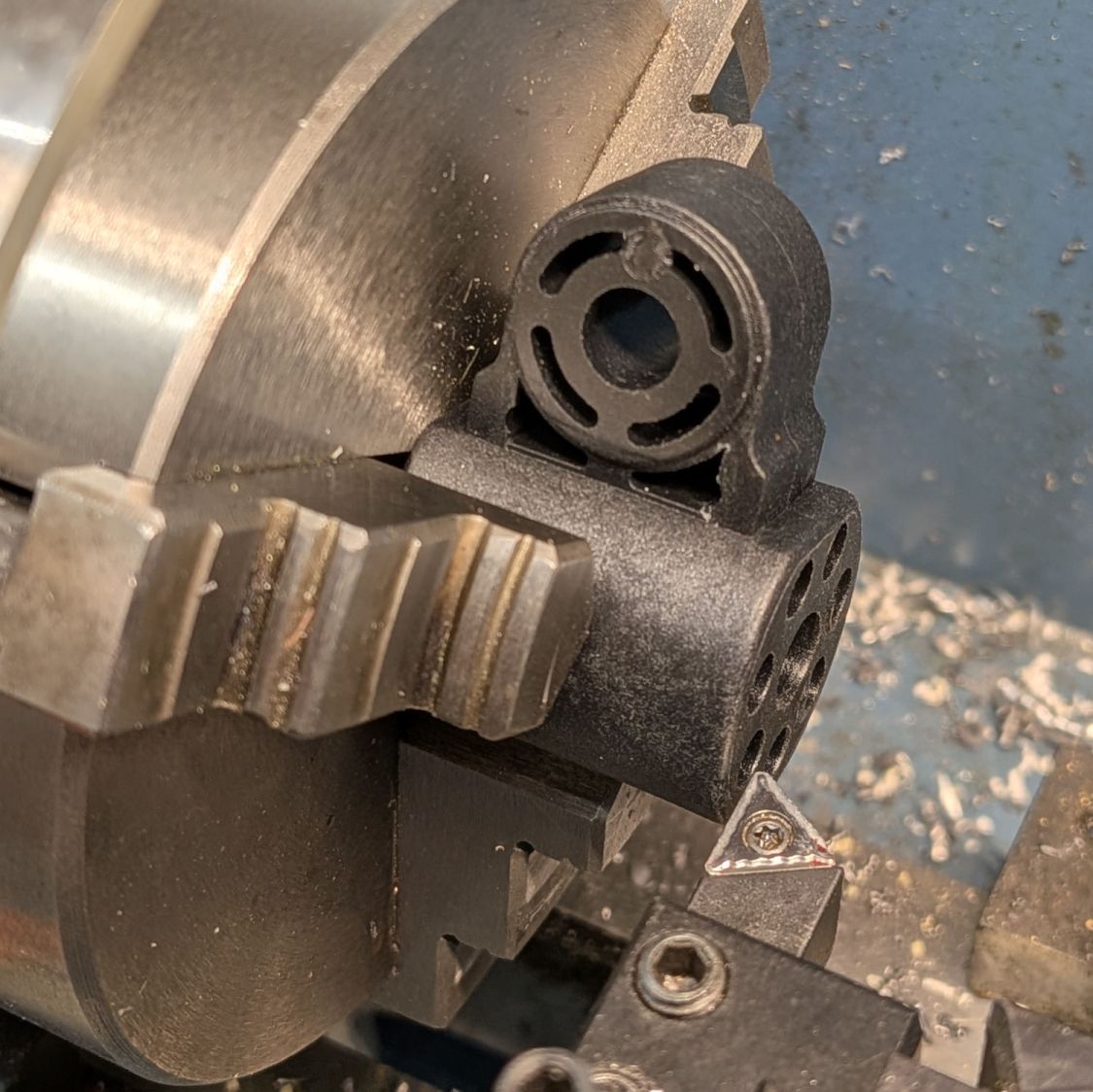
She asked for a new holder that put the iron at a higher angle for easier gripping, which required only slight tinkering to boot the OpenSCAD code into the current decade:
The letters stand one layer proud of the surface just to see what that looked like. I think it’s a nice touch.
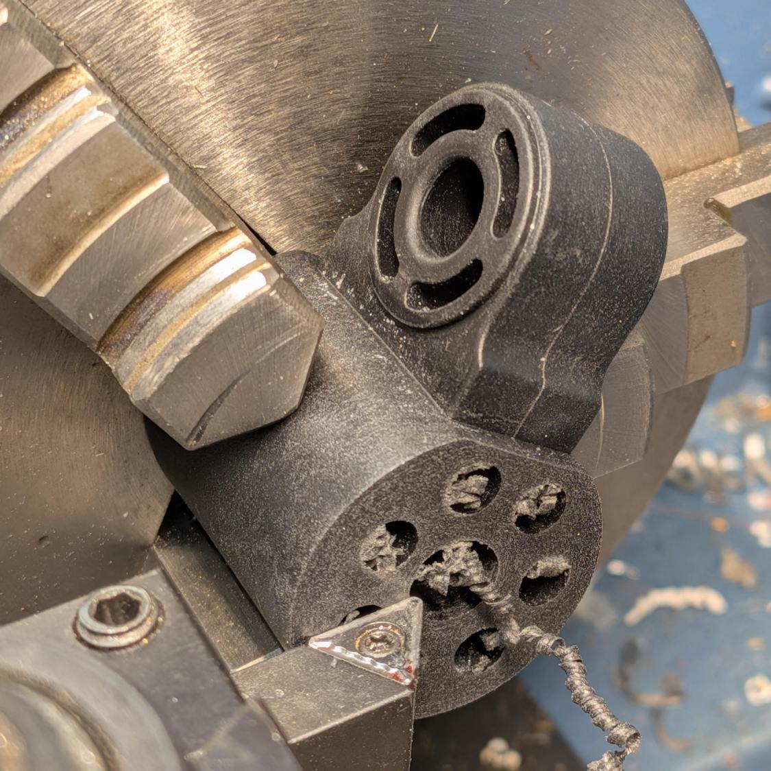
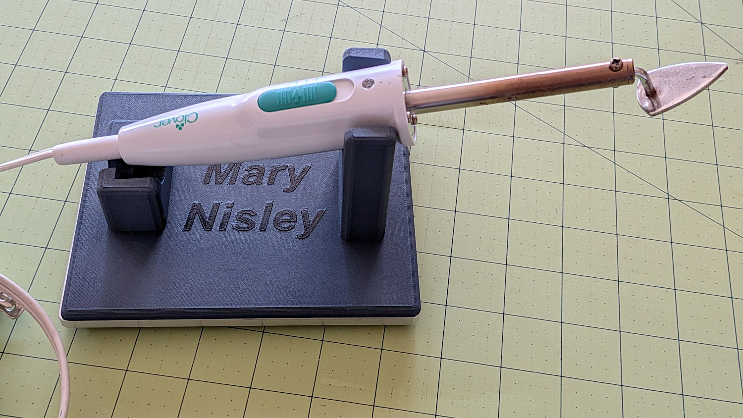
The alert reader will note the cord end isn’t quite snugged into its recess. In normal use, the cord hangs over the edge of the sewing table and pulls the iron into place.
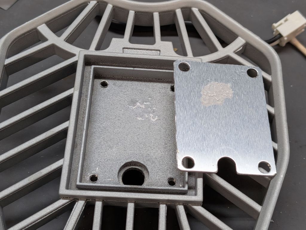
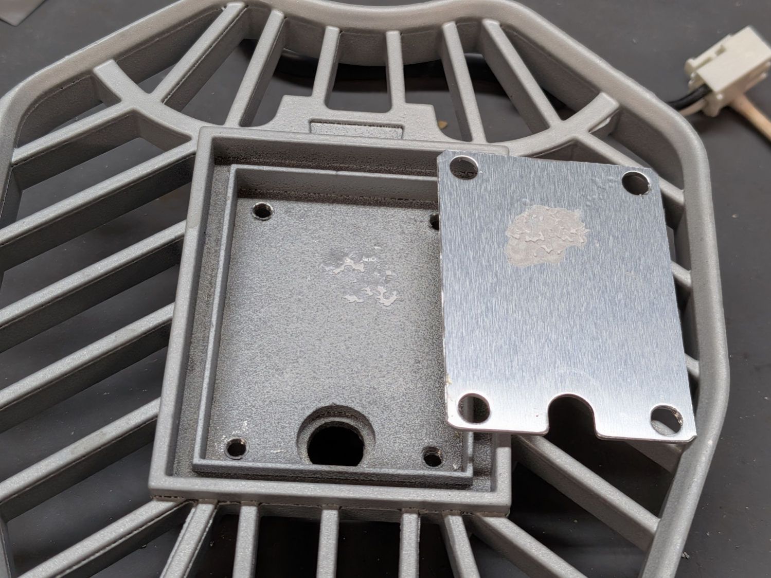
I embiggened the base to fit an aluminum plate from the stockpile, because that same cord tends to pull the holder around on the table. The plate puts enough weight on the silicone rubber feet to hold it firmly in place.
A layer of good double-stick tape strips bonds the aluminum plate to the PETG iron holder, after I once again discovered that craft adhesive sheets do not bond to PETG.