The Smell of Molten Projects in the Morning

Ed Nisley's Blog: Shop notes, electronics, firmware, machinery, 3D printing, laser cuttery, and curiosities. Contents: 100% human thinking, 0% AI slop.

Category: Machine Shop

Mechanical widgetry

  • MPCNC: Modified Drag Knife Adapter

    A trio of Cutter Cutting Plotter Blade Holders arrived:

    Collet pen holder
    Collet pen holder

    Despite the name, they’re not well-suited for drag knife blades, because they’re collets gripping a 2 mm shaft. The blade doesn’t rotate unless the plotter / cutter rotates the entire holder, which is actually a thing.

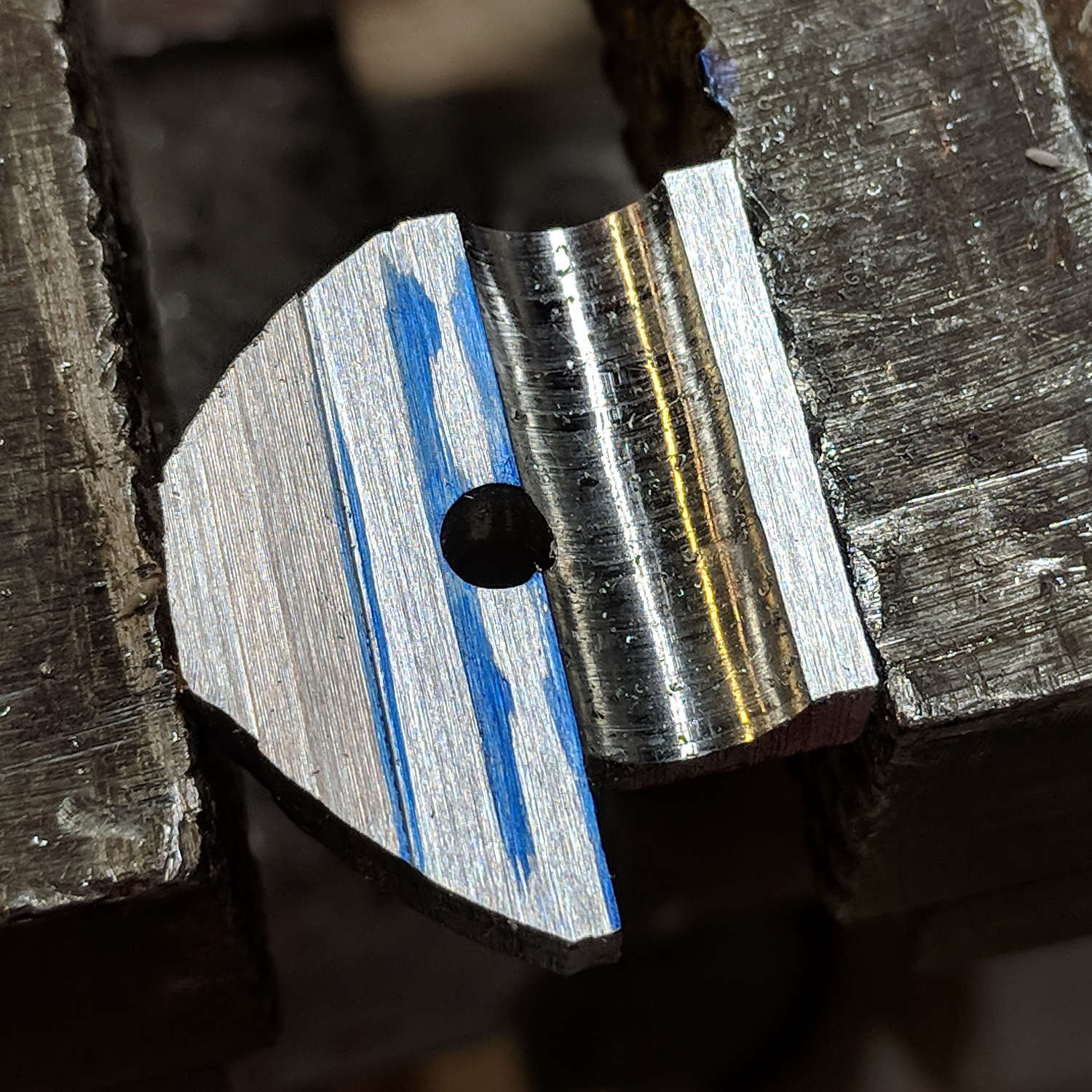
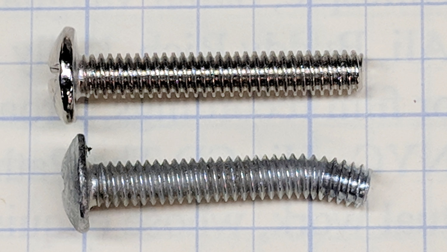
    I got ’em because the snout of a common ball-point pen refill measures about 2 mm:

    Collet pen holder - detail
    Collet pen holder – detail

    The glob around the tip comes from plotting too fast for conditions; about 1500 mm/min works better for continuous lines and 250 mm/min improves text.

    The stock MPCNC adapter has a single recess suited for Genuine Plotter Pens, but the knurled lock ring on these cheapies sticks out far enough to make them wobbly. This being an inconvenience up with which I need not put, a few lines of OpenSCAD tweak the stock STL:

    MPCNC knife adapter mods - OpenSCAD model
    MPCNC knife adapter mods – OpenSCAD model

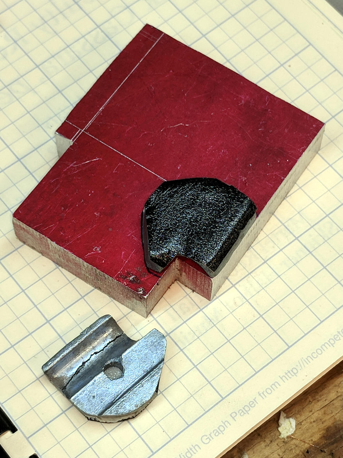
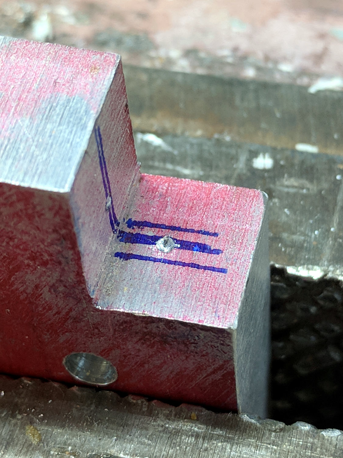
    The original STL is ivory, new cuts are cyan, and additions are reddish.

    The two support beams are now 1.6 mm = four thread widths, for improved slicing with a 0.35 mm nozzle and a higher spring constant.

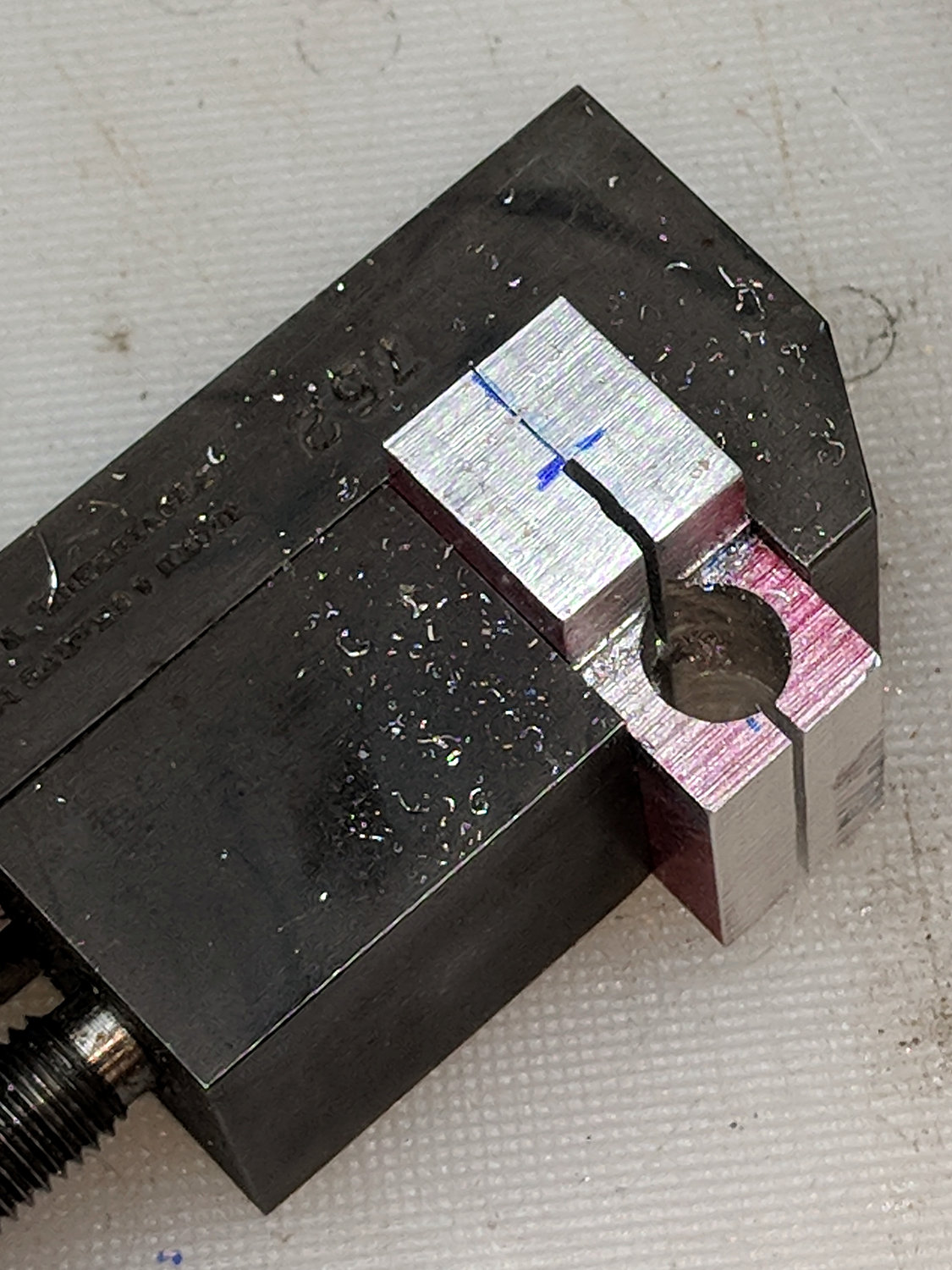
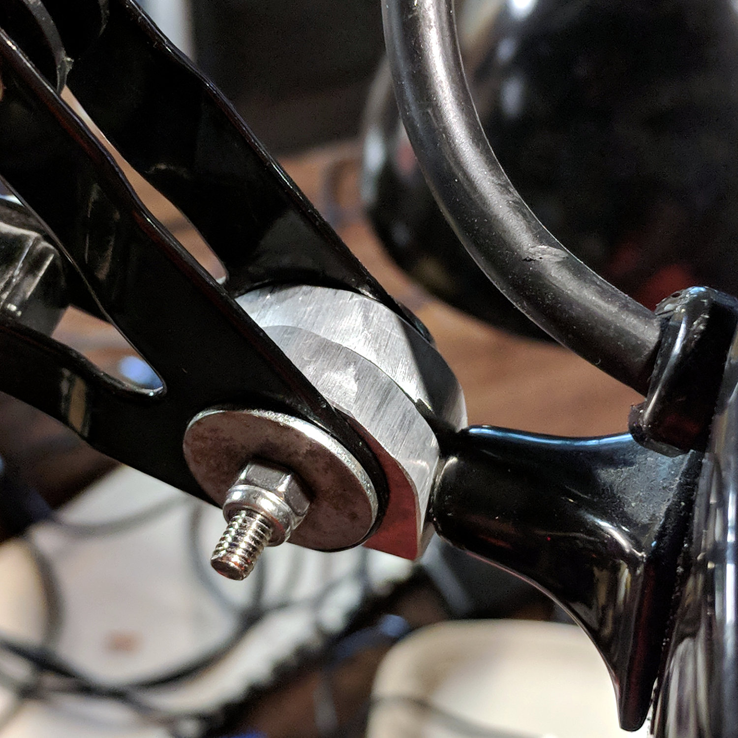
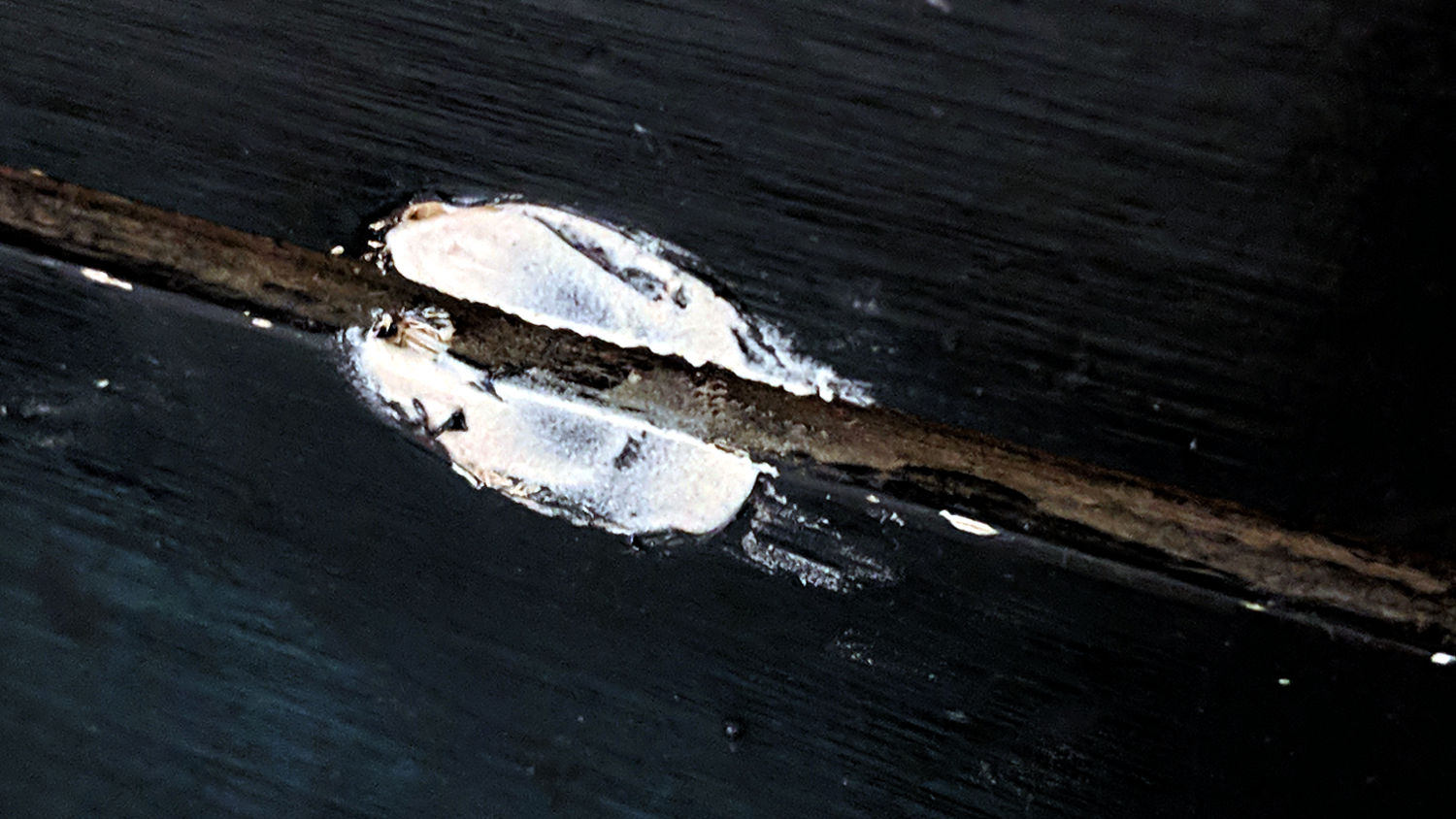
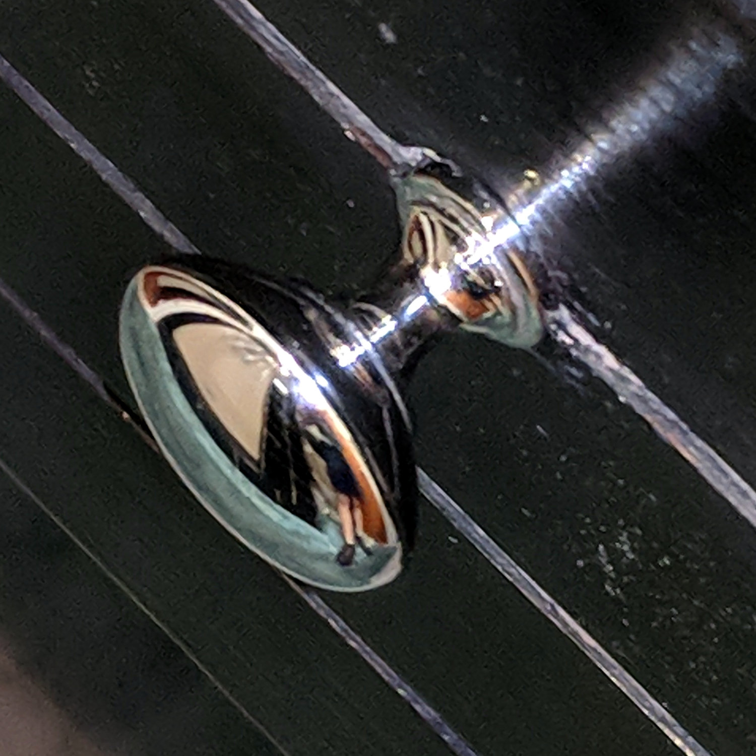
    It’s by-and-large indistinguishable from the old adapter:

    MPCNC - Pen Holder Detail
    MPCNC – Pen Holder Detail

    Which I was using upside-down, because the flange fit better.

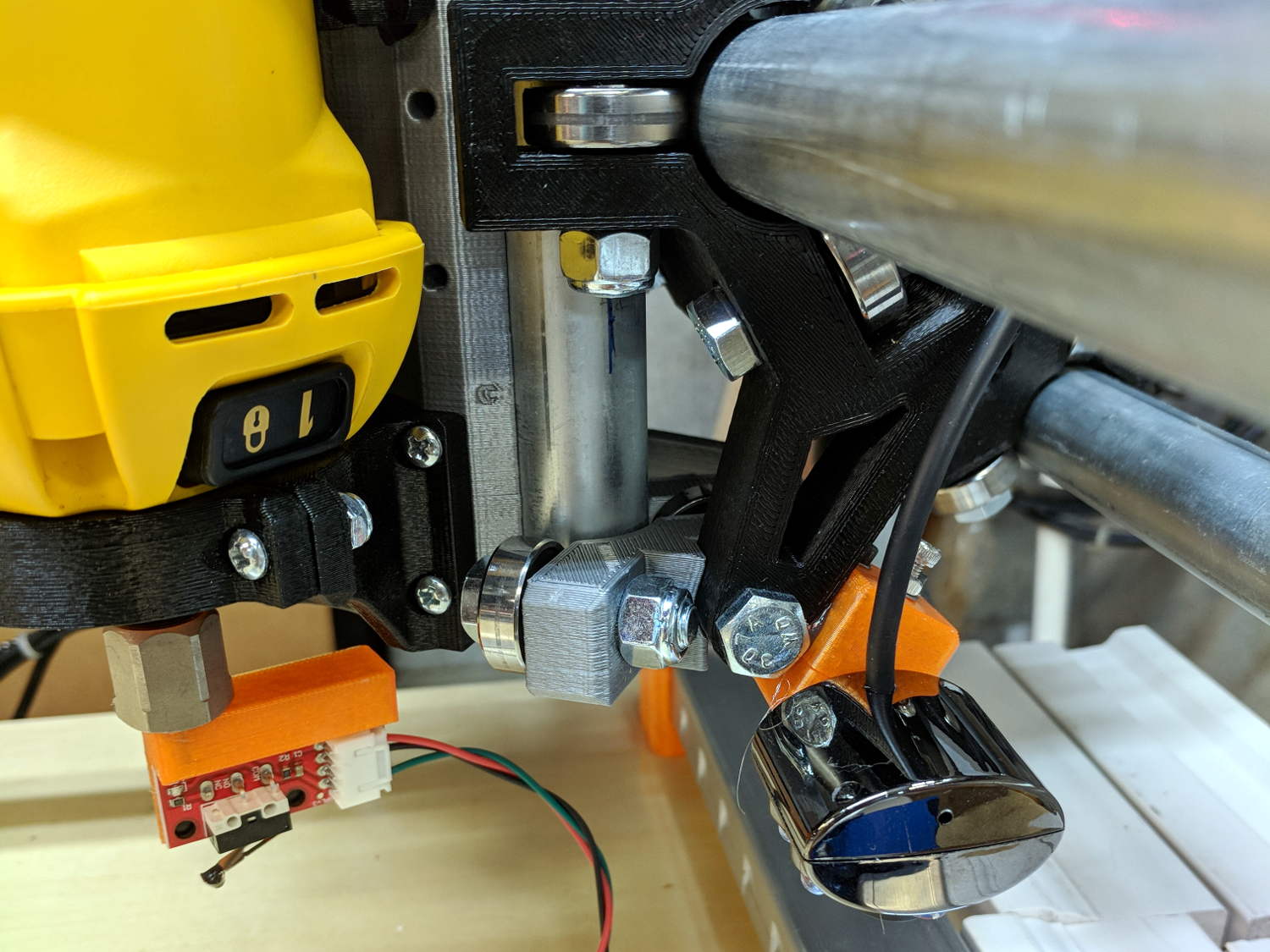
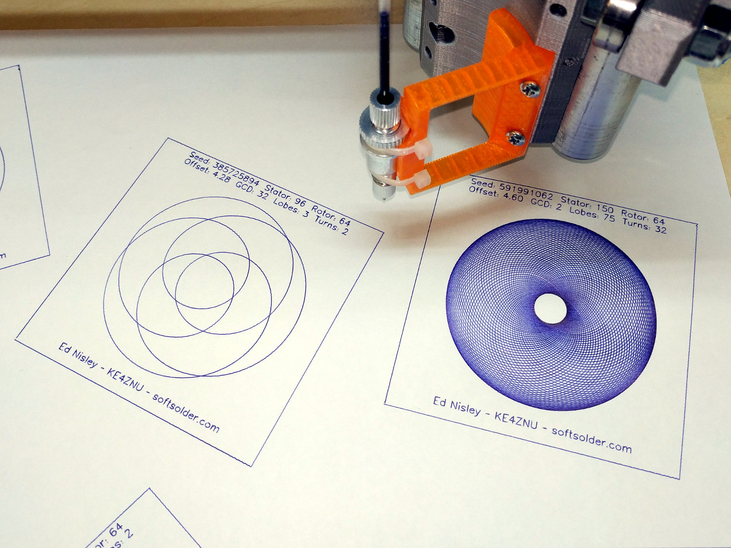
    The MPCNC works reasonably well as a pen plotter with a genuine ballpoint pen:

    MPCNC Ballpoint pen plots
    MPCNC Ballpoint pen plots

    The OpenSCAD source code as a GitHub Gist:

    // Adding clearance for eBay collet pen holder
    MPCNC_OD = 12.0; // pen holder OD (matches STL curvature)
    MPCNC_Z = 8.9; // Z offset of pen axis
    Pen_OD = 11.5; // actual pen body OD
    ID = 0;
    OD = 1;
    LENGTH = 2;
    Flange = [11.5,15.7,2.2]; // actual pen body flange
    Locknut = [16.0,16.0,2.8]; // knurled locknut
    Locknut_Offset = 4.5; // flange center to locknut
    Wall = [41.0,4 * 0.4,9.0]; // thicker walls for more spring and better fill
    $fn = 32; // default cylinder sides
    difference() {
    translate([-(101.3 + MPCNC_OD/2),-111.9,0]) // put pen axis above Y axis, flange centered on X axis
    import("/mnt/bulkdata/Project Files/Mostly Printed CNC/Accessories/Tool Holders/MPCNC_525_Drag_Knife-1860310.STL",
    convexity=5);
    if (true) // improve holder-to-mount fit if needed
    translate([0,60/2,8.90])
    rotate([90,0,0])
    cylinder(d=MPCNC_OD,h=60);
    translate([0,0,MPCNC_Z]) // improve flange slot clearance
    rotate([90,0,0])
    cylinder(d=Flange[OD] + 1.0,h=Flange[LENGTH] + 0.5,center=true);
    translate([0,Locknut_Offset – 0.5,MPCNC_Z]) // add locknut clearance
    rotate([-90,0,0])
    cylinder(d=Locknut[OD] + 1.5,h=Locknut[LENGTH] + 1.5,center=false);
    }
    # translate([-(27.0 + Wall.x/2),0,0]) { // embiggen walls for higher spring constant
    translate([0,-24.4,0])
    cube(Wall);
    translate([0,20.6 – Wall.y,0])
    cube(Wall);
    }
  • Halogen Desk Lamp Conversion: Preliminaries

    A discarded 20 W halogen desk lamp arrived in the Basement Laboratory for rebuilding:

    Halogen Desk Lamp - head layout
    Halogen Desk Lamp – head layout

    An incandescent bulb doesn’t care about AC or DC, so a simple transformer also serves as a counterweight in the base:

    Halogen Desk Lamp - 12 V 20 W transformer
    Halogen Desk Lamp – 12 V 20 W transformer

    I might replace it with some steel sheets, although I have no immediate need for a bare transformer.

    A case adds 19¢ to each 10 W 300 mA LED driver:

    Halogen Desk Lamp - 10 W LED driver innards
    Halogen Desk Lamp – 10 W LED driver innards

    Nice strain relief on those line-voltage wires, eh?

    A simple test setup with three 3 W COB LED panels:

    Halogen Desk Lamp - 3x3W COB LED test
    Halogen Desk Lamp – 3x3W COB LED test

    I clamped them to the aluminum sheet for heatsinking before I lit ’em up. The circles traced directly from the lamp’s hardware give some idea of the eventual layout.

    I have more-intense LEDs, but spreading the light over a larger area should work better for the intended purpose. These are pleasant warm-white LEDs, too.

    The fourth LED raised the forward voltage beyond the supply’s 42 V maximum, causing the supply to blink on and off.

    Much to my surprise, the driver has plenty of 60 Hz ripple:

    COB LED 3x3W - 10 W driver - 100 mA-div 10 V-div
    COB LED 3x3W – 10 W driver – 100 mA-div 10 V-div

    The top trace averages 280 mA and the bottom trace 32 V, so the LEDs run at 9 W = 3 W apiece, as they should.

    Now, for some metalworking …

  • Magnifying Desk Lamp Pivot Clamp Repair

    The clamp holding the magnifying lamp (with a fluorescent ring light!) over the Basement Laboratory Desk finally fractured:

    Magnifying Lamp Pivot - broken parts
    Magnifying Lamp Pivot – broken parts

    Gorilla Tape held the broken parts together well enough to determine how it used to work:

    Magnifying Lamp Pivot - hole sizing
    Magnifying Lamp Pivot – hole sizing

    The two parts used to be 11.2 mm thick, but it fit on a random chunk of half-inch aluminium plate so perfectly as to constitute a Good Omen:

    Magnifying Lamp Pivot - stock layout
    Magnifying Lamp Pivot – stock layout

    I decided the saw kerf would make up the difference, because, sheesh, we’re talking pot metal here.

    Lay out the center, use a transfer punch the same diameter as the lamp pivot to get the proper spacing, give it a whack:

    Magnifying Lamp Pivot - hole marking
    Magnifying Lamp Pivot – hole marking

    The alert reader will note I came that close to drilling the hole through the wrong side of the angle.

    And, yes, extrapolating the vertical edge downward suggests the large hole-to-be will intersect the small hole-in-being. This is deliberate: the clamp screw through the smaller hole fits into a recess around the lamp pivot shaft to keep it from sliding to-and-fro. I had to convince myself, but it really did work out OK.

    Pay some attention to clamping it at right angles to the spindle so the big hole goes through more-or-less in the right direction:

    Magnifying Lamp Pivot - drill press alignment
    Magnifying Lamp Pivot – drill press alignment

    The masking tape serves as a depth reminder:

    Magnifying Lamp Pivot - drilling
    Magnifying Lamp Pivot – drilling

    Set it up in a machinist’s clamp, bandsaw in twain, file the kerf reasonably flat, clamp the halves together, then bandsaw the clearance slot:

    Magnifying Lamp Pivot - clearance slot
    Magnifying Lamp Pivot – clearance slot

    The clearance kerf wasn’t nearly as on-center as I wanted, which doesn’t really matter, but I filed a bit more diligently on the shallow side while clearing up the slot:

    Magnifying Lamp Pivot - clearance filing
    Magnifying Lamp Pivot – clearance filing

    Introducing the new parts to Mr Disk Sander roundified them enough to pass inspection. These angular bits obviously require a bit more attention to detail:

    Magnifying Lamp Pivot - parts
    Magnifying Lamp Pivot – parts

    The lamp originally had a fancy knob on the screw which never worked particularly well, so I replaced it with a nylon locking nut to maintain a reasonable amount of pressure:

    Magnifying Lamp Pivot - installed
    Magnifying Lamp Pivot – installed

    The far end of the screw has a square shaft fitting into a square hole in the lamp arm, making it easy to torque the nut enough to make the pivot grip the shaft  properly; if I ever find my Belleville washer stash again, I’ll add one. I should cut the screw off, too, but that’s definitely in the nature of fine tuning.

    A pleasant morning of Quality Shop Time!

    The obligatory doodle with dimensions, some of which turned out to be completely incorrect:

    Magnifying Lamp Pivot - dimension doodles
    Magnifying Lamp Pivot – dimension doodles


  • Monthly Science: Cheese Slicer Epoxy vs. Water, Continuing

    The epoxy coating on our cheap aluminum (?) cheese slicer continues to corrode (clicky for more dots):

    Cheese slicer - epoxy failure - front
    Cheese slicer – epoxy failure – front

    The back side:

    Cheese slicer - epoxy failure - rear
    Cheese slicer – epoxy failure – rear

    The epoxy coating remains intact, although I expect it’ll break through as the corrosion products swell underneath.

    For whatever it’s worth, I applied the epoxy almost exactly one year ago.

  • Garden Hose Y-Valve Autopsy

    One of the handles snapped off a Y valve at the garden and I finally got around to an autopsy:

    Garden Y Valve - cross sectioned
    Garden Y Valve – cross sectioned

    That’s using a 24 tpi bandsaw blade, which doesn’t cut nearly as smoothly as a fancy diamond saw, but seems good enough for the purpose. Most of the ripply shading on the cut plane comes from specular reflections; it’s pot metal all the way through and cuts to a high shine.

    A closeup shows more detail around the (now hemispheric) ball valve:

    Garden Y Valve - thread detail
    Garden Y Valve – thread detail

    You can see faint straight lines just inside the hose threads, which gives a hint of what’s to come.

    Pry out the sectioned ball and dislodge the O-ring from the now-obvious insert:

    Garden Y Valve - O-rings
    Garden Y Valve – O-rings

    Gently squish the threads in the bench vise to pop out the insert:

    Garden Y Valve - plug removed
    Garden Y Valve – plug removed

    If lives depended on it, one could dismantle and repair the valve without recourse to a bandsaw, but …

  • MPCNC: Re-Relocated Probe Camera

    Although the camera doesn’t hit anything, it seemed entirely too exposed out in front:

    MPCNC - relocated camera - front view
    MPCNC – relocated camera – front view

    So I moved it to the back, where I can’t see it and maybe won’t clobber it:

    MPCNC Re-Relocated USB Camera
    MPCNC Re-Relocated USB Camera

    The camera sensor is now almost exactly aligned with the XY axes, so the goofy rotation is gone and the offsets look better:

    bCNC - Rear-mount Camera Probe Config
    bCNC – Rear-mount Camera Probe Config

    The size of the “10 mm” inner circle at the crosshair depends on the target distance, so it’ll be smaller for surfaces clamped onto and thus rising above the table. Depending on how much that matters, I can tweak the camera focus and scale factor to make the answer come out right.

    The setup at the home position looked like this from a different perspective:

    MPCNC - Rear-mounted USB Camera
    MPCNC – Rear-mounted USB Camera

    No operational change, just a cleanup.

  • Bathroom Drawer Knob: Whoopsie!

    I managed to snag a cargo pocket on the under-sink drawer knob in the Black Bathroom:

    Bathroom knob - bent screw
    Bathroom knob – bent screw

    Did a job on the pocket, too, although after Mary was done with it, you’d never know.

    With that much of a bend in the screw, the knob left a nasty divot in the drawer front requiring a layer of wood-filled epoxy:

    Bathroom knob - filled divot
    Bathroom knob – filled divot

    I sanded it more-or-less flush with the surface, taking great pains to not scuff the surrounding paint. A similar layer fills the corresponding divot under the screw head inside the front.

    Despite appearances, only about 1/8 inch of the epoxy peeked around the knob, so I painted it black with a Sharpie, ran the knob onto the screw, and declared victory:

    Bathroom knob - restored
    Bathroom knob – restored

    I’ll (try to) (remember to) stand further back from the knob …