|
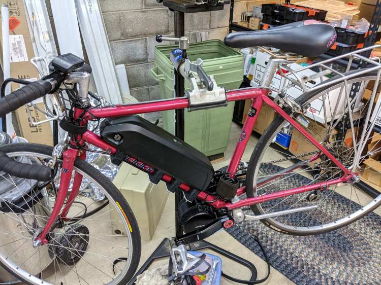
// Terry Symmetry – Bafang e-bike conversion |
|
// Ed Nisley KE4ZNU 2021-06 |
|
|
|
Layout = "BuildClip"; // [Frame,Block,AllBlocks,BuildBlock,DispMount,BrakeMagnet,ShiftCap,BuildShiftCap,Case,NutMold,HeadClip, BuildClip] |
|
|
|
Station = 4; // [0:4] |
|
|
|
Support = false; |
|
|
|
//- Extrusion parameters must match reality! |
|
|
|
/* [Hidden] */ |
|
|
|
ThreadThick = 0.25; |
|
ThreadWidth = 0.40; |
|
|
|
HoleWindage = 0.2; |
|
|
|
Protrusion = 0.1; // make holes end cleanly |
|
|
|
inch = 25.4; |
|
|
|
function IntegerMultiple(Size,Unit) = Unit * ceil(Size / Unit); |
|
|
|
ID = 0; |
|
OD = 1; |
|
LENGTH = 2; |
|
|
|
|
|
//———- |
|
// Dimensions |
|
// Bike frame lies along X axis, rear to +X |
|
|
|
FrameTube = [400,28.9 + HoleWindage,28.9 + HoleWindage]; // X = longer than anything else |
|
|
|
FrameSides = 24; |
|
|
|
SpeedOD = 3.5; // speed sensor cable |
|
PowerOD = 6.7; // power cable |
|
Harness = [6.0,13.0,30.0]; // main motor-to-handlebar cable |
|
GearOD = 3.0; // gear sensor cable |
|
|
|
HandlebarMax = 1*inch; // middle handlebar diameter |
|
HandlebarMin = 24.0; // .. tape section |
|
|
|
HeadTube = [32.0,35.0,8.0]; // ID=tube OD=lug LENGTH=clear between lugs |
|
|
|
BottleStud = [5.0,10.0,IntegerMultiple(1.2,ThreadThick)]; // frame fitting for bottle screws |
|
|
|
BafangClampID = 22.3; // their handlebar clamp diameter |
|
|
|
ShiftOD = 2.0; // rear shifter cable |
|
ShiftFerrule = [ShiftOD,6.0,10.0]; |
|
ShiftOffset = 7.5; // .. from downtube |
|
ShiftAngle = -20; // .. from midline |
|
|
|
BatteryBoss = [5.5,16.0,2.5]; // battery mount boss, center boss is round |
|
BossSlotOAL = 32.0; // .. end bosses are elongated |
|
BossOC = 65.0; // .. along length of mount |
|
|
|
LatchWidth = 10.0; // battery latches to mount plate |
|
LatchThick = 1.5; |
|
LatchOC = 56.0; |
|
|
|
// Per-block features |
|
// first element is unadorned block |
|
|
|
Latches = [false,true,true,false,false]; // clearance for battery latch clips |
|
Notch = [false,true,true,false,false]; // notch for battery screw pockets |
|
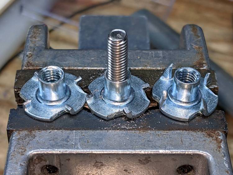
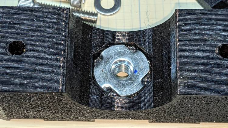
Recess = ["None","TeeNut","Bottle","Bottle","TeeNut"]; // stud or nut clearance against frame |
|
|
|
HarnessCable = [false,true,true,true,true]; // passage for main harness cable |
|
|
|
ShiftWire = [false,true,true,true,true]; // .. shifter wire through sensor |
|
Ferrules = ["None","Both","Front","None","Back"]; // ferrule and bushing ssockets |
|
|
|
GearCable = [false,false,true,true,true]; // .. gear sensor cable |
|
|
|
// M3 SHCS nyloc nut |
|
Screw3 = [3.0,5.5,35.0]; // OD, LENGTH = head |
|
Washer3 = [3.7,7.0,0.7]; |
|
Nut3 = [3.0,6.0,4.0]; |
|
|
|
// M4 SHCS nyloc nut |
|
Screw4 = [4.0,7.0,4.0]; // OD, LENGTH = head |
|
Washer4 = [4.2,8.9,1.0]; |
|
Nut4 = [4.0,7.8,5.0]; |
|
|
|
|
|
// M5 SHCS nyloc nut |
|
Screw5 = [5.0,8.5,5.0]; // OD, LENGTH = head |
|
Washer5 = [5.5,10.1,1.0]; |
|
Nut5 = [5.0,9.0,5.0]; |
|
Teenut5 = [6.5,17.0,8.0,2.0]; // OD, LENGTH+1 = flange |
|
|
|
// 10-32 Philips nyloc nut |
|
Screw10 = [5.2,9.8,3.6]; // OD, LENGTH = head |
|
Washer10 = [5.5,11.0,1.0]; |
|
Nut10 = [5.2,10.7,6.2]; |
|
|
|
CableTie = [150,5.0,2.0]; |
|
|
|
WallThick = 4.0; // thinnest wall |
|
|
|
BlockMinZ = -(FrameTube.z/2 + WallThick); |
|
BlockMaxZ = FrameTube.z/2 + max(WallThick,Teenut5[LENGTH]) + BatteryBoss[LENGTH]; |
|
|
|
Block = [25.0,78.0,BlockMaxZ – BlockMinZ]; // Y = battery width |
|
echo(str("Block: ",Block)); |
|
|
|
Kerf = 0.5; // cut through middle to apply compression |
|
|
|
CornerRadius = 5.0; |
|
|
|
EmbossDepth = 2*ThreadThick; // lettering depth |
|
|
|
//———————- |
|
// Useful routines |
|
|
|
module PolyCyl(Dia,Height,ForceSides=0) { // based on nophead's polyholes |
|
Sides = (ForceSides != 0) ? ForceSides : (ceil(Dia) + 2); |
|
FixDia = Dia / cos(180/Sides); |
|
cylinder(d=(FixDia + HoleWindage),h=Height,$fn=Sides); |
|
} |
|
|
|
|
|
|
|
// frame downtube |
|
|
|
module Frame() { |
|
|
|
rotate([0,90,0]) rotate(180/FrameSides) |
|
cylinder(d=FrameTube.z,h=FrameTube.x,center=true,$fn=FrameSides); |
|
} |
|
|
|
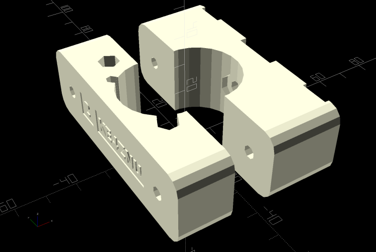
// clamp overall shape |
|
|
|
module ClampBlock(BlkNum = 1) { |
|
|
|
Screw = Screw4; |
|
Washer = Washer4; |
|
Nut = Nut4; |
|
|
|
ScrewOC = LatchOC; |
|
|
|
ScrewSides = 8; |
|
ScrewOrient = 180/ScrewSides; |
|
|
|
ScrewRecess = LatchThick + Screw[LENGTH] + Washer[LENGTH] + 1.0; |
|
echo(str("Screw length: ",Block.z – ScrewRecess)); |
|
|
|
difference() { |
|
hull() |
|
for (i=[-1,1], j=[-1,1]) |
|
translate([i*(Block.x/2 – CornerRadius),j*(Block.y/2 – CornerRadius),BlockMinZ]) |
|
cylinder(r=CornerRadius,h=Block.z,$fn=4*3); |
|
|
|
cube([2*Block.x,2*Block.y,Kerf],center=true); |
|
|
|
Frame(); |
|
|
|
for (j=[-1,1]) { |
|
translate([0,j*ScrewOC/2,BlockMinZ – Protrusion]) |
|
rotate(ScrewOrient) |
|
PolyCyl(Screw[ID],2*Block.z,ScrewSides); |
|
translate([0,j*ScrewOC/2,BlockMaxZ – ScrewRecess]) |
|
rotate(ScrewOrient) |
|
PolyCyl(Washer[OD],BlockMaxZ,ScrewSides); |
|
} |
|
|
|
if (Latches[BlkNum]) |
|
for (i=[-1,1]) |
|
translate([0,i*LatchOC/2,BlockMaxZ – LatchThick/2 + Protrusion]) |
|
cube([BossSlotOAL,LatchWidth,LatchThick + Protrusion],center=true); |
|
|
|
if (Notch[BlkNum]) |
|
translate([0,0,BlockMaxZ – BatteryBoss[LENGTH]/2 + Protrusion]) |
|
cube([BossSlotOAL,BatteryBoss[OD],BatteryBoss[LENGTH] + Protrusion],center=true); |
|
|
|
if (HarnessCable[BlkNum]) |
|
rotate([-155,0,0]) { |
|
translate([0,FrameTube.y/2 – Harness[ID]/2,0]) |
|
cube([2*Block.x,2*Harness[ID],Harness[ID]],center=true); |
|
translate([0,FrameTube.y/2 + Harness[ID]/2,0]) |
|
rotate([0,90,0]) |
|
translate([0,0,-Block.x]) |
|
rotate(180/6) |
|
PolyCyl(Harness[ID],2*Block.x,6); |
|
} |
|
|
|
if (GearCable[BlkNum]) |
|
rotate([-45,0,0]) { |
|
translate([0,FrameTube.y/2 – GearOD/2,0]) |
|
cube([2*Block.x,2*GearOD,GearOD],center=true); |
|
translate([0,FrameTube.y/2 + GearOD/2,0]) |
|
rotate([0,90,0]) |
|
translate([0,0,-Block.x]) |
|
rotate(180/6) |
|
PolyCyl(GearOD,2*Block.x,6); |
|
} |
|
|
|
rotate([ShiftAngle,0,0]) { |
|
if (ShiftWire[BlkNum]) |
|
translate([-Block.x,FrameTube.y/2 + ShiftOffset,0]) |
|
rotate([0,90,0]) rotate(-(90 + ShiftAngle)) |
|
PolyCyl(ShiftOD,2*Block.x,6); |
|
|
|
if (Ferrules[BlkNum] == "Back" || Ferrules[BlkNum] == "Both") { |
|
i = 1; |
|
translate([i*(Block.x/2 – ShiftFerrule[LENGTH]),FrameTube.y/2 + ShiftOffset,0]) |
|
rotate([0,i*90,0]) rotate(-i*(90 + ShiftAngle)) |
|
PolyCyl(ShiftFerrule[OD],Block.x,6); |
|
} |
|
|
|
if (Ferrules[BlkNum] == "Front" || Ferrules[BlkNum] == "Both") { |
|
i = -1; |
|
translate([i*(Block.x/2 – ShiftFerrule[LENGTH]),FrameTube.y/2 + ShiftOffset,0]) |
|
rotate([0,i*90,0]) rotate(-i*(90 + ShiftAngle)) |
|
PolyCyl(ShiftFerrule[OD],Block.x,6); |
|
} |
|
} |
|
|
|
if (Recess[BlkNum] == "Bottle") { |
|
rotate(ScrewOrient) { |
|
PolyCyl(BottleStud[ID],2*Block.z,ScrewSides); |
|
PolyCyl(BottleStud[OD],FrameTube.z/2 + BottleStud[LENGTH],ScrewSides); |
|
} |
|
} |
|
else if (Recess[BlkNum] == "TeeNut") { |
|
rotate(ScrewOrient) { |
|
PolyCyl(Teenut5[ID],2*Block.z,ScrewSides); |
|
PolyCyl(Teenut5[OD],FrameTube.z/2 + Teenut5[LENGTH+1],ScrewSides); |
|
} |
|
} |
|
|
|
translate([0,15,BlockMaxZ – EmbossDepth/2 + Protrusion]) |
|
cube([9.0,8,EmbossDepth],center=true); |
|
|
|
translate([0,17,BlockMinZ + EmbossDepth/2 – Protrusion]) |
|
cube([9.0,8,EmbossDepth],center=true); |
|
translate([0,-5,BlockMinZ + EmbossDepth/2 – Protrusion]) |
|
cube([9.0,30,EmbossDepth],center=true); |
|
|
|
} |
|
|
|
translate([0,15,BlockMaxZ – EmbossDepth]) |
|
linear_extrude(height=EmbossDepth) |
|
rotate(90) |
|
text(text=str(BlkNum),size=5,spacing=1.00,font="Bitstream Vera Sans:style=Bold", |
|
halign="center",valign="center"); |
|
|
|
translate([0,17,BlockMinZ]) |
|
linear_extrude(height=EmbossDepth) |
|
rotate(-90) mirror([0,1,0]) |
|
text(text=str(BlkNum),size=4.5,spacing=1.00,font="Bitstream Vera Sans:style=Bold", |
|
halign="center",valign="center"); |
|
|
|
translate([0,-5,BlockMinZ]) |
|
linear_extrude(height=EmbossDepth) |
|
rotate(-90) mirror([0,1,0]) |
|
text(text="KE4ZNU",size=4.5,spacing=1.00,font="Bitstream Vera Sans:style=Bold", |
|
halign="center",valign="center"); |
|
} |
|
|
|
// complete clamp block |
|
|
|
module Clamp(BlkNum = 1) { |
|
|
|
ClampBlock(BlkNum); |
|
|
|
if (Support) |
|
color("Yellow") { |
|
NumRibs = 7; |
|
RibOC = Block.x/(NumRibs – 1); |
|
intersection() { |
|
translate([0,0,BlockMaxZ + Kerf/2]) |
|
cube([2*Block.x,2*Block.y,Block.z],center=true); |
|
union() { |
|
translate([0,0,Kerf/2]) |
|
cube([1.1*Block.x,FrameTube.y – 2*ThreadThick,4*ThreadThick],center=true); |
|
for (i=[-floor(NumRibs/2):floor(NumRibs/2)]) |
|
translate([i*RibOC,0,0]) |
|
rotate([0,90,0]) rotate(180/FrameSides) |
|
cylinder(d=FrameTube.z – 2*ThreadThick,h=2*ThreadWidth,$fn=FrameSides,center=true); |
|
/* |
|
translate([0,FrameTube.y/2 + PowerOD/2,Kerf/2]) |
|
cube([1.1*Block.x,PowerOD – 2*ThreadWidth,4*ThreadThick],center=true); |
|
for (i=[-floor(NumRibs/2):floor(NumRibs/2)]) |
|
translate([i*RibOC,FrameTube.y/2 + PowerOD/2,PowerOD/4]) |
|
cube([2*ThreadWidth,PowerOD – 2*ThreadWidth,PowerOD/2 – 2*ThreadThick],center=true); |
|
|
|
translate([0,-(FrameTube.y/2 + SpeedOD/2),Kerf/2]) |
|
cube([1.1*Block.x,SpeedOD – 2*ThreadWidth,4*ThreadThick],center=true); |
|
for (i=[-floor(NumRibs/2):floor(NumRibs/2)]) |
|
translate([i*RibOC,-(FrameTube.y/2 + SpeedOD/2),SpeedOD/4]) |
|
cube([2*ThreadWidth,SpeedOD – 2*ThreadWidth,SpeedOD/2 – 2*ThreadThick],center=true); |
|
*/ |
|
} |
|
} |
|
} |
|
} |
|
|
|
// Half clamp sections for printing |
|
|
|
module HalfClamp(BlkNum = 1, Section = "Upper") { |
|
|
|
render() |
|
if (Section == "Upper") |
|
intersection() { |
|
translate([0,0,BlockMaxZ/2]) |
|
cube([1.1*Block.x,Block.y,BlockMaxZ],center=true); |
|
translate([0,0,-Kerf/2]) |
|
Clamp(BlkNum); |
|
} |
|
else |
|
intersection() { |
|
translate([0,0,-BlockMinZ/2]) |
|
cube([1.1*Block.x,Block.y,-BlockMinZ],center=true); |
|
translate([0,0,-BlockMinZ]) |
|
Clamp(BlkNum); |
|
} |
|
} |
|
|
|
// Handlebar mount for controller |
|
|
|
module DispMount() { |
|
|
|
ClampRing = [HandlebarMax,HandlebarMax + 2*WallThick,10.0]; |
|
ClampOffset = (HandlebarMax + BafangClampID)/2 + 6.0; |
|
|
|
DispStudLenth = 16.5; |
|
|
|
NumSides = 24; |
|
|
|
Tilt = 0*atan2((ClampRing[OD] – BafangClampID)/2,ClampOffset); |
|
echo(str("Tilt: ",Tilt)); |
|
|
|
difference() { |
|
union() { |
|
hull() { |
|
cylinder(d=ClampRing[OD],h=ClampRing[LENGTH],$fn=NumSides); |
|
translate([0,ClampOffset,0]) |
|
cylinder(d=BafangClampID,h=ClampRing[LENGTH],$fn=NumSides); |
|
} |
|
translate([0,ClampOffset,0]) |
|
cylinder(d=BafangClampID,h=ClampRing[LENGTH] + DispStudLenth,$fn=NumSides); |
|
translate([-ClampRing[ID]/4,-(ClampRing[OD]/2),ClampRing[LENGTH]/2]) |
|
rotate([0,90,0]) rotate(180/8) |
|
cylinder(d=ClampRing[LENGTH]/cos(180/8),h=ClampRing[ID]/2,$fn=8); |
|
} |
|
cube([Kerf,4*ClampOffset,4*DispStudLenth],center=true); |
|
translate([0,0,-Protrusion]) |
|
cylinder(d=ClampRing[ID],h=ClampRing[LENGTH] + 2*Protrusion,$fn=NumSides); |
|
translate([-ClampRing[ID]/2,-(ClampRing[OD]/2),ClampRing[LENGTH]/2]) |
|
rotate([0,90,0]) rotate(180/8) |
|
PolyCyl(Screw3[ID],ClampRing[ID],8); |
|
for (i=[-1,1]) |
|
translate([i*ClampRing[ID]/4,-(ClampRing[OD]/2),ClampRing[LENGTH]/2]) |
|
rotate([0,i*90,0]) rotate(180/8) |
|
PolyCyl(Washer3[OD],ClampRing[ID],$fn=8); |
|
|
|
translate([-5,25,EmbossDepth/2 – Protrusion/2]) |
|
rotate(Tilt) |
|
cube([4.5,21.5,EmbossDepth + Protrusion],center=true); |
|
|
|
if (false) |
|
translate([-6,25,EmbossDepth/2 – Protrusion/2]) |
|
rotate(-Tilt) |
|
cube([4.0,27,EmbossDepth + Protrusion],center=true); |
|
|
|
} |
|
|
|
translate([-5,25,0]) |
|
linear_extrude(height=EmbossDepth) |
|
rotate(90 + Tilt) mirror([0,1,0]) |
|
text(text="KE4ZNU",size=3.3,spacing=1.05,font="Bitstream Vera Sans:style=Bold", |
|
halign="center",valign="center"); |
|
|
|
if (false) |
|
translate([-6,25,0]) |
|
linear_extrude(height=EmbossDepth) |
|
rotate(90 – Tilt) mirror([0,1,0]) |
|
text(text="softsolder.com",size=2.2,spacing=1.05,font="Bitstream Vera Sans:style=Bold", |
|
halign="center",valign="center"); |
|
|
|
} |
|
|
|
|
|
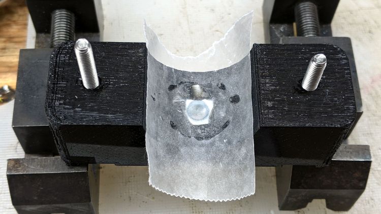
// Mold to reshape speed sensor nut |
|
|
|
SensorNut = [0,14.4,13.0]; |
|
SensorMold = [SensorNut[OD] + 2*WallThick,SensorNut[OD] + 2*WallThick,SensorNut[LENGTH] + WallThick]; |
|
MoldSides = 20; |
|
RodOD = 1.6; |
|
|
|
module NutMoldBlock() { |
|
|
|
difference() { |
|
|
|
translate([0,0,SensorMold.z/2]) |
|
cube(SensorMold,center=true); |
|
|
|
translate([0,0,WallThick]) |
|
rotate(180/MoldSides) |
|
PolyCyl(SensorNut[OD],2*SensorNut[LENGTH],MoldSides); |
|
translate([0,0,-Protrusion]) |
|
rotate(180/8) |
|
PolyCyl(SpeedOD,2*SensorMold.z,8); |
|
|
|
for (i=[-1,1]) |
|
translate([i*(SensorMold.x/2 – WallThick/2),SensorMold.y,SensorMold.z/2]) |
|
rotate([90,0,0]) |
|
PolyCyl(RodOD,2*SensorMold.y,6); |
|
} |
|
} |
|
|
|
module NutMold() { |
|
gap = 1.0; |
|
|
|
for (j=[-1,1]) |
|
translate([0,j*gap,0]) |
|
intersection() { |
|
translate([0,j*SensorMold.y,0]) |
|
cube(2*SensorMold,center=true); |
|
NutMoldBlock(); |
|
} |
|
} |
|
|
|
|
|
// Brake sensor magnet mount |
|
// Magnetized through thinnest section |
|
|
|
module BrakeMagnet() { |
|
|
|
Magnet = [10.5,3.0,5.5]; |
|
Plate = 2*ThreadThick; |
|
BrakeRad = 10.0; // brake handle curve Radius |
|
Holder = [2*BrakeRad,7.0,Magnet.z + Plate]; |
|
|
|
|
|
difference() { |
|
intersection() { |
|
translate([0,-BrakeRad,0]) |
|
rotate(180/24) |
|
cylinder(r=BrakeRad,h=Holder.z,$fn=24); |
|
translate([0,BrakeRad – Holder.y,Holder.z/2]) |
|
cube([2*BrakeRad,2*BrakeRad,Holder.z],center=true); |
|
translate([0,0,-2*BrakeRad/sqrt(2) + Holder.z – 3.0 + BrakeRad]) |
|
rotate([0,45,0]) |
|
cube(2*[BrakeRad,2*BrakeRad,BrakeRad],center=true); |
|
} |
|
translate([0,Magnet.y/2 – Holder.y – Protrusion/2,Magnet.z/2 + Plate + Protrusion/2]) |
|
cube(Magnet + [0,Protrusion,Protrusion],center=true); |
|
} |
|
|
|
} |
|
|
|
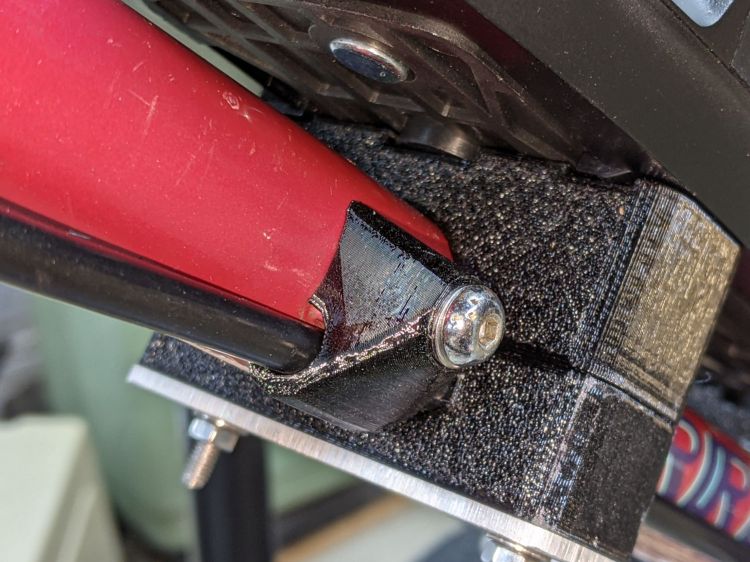
// Shift stud cap |
|
// With passage for harness cable |
|
|
|
CapBlock = [18,18,16.5]; |
|
|
|
module ShiftCap() { |
|
|
|
Rounding = 3.5; |
|
CapM = 3.0; |
|
StudBase = [12.5,12.5,4.5]; |
|
Stud = [5.0,9.3,15.5]; |
|
|
|
difference() { |
|
hull() { |
|
translate([0,0,CapBlock.z – 0.5]) |
|
PolyCyl(Washer5[OD],0.5,12); |
|
for (i=[-1,1], j=[-1,1]) |
|
translate([i*(CapBlock.x/2 – Rounding),j*(CapBlock.y/2 – Rounding),0]) |
|
sphere(r=Rounding,$fn=12); |
|
translate([-CapBlock.x/2,-Harness[ID]/2 – StudBase.y/2,StudBase.z/2]) |
|
rotate([0,90,0]) |
|
cylinder(d=Harness[ID] + 2*WallThick,h=CapBlock.x,$fn=12); |
|
} |
|
|
|
translate([0,0,-(FrameTube.z/2 – CapM)]) |
|
Frame(); |
|
|
|
PolyCyl(Screw5[ID],2*CapBlock.z,6); |
|
|
|
PolyCyl(Stud[OD],Stud[LENGTH],12); |
|
|
|
translate([0,0,StudBase.z/2]) |
|
cube(StudBase,center=true); |
|
|
|
translate([0,-StudBase.y/2,StudBase.z/2]) |
|
cube(StudBase + [0,-StudBase.y/2,0],center=true); |
|
|
|
translate([-CapBlock.x,-Harness[ID]/2 – StudBase.y/2,StudBase.z/2]) |
|
rotate([0,90,0]) |
|
cylinder(d=1.5*Harness[ID],h=2*CapBlock.x,$fn=12); |
|
|
|
} |
|
} |
|
|
|
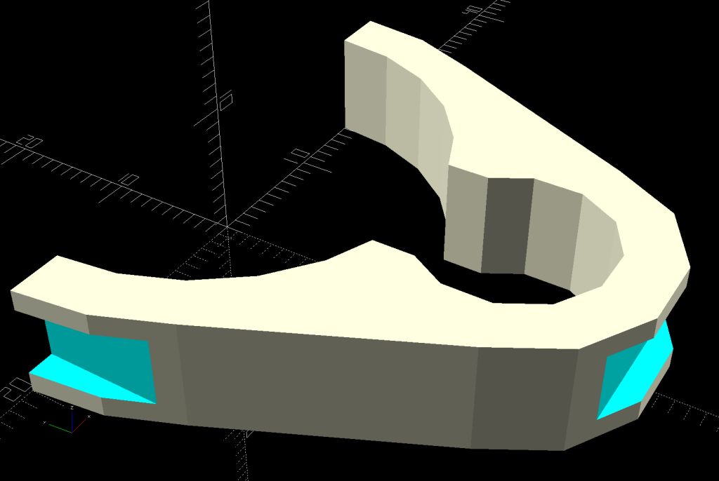
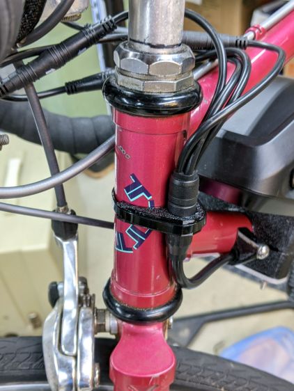
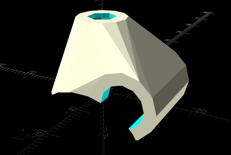
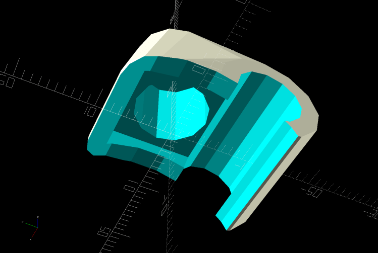
// Head tube clip for harness cable joint |
|
|
|
module HeadClip() { |
|
|
|
CableOD = Harness[OD]; |
|
|
|
difference() { |
|
linear_extrude(height=HeadTube[LENGTH],convexity=10) |
|
difference() { |
|
hull() { |
|
circle(d=HeadTube[ID] + 2*WallThick,$fn=FrameSides); |
|
translate([0,-(HeadTube[ID] + CableOD)/2]) |
|
rotate(180/(FrameSides/2)) |
|
circle(d=CableOD + 2*WallThick,$fn=FrameSides/2); |
|
} |
|
circle(d=HeadTube[ID] + HoleWindage,$fn=FrameSides); |
|
translate([0,-(HeadTube[ID] + CableOD)/2]) |
|
rotate(180/(FrameSides/2)) |
|
circle(d=CableOD + HoleWindage,$fn=FrameSides/2); |
|
translate([0,-HeadTube[ID]/2]) |
|
square(0.75*CableOD,center=true); |
|
translate([0,HeadTube[ID]]) |
|
square(2*HeadTube[ID],center=true); |
|
} |
|
translate([0,-(HeadTube[ID]/2 + CableOD + WallThick – CableTie.z/2),HeadTube[LENGTH]/2]) |
|
cube([HeadTube[ID],CableTie.z,CableTie.y],center=true); |
|
|
|
for (i=[-1,1]) |
|
translate([i*(HeadTube[ID]/2 + WallThick – CableTie.z/2),0,HeadTube[LENGTH]/2]) |
|
cube([CableTie.z,HeadTube[ID],CableTie.y],center=true); |
|
} |
|
} |
|
|
|
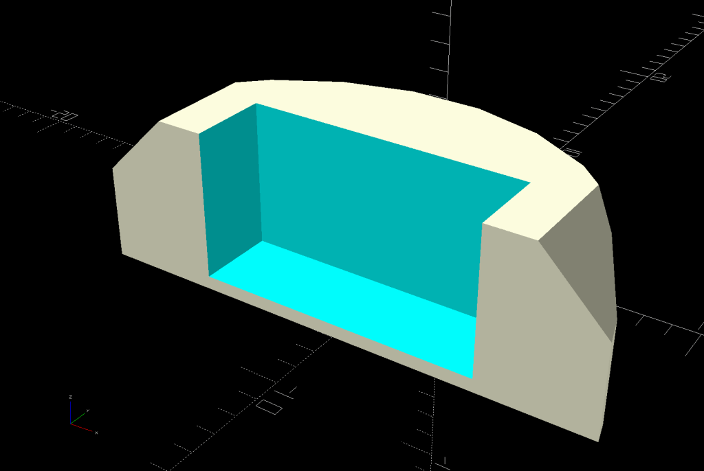
// Programming cable case |
|
|
|
ProgCavity = [60.0,18.0,7.0]; |
|
ProgBlock = [70.0,24.0,13.0]; |
|
ProgCableOD = 4.0; |
|
|
|
module ProgrammerCase() { |
|
|
|
difference() { |
|
hull() { |
|
for (i=[-1,1], j=[-1,1]) |
|
translate([i*(ProgBlock.x/2 – CornerRadius),j*i*(ProgBlock.y/2 – CornerRadius),-ProgBlock.z/2]) |
|
cylinder(r=CornerRadius,h=ProgBlock.z,$fn=12); |
|
} |
|
translate([-ProgBlock.x,0,0]) |
|
rotate([0,90,0]) |
|
PolyCyl(ProgCableOD,3*ProgBlock.x,6); |
|
cube(ProgCavity,center=true); |
|
|
|
translate([0,0,ProgBlock.z/2 + ProgCavity.z/2 – EmbossDepth]) |
|
cube(ProgCavity,center=true); |
|
translate([0,0,-(ProgBlock.z/2 + ProgCavity.z/2 – EmbossDepth)]) |
|
cube(ProgCavity,center=true); |
|
|
|
} |
|
|
|
translate([0,4,ProgBlock.z/2 – EmbossDepth]) |
|
linear_extrude(height=EmbossDepth) |
|
text(text="Bafang BBS02", |
|
size=5,spacing=1.00,font="Bitstream Vera Sans:style=Bold", |
|
halign="center",valign="center"); |
|
|
|
translate([0,-4,ProgBlock.z/2 – EmbossDepth]) |
|
linear_extrude(height=EmbossDepth) |
|
text(text="Programmer", |
|
size=5,spacing=1.00,font="Bitstream Vera Sans:style=Bold", |
|
halign="center",valign="center"); |
|
|
|
translate([0,4,-ProgBlock.z/2]) |
|
linear_extrude(height=EmbossDepth) |
|
mirror([1,0]) |
|
text(text="Ed Nisley", |
|
size=5,spacing=1.00,font="Bitstream Vera Sans:style=Bold", |
|
halign="center",valign="center"); |
|
translate([0,-4,-ProgBlock.z/2]) |
|
linear_extrude(height=EmbossDepth) |
|
mirror([1,0]) |
|
text(text="softsolder.com", |
|
size=5,spacing=1.00,font="Bitstream Vera Sans:style=Bold", |
|
halign="center",valign="center"); |
|
|
|
} |
|
|
|
// Half case sections for printing |
|
|
|
module HalfCase(Section = "Upper") { |
|
|
|
intersection() { |
|
translate([0,0,ProgBlock.z/4]) |
|
cube([2*ProgBlock.x,2*ProgBlock.y,ProgBlock.z/2],center=true); |
|
if (Section == "Upper") |
|
ProgrammerCase(); |
|
else |
|
translate([0,0,ProgBlock.z/2]) |
|
ProgrammerCase(); |
|
} |
|
} |
|
|
|
//———- |
|
// Build them |
|
|
|
if (Layout == "Frame") |
|
Frame(); |
|
|
|
if (Layout == "DispMount") |
|
DispMount(); |
|
|
|
if (Layout == "BrakeMagnet") |
|
BrakeMagnet(); |
|
|
|
if (Layout == "ShiftCap") |
|
ShiftCap(); |
|
|
|
if (Layout == "HeadClip") |
|
HeadClip(); |
|
|
|
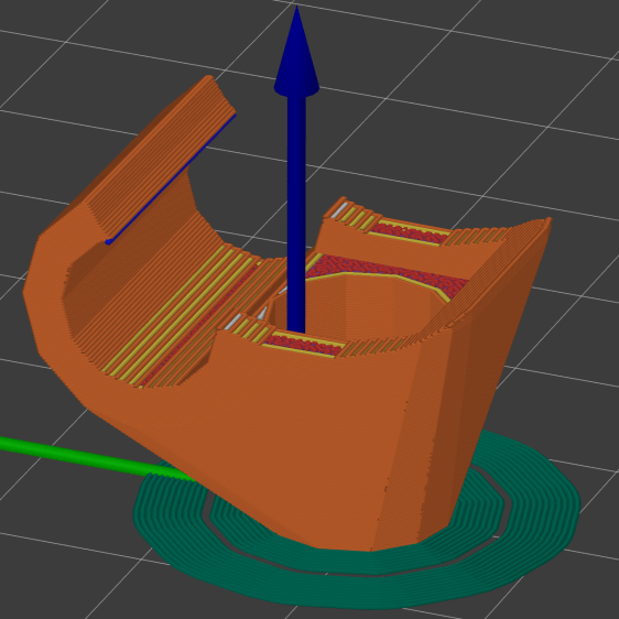
if (Layout == "BuildClip") |
|
rotate([-90,0,0]) |
|
HeadClip(); |
|
|
|
if (Layout == "BuildShiftCap") |
|
translate([0,0,CapBlock.z]) |
|
rotate([180,0,0]) |
|
ShiftCap(); |
|
|
|
if (Layout == "Case") |
|
ProgrammerCase(); |
|
|
|
if (Layout == "NutMold") |
|
NutMold(); |
|
|
|
if (Layout == "Upper" || Layout == "Lower") |
|
HalfClamp(Station,Layout); |
|
|
|
if (Layout == "Block") { |
|
ClampBlock(Station); |
|
if (false) |
|
color("Red", 0.3) |
|
Frame(); |
|
} |
|
|
|
if (Layout == "AllBlocks") { |
|
gap = 3*Block.x; |
|
for (i=[0:4]) |
|
translate([i*gap – 2*gap,0,0]) |
|
Clamp(i); |
|
if (true) |
|
color("Red", 0.3) |
|
Frame(); |
|
} |
|
if (Layout == "BuildBlock") { |
|
gap = 5.0; |
|
|
|
translate([gap,0,Block.x/2]) |
|
rotate([0,90,0]) |
|
HalfClamp(Station,"Upper"); |
|
translate([-gap – Block.z/2,0,Block.x/2]) |
|
rotate([0,90,0]) |
|
HalfClamp(Station,"Lower"); |
|
|
|
} |
|
|
|
|