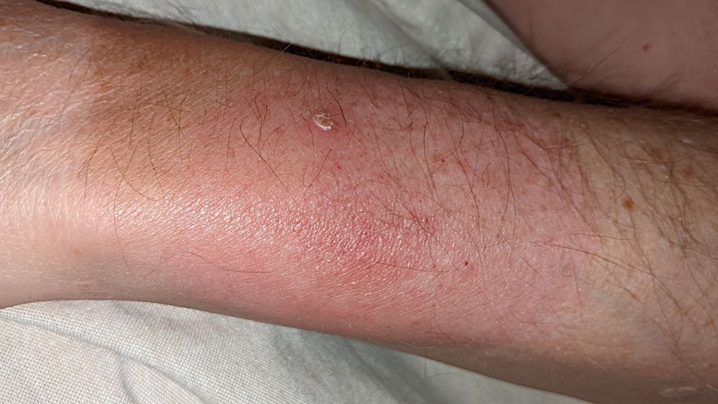
Two weeks of doxycycline should kill off all the Borrelia bacteria responsible for Lyme disease, but a blood test shows the antibodies:
Those antibodies will gradually disappear during the next few months and, unfortunately, a past Lyme infection does not prevent future infections.
The tick also injected Babesia parasites which do not respond to antibiotic treatment:

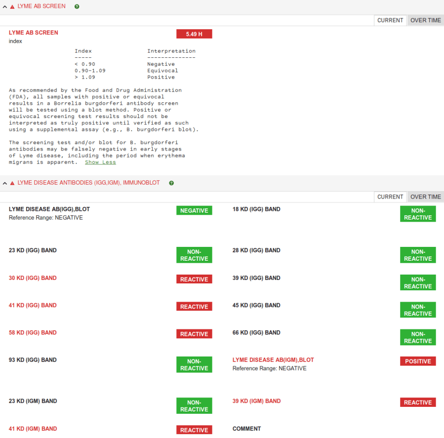
The “titer” refers to the dilution required to produce a negative test result, with the 1:64 reference titer representing six successive 50% dilutions. My blood required ten 50% dilutions to produce a negative result for the IgG antibodies and (presumably) six 50% dilutions from a 20% base for the IgM antibodies.
As I understand the situation, IgM antibodies appear promptly upon infection and IgG antibodies follow along later, so my reaction to the Babesia infestation was ramping up after two weeks.
In the Bad Old Days™, quinine was the go-to treatment for parasitic infections, but it has a host of horrific side effects at the dosage required for traction against actual diseases; tonic water ain’t gonna get you where you need to go.
The new hotness is atovaquone, arriving as 100 ml of a yellow liquid with the consistency of latex paint, (allegedly) the taste of “tutti fruitti“, and a price (modulo your drug plan) making inkjet printer ink look downright affordable. You might expect to get a 5 ml measuring spoon along the the bottle, but suffice it to say it’s an exceedingly good thing I’m well stocked for printer cartridge refilling.
All of the diseases and drugs list “fatigue” / “drowsiness” / “malaise” as symptoms / side effects and I’m here to tell you knocking off a couple of hours in the recliner during the day does nothing at all to disturb another nine hours in the sack overnight.
A few weeks of low productivity in the Basement Shop™ will definitely count as a successful outcome.
Protip: We need permethrin spray. Lots permethrin spray.