The Smell of Molten Projects in the Morning

Ed Nisley's Blog: Shop notes, electronics, firmware, machinery, 3D printing, laser cuttery, and curiosities. Contents: 100% human thinking, 0% AI slop.

Category: Machine Shop

Mechanical widgetry

  • Custom 45° Triangle Quilting Ruler

    Custom 45° Triangle Quilting Ruler

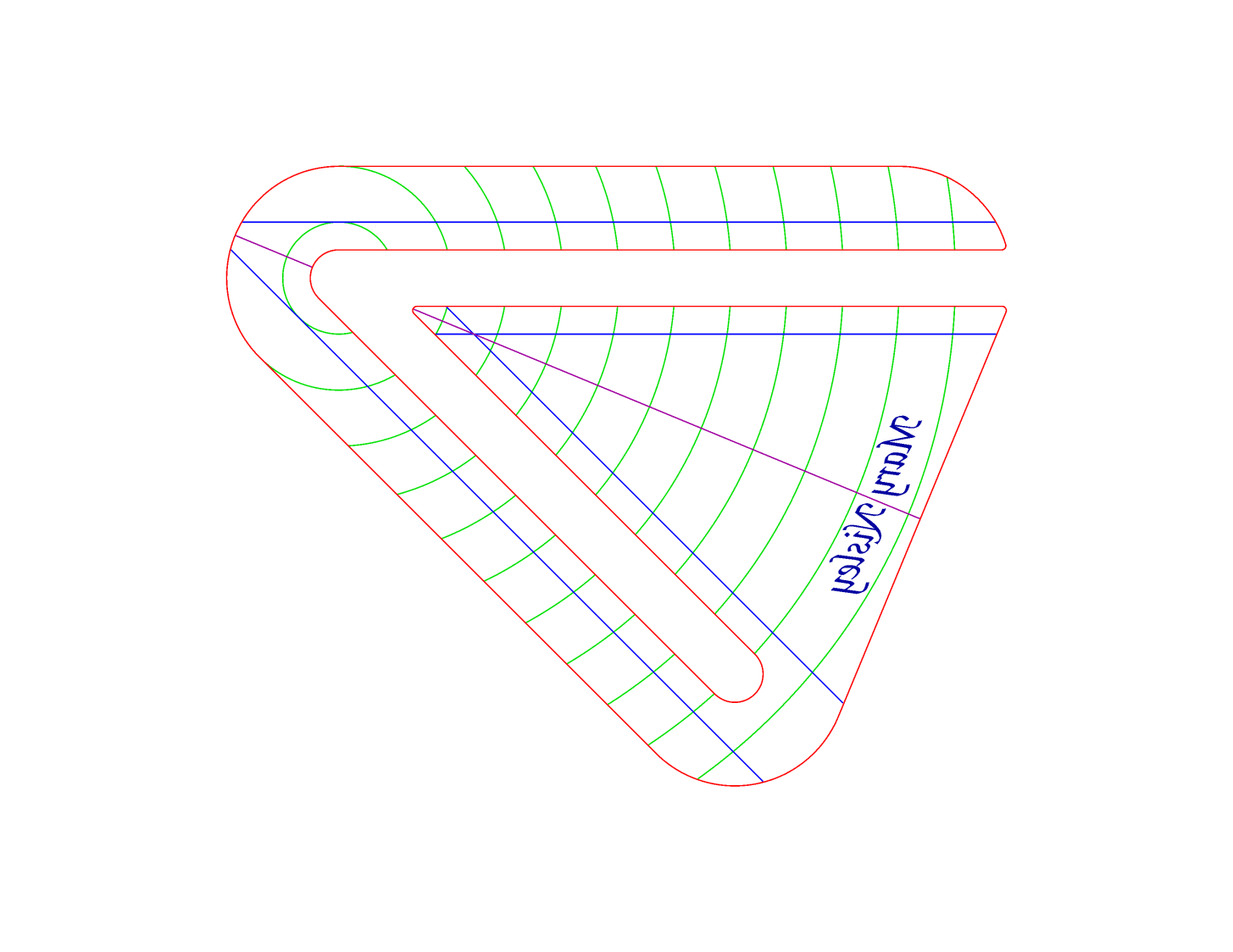
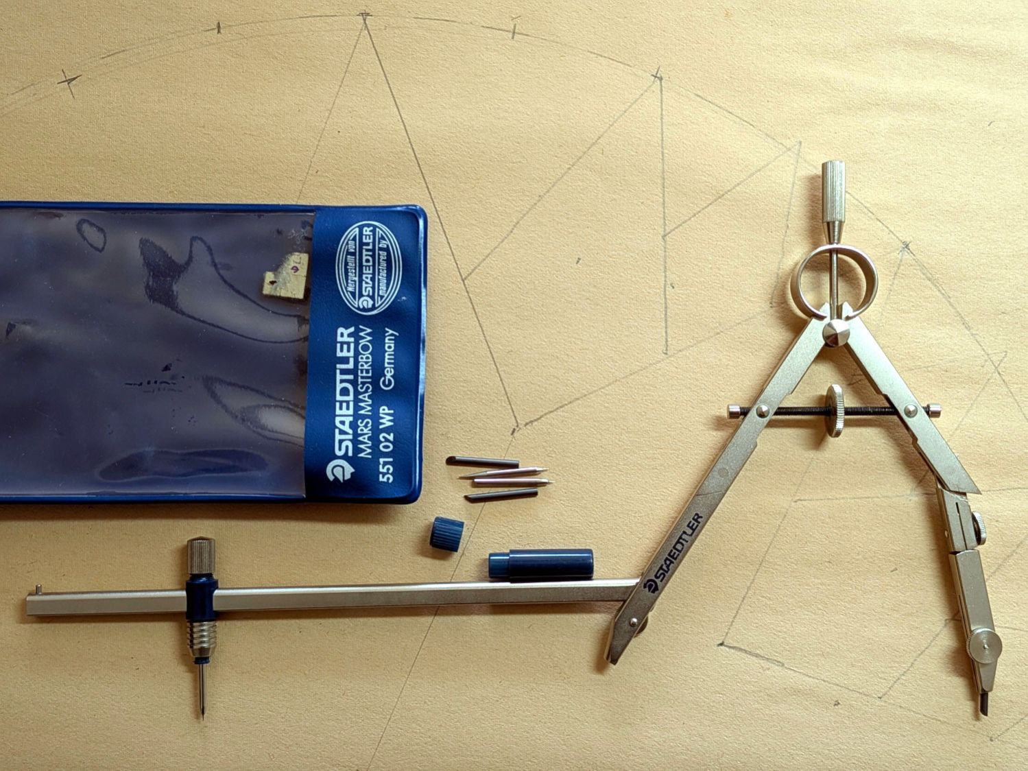
    Mary’s current quilt project has a corner design with an essentially infinite number of 45° triangles, which another custom ruler will simplify:

    45° Quilting Ruler - finished
    45° Quilting Ruler – finished

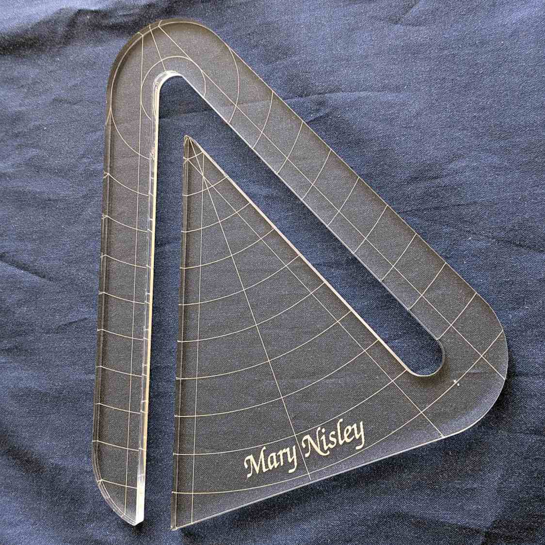
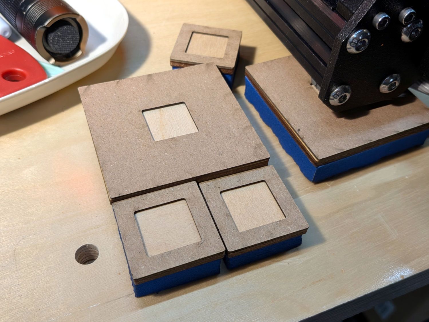
    That’s the end result of several iterations, proceeding from doodles to sketches to increasingly accurate laser-cut prototypes:

    45° Quilting Ruler - prototypes
    45° Quilting Ruler – prototypes

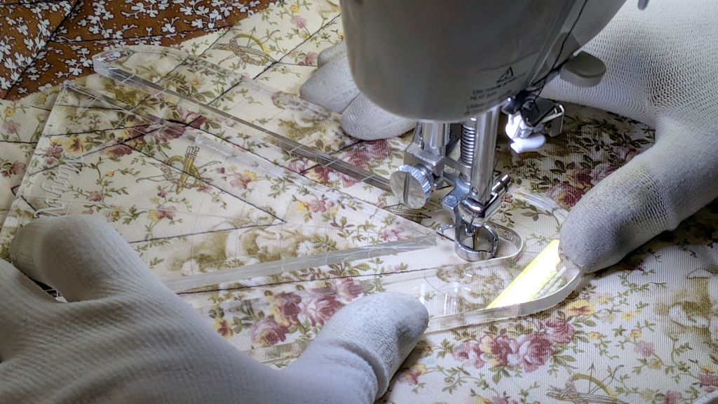
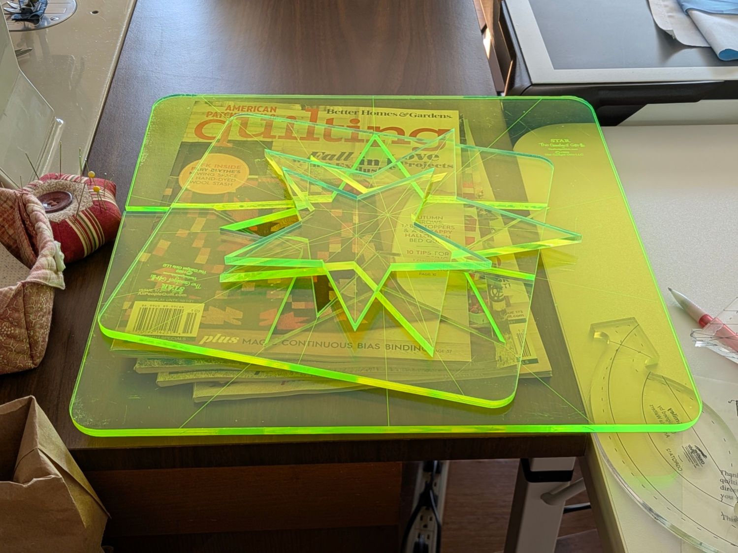
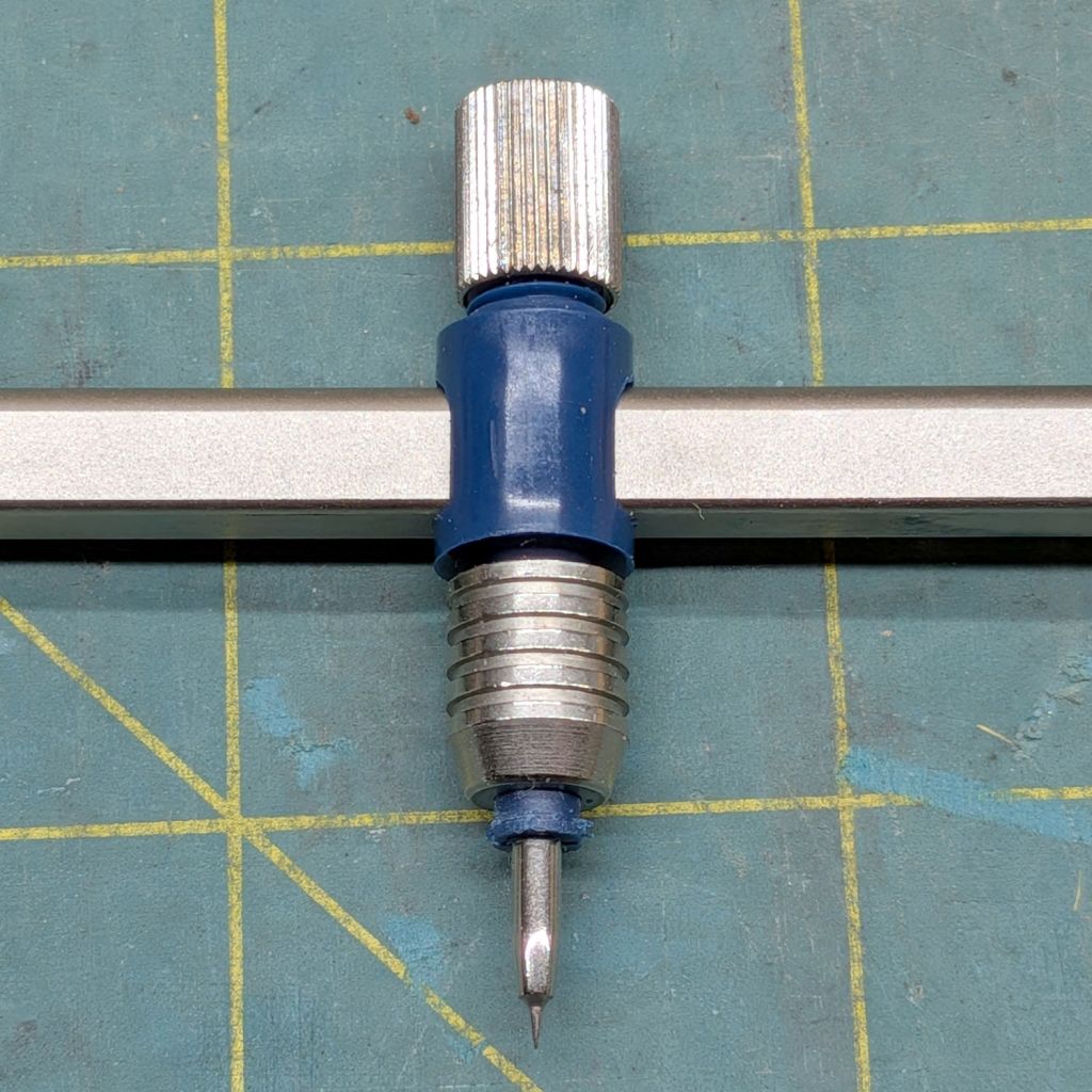
    A “ruler” in quilting parlance is a thing guiding the sewing machine’s “ruler foot” across the fabric (or, for sit-down machines, the fabric under the foot) in specific directions:

    45° Quilting Ruler - in use
    45° Quilting Ruler – in use

    That’s a practice quilt on scrap fabric: quilters need prototypes, too!

    The foot is 0.5 inch OD, within a reasonable tolerance, which accounts for the slot width in the ruler. It’s also intended to run against 1/4 inch thick rulers, which accounts for the thickness of that slab of acrylic.

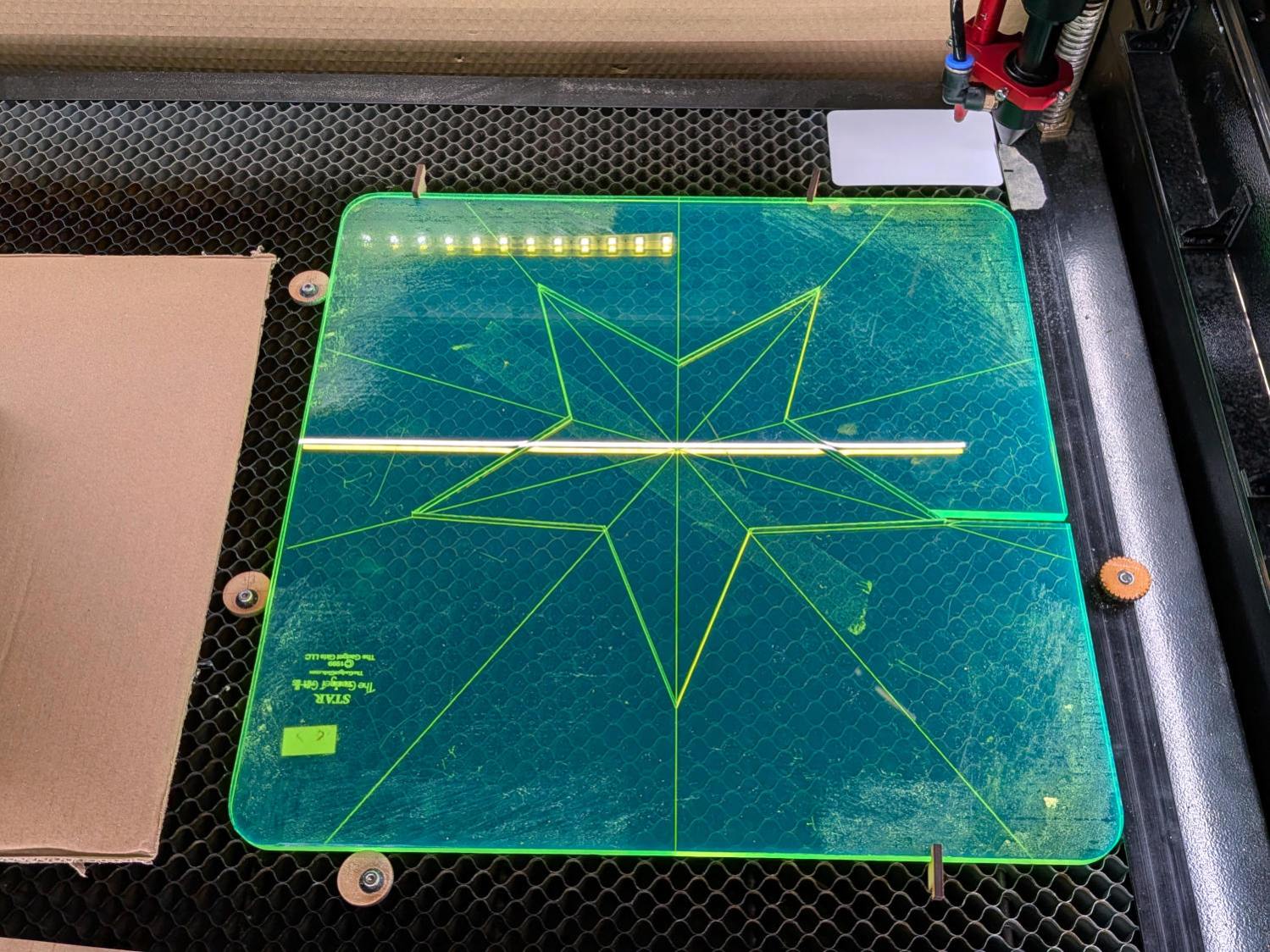
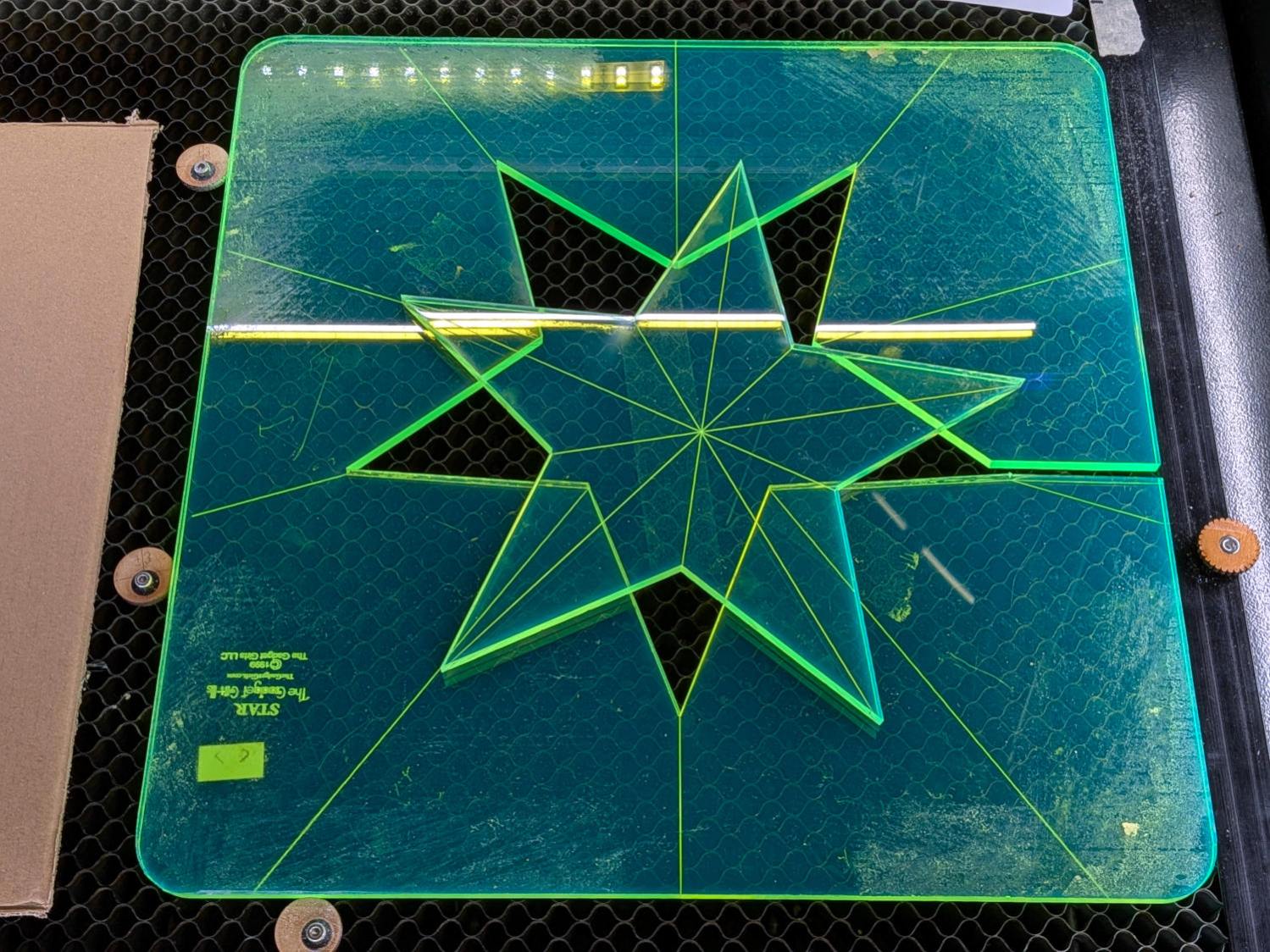
    The engraved lines & arcs are on the bottom of the ruler to eliminate parallax errors against the fabric, so the bottom is upward and the text is mirrored for the laser:

    45° Quilting Ruler - cutting
    45° Quilting Ruler – cutting

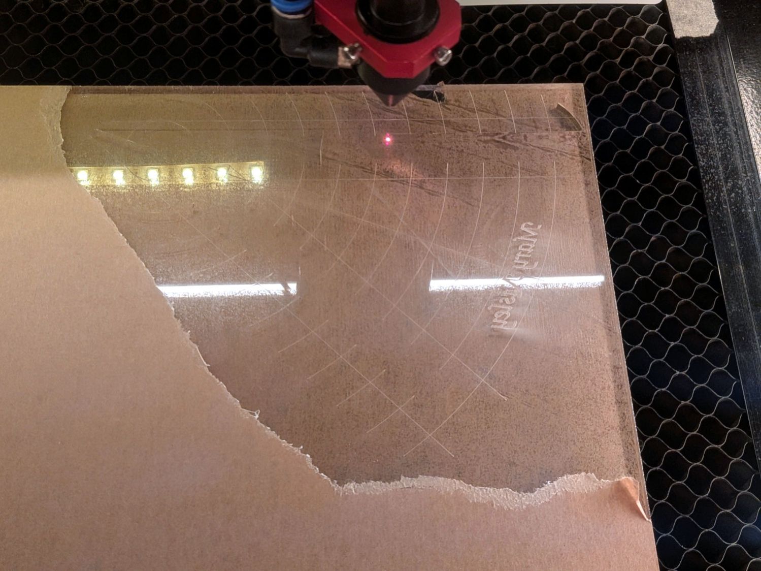
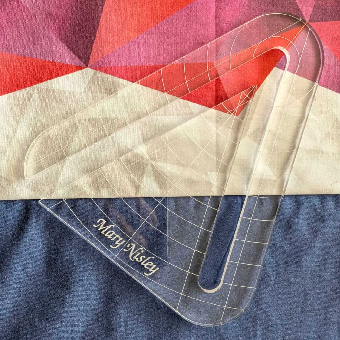
    Although fluorescent green acrylic may have higher visibility, clear seems adequate for the fabric in question:

    45° Quilting Ruler - colored fabric
    45° Quilting Ruler – colored fabric

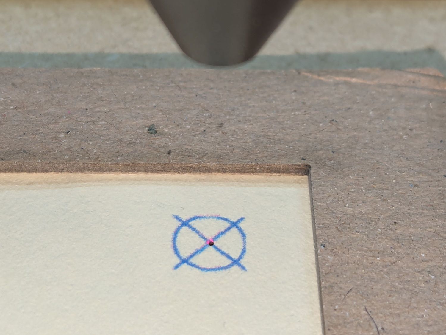
    I very carefully trimmed the arcs against the ruler outline using LightBurn’s Cut Shapes, which turned out to be a Bad Idea™, because the high-current pulse as the laser fires causes a visible puncture wound at the still-to-be-cut edge:

    45° Quilting Ruler - edge damage
    45° Quilting Ruler – edge damage

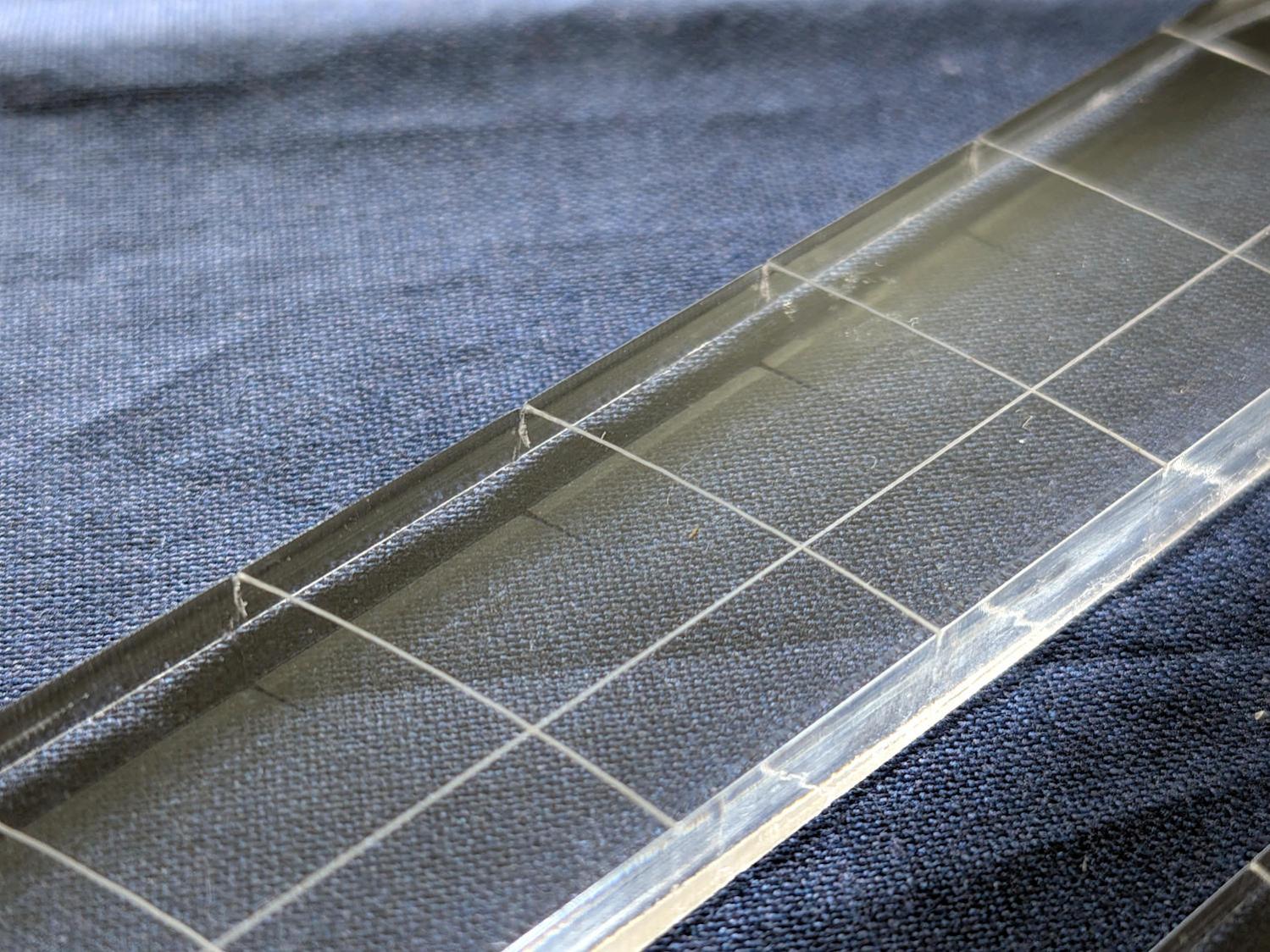
    Those are not straight lines and the plastic isn’t bent!
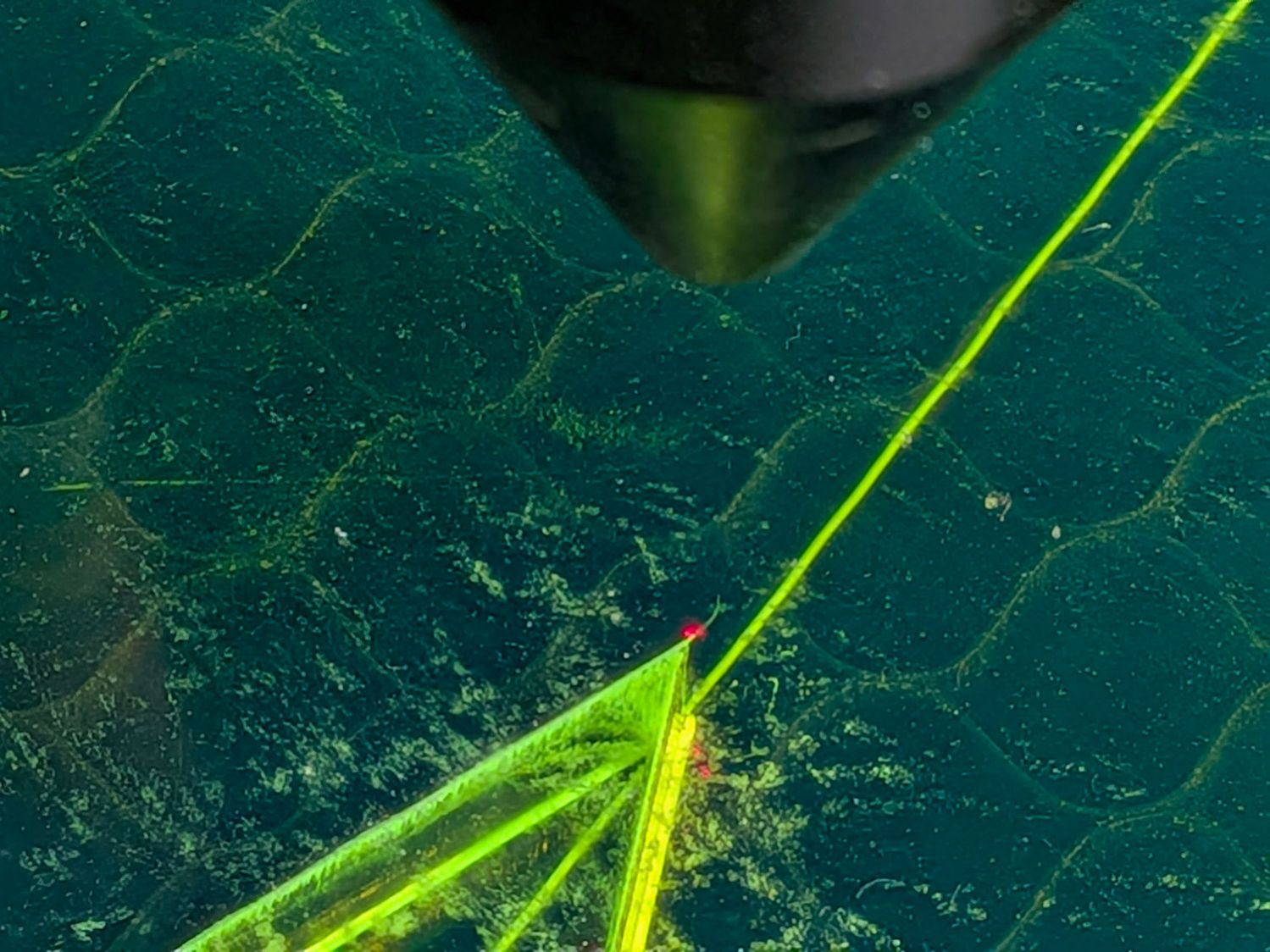
    A closer look:

    45° Quilting Ruler - edge damage - detail
    45° Quilting Ruler – edge damage – detail

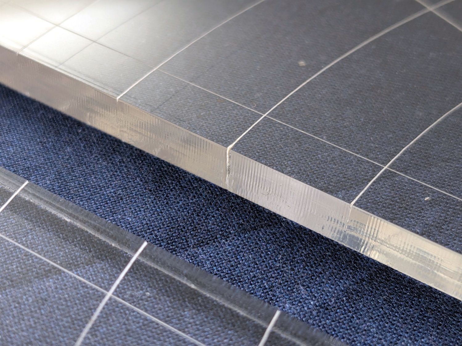
    The arcs without wounds started from their other end and stopped at the edge, which is perfectly fine.

    The wounds are unsightly, not structural, but the next time around I’ll extend the markings a millimeter beyond the edges into the scrap material.

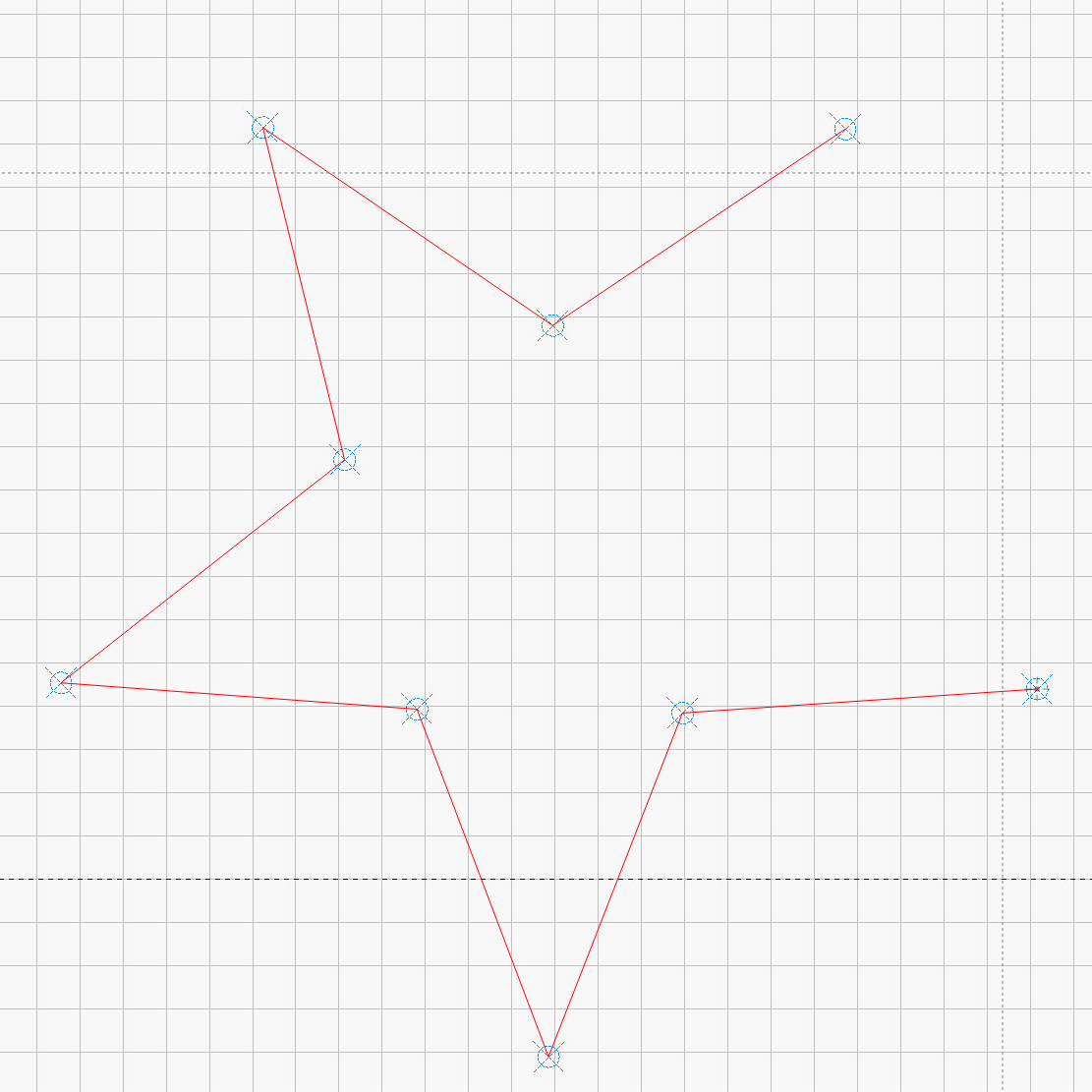
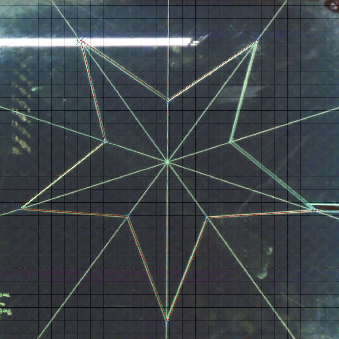
    The overall design looks busier than it is, because I put different features on different layers in case they needed different settings:

    45 Degree Quilting Ruler - LightBurn layout
    45 Degree Quilting Ruler – LightBurn layout

    The LightBurn SVG layout as a GitHub Gist:

    Loading
    Sorry, something went wrong. Reload?
    Sorry, we cannot display this file.
    Sorry, this file is invalid so it cannot be displayed.
  • Star Quilting Ruler Salvage: Laser Recutting

    Star Quilting Ruler Salvage: Laser Recutting

    Mary picked up a pair of Star quilting rulers from the Quilting Guild’s “exchange” table:

    Star quilting ruler - finished
    Star quilting ruler – finished

    They’re 1/4 inch laser-cut acrylic slabs dating back to the turn of the millennium, when laser cuttery wasn’t nearly as common as today. Apparently, the (now long gone) Gadget Girls had a problem with their laser: the larger star had eight of its ten lines not cut completely through the acrylic. The protective paper on the back had small perforations along a few of the lines, but nothing for most of them.

    Well, I can fix that.

    Lay the slab on the platform and lock it in place so it cannot move:

    Star quilting ruler - laser setup
    Star quilting ruler – laser setup

    That’s with the original bottom side facing upward, so the laser beam will hit the uncut part of the lines.

    Focus the laser atop some scrap 1/4 inch acrylic, then verify the red dot pointer is exactly concentric with the CO₂ beam by firing a test pulse, as in this punched card:

    Red dot vs printed target vs laser spot alignment
    Red dot vs printed target vs laser spot alignment

    Adjust as needed.

    Jog the laser to put the red dot pointer exactly at a star point:

    Star quilting ruler - laser point alignment
    Star quilting ruler – laser point alignment

    Hit Get Position in the Laser window so LightBurn knows where the laser head is located.

    I’ve added the targets I normally use for LightBurn’s Print and Cut alignment to its Art Library, so I dragged one to the workspace, then hit Move to Laser Position to snap the target directly onto that point of the star.

    Repeat for vertices along the star, then draw a multi-segment line = path between the target centers:

    Star Ruler Re-cutting - LightBurn layout
    Star Ruler Re-cutting – LightBurn layout

    That’s one continuous path from the upper right, counterclockwise around the star, ending in the center right. The missing pair of lines (and the vertex between them) were already cut, so I didn’t need to locate them.

    The camera view shows the alignment, although IMO the camera simply isn’t capable of such finicky alignment:

    Star Ruler Re-cutting - LightBurn layout overlay
    Star Ruler Re-cutting – LightBurn layout overlay

    As a confidence builder, I selected each target, moved the laser to that point, then fired a test pulse to verify the hole hit the vertex. In most cases, I couldn’t see the hole because it was within the original cut.

    My 60 W laser can’t cut through 1/4 inch = 6 mm acrylic in a single pass, so I use a 10 mm/s @ 60% pass to get most of the way through and a 20 mm/s @ 60% pass to complete the cut. That seemed excessive for a mostly cut path, but a single 20 mm/s @ 60% pass didn’t completely clear the uncut sections.

    So I used the normal two-pass cut and the star lifted right out:

    Star quilting ruler - victory
    Star quilting ruler – victory

    Happy dance!

    Although it is not obvious from the pictures, the star is not symmetric: it fits into the sheet in only one of its ten possible orientations. I will never know if that was a deliberate stylin’ decision or the result of hand layout before CAD spread throughout the land.

    I managed to locate the vertices so accurately that the repeated cuts left edges indistinguishable from the original cuts on the two free sides, which was a pleasant surprise.

    Mary promises to do something with those stars when she’s done with her current project(s). She may want the slab of acrylic around the large star trimmed into a smaller and more manageable decagon, in which case I will suddenly have a bounty of thick fluorescent green acrylic.

  • Staedtler Mars Masterbow 551 02 WP: Assembly & Tweakage

    Staedtler Mars Masterbow 551 02 WP: Assembly & Tweakage

    The corners of Mary’s current quilt project need a 16 inch diameter circle, but my Drawer o’ Drawing Tools that should hold the trammel (distinct from trommel) point & pencil for a steel rule came up empty. While the TEC drawing kit has an extension leg for its compass, IMO it’s entirely too flexy for general use.

    Further heap probes produced a Staedtler Mars Masterbow 551 02 WP compass with a robust extension leg:

    Staedtler Masterbow - 551 02 WP assembled
    Staedtler Masterbow – 551 02 WP assembled

    It was likely a surplus deal and, to the best of my knowledge, has never been used, so that picture documents how the extension leg fits into the compass. It arrived with the lead in that compass leg, causing some confusion.

    The key is to remove the point from that leg, insert the extension leg into the hole, then tighten the screw to clamp the leg in place:

    Staedtler Masterbow - leg socket
    Staedtler Masterbow – leg socket

    The collet holding the point was either manufactured incorrectly (which I find hard to believe, because Staedtler in a package embossed “Western Germany”) or suffered damage along the way, as the only point fitting into it stuck out much too far:

    Staedtler Masterbow - bow collet wrong point
    Staedtler Masterbow – bow collet wrong point

    The small container in the top picture held two spare leads and two other points:

    Staedtler Masterbow - point assortment
    Staedtler Masterbow – point assortment

    It turns out the blunt end of the bottom point should fit into the collet, but I had to ream the collet jaws with a (hand-turned in a pin vise) 2.1 mm drill to let that happen:

    Staedtler Masterbow - bow collet resized
    Staedtler Masterbow – bow collet resized

    Then everything lined up correctly and drawing could proceed, although the collet closer doesn’t (seem to) contribute anything to the proceedings.

    The thumbscrew adjustment on the compass makes it much more rigid, even with the extension leg sticking out there for an 8 inch span.

    I can (now) put the lead in the bow collet and the point in the compass, but IMO it’s easier to hold the compass while drawing around the circle. Your mileage, in the unlikely event you have one of these, may vary.

    They definitely don’t make them like that any more …

  • Prusa MK4 Foam Feet: Embiggened

    Prusa MK4 Foam Feet: Embiggened

    It turns out the Prusa MK4 weighs enough to squish my add-on foam feet to about half their original thickness:

    Prusa MK4 Foam Feet - embiggened
    Prusa MK4 Foam Feet – embiggened

    The two in the front are 30×30 mm and the shorter (more squished) foot was under the right rear of the MK4 where the power supply lives.

    The larger feet (one installed) are 60×60 mm and, with the same weight supported on four times the area, should squish much less.

    Stipulated: I can’t hear the difference either way.

    This project was precipitated by finding a large scrap of exercise mat foam in a place where it shouldn’t have been.

  • Magnetic Stirrer: Interior

    Magnetic Stirrer: Interior

    Of late, the magnetic stirrer mixing my morning cocoa occasionally doesn’t start spinning when I turn it on, which calls for some investigation.

    Removing the four obvious screws concealed under the rubber feet and prying off bottom cover reveals the trivial innards:

    Magnetic stirrer - interior
    Magnetic stirrer – interior

    The speed adjustment pot holds the little circuit board in place, with the green LED setting its jaunty angle.

    The motor spins a pair of neodymium magnets:

    Magnetic stirrer - magnet holder
    Magnetic stirrer – magnet holder

    I expected a gearbox instead of the direct drive setup.

    Perhaps those whirling neodymium magnets have been slowly demagnetizing the motor’s internal (alnico?) magnets.

    The motor brushes seem to be a pair of stiff wires, rather than carbon blocks, contacting the commutator, the wear from which may account for motor’s decreasing startup enthusiasm. Even though I didn’t expect a BLDC motor, this one may have been overly cheapnified.

    Perhaps kickstarting the motor with the steel fork I use to fish the stirrer magnet out of the mug will get the thing going.

  • Generator Cover Screw Knob

    Generator Cover Screw Knob

    The latches holding the side cover of the portable generator in place work well enough that I never tighten the cover screws, but sometimes one will vibrate itself into place and require less than one turn of a screwdriver to release. Given that I put a knob on the air filter screw, a pair of knobs on the side cover screws makes sense:

    Generator Cover Screw Knob - installed
    Generator Cover Screw Knob – installed

    Those are custom screws! The narrow neck keeps them captive in the cover, which is a Good Thing™.

    These knobs obviously descend from the air filter knob, with less knurling and a short shaft to clear the recess in the cover:

    Generator Cover Screw Knob - solid model
    Generator Cover Screw Knob – solid model

    Unlike the air filter knob, the double-sided tape gluing these to their screws isn’t continually compressed, so the knobs may eventually shake off. Should that happen, I’ll deploy epoxy.

    The OpenSCAD source code:

    // Generator cover screw knob
    // Ed Nisley - KE4ZNU
    // 2026-03-13
    
    include <BOSL2/std.scad>
    
    /* [Hidden] */
    
    // Screw head dome
    
    HeadHeight = 2.0;
    HeadOD = 10.8;
    
    DomeRadius = (HeadHeight^2 + (HeadOD^2)/4) / (2*HeadHeight);
    echo(DomeRadius=DomeRadius);
    
    KnobOD = 15.0;
    KnobLength = 10.0;
    
    ShaftOD = HeadOD;
    ShaftLength = 7.0;
    
    RimFudge = 0.3;   // ensures a printable edge
    
    // Build it
    
    difference() {
      cyl(h=KnobLength, r=KnobOD/2,anchor=BOTTOM,texture="trunc_pyramids",tex_size=[3.0,KnobLength/3]) position(TOP)
        cyl(ShaftLength,d=ShaftOD,anchor=BOTTOM);
      up(KnobLength + ShaftLength - HeadHeight + RimFudge)
        spheroid(r=DomeRadius,circum=true,style="icosa",anchor=BOTTOM);
    }
    
    
  • Wobbly Clothes Rack Repair

    Wobbly Clothes Rack Repair

    A clothes rack Mary intended use with some work-in-progress quilts seemed entirely too wobbly for the purpose, so I tried tightening its screws. This did not go well, as some of the threaded inserts sunk into the vertical bars spun freely and, with a bit of persuasion, pulled straight out of their sockets:

    Clothes rack screws - threaded insert penetrating oil
    Clothes rack screws – threaded insert penetrating oil

    The reddish fluid is Kroil penetrating oil I hoped would free the screws from the corrosion locking them into the inserts. After an overnight soak, they still required force majeure:

    Clothes rack screws - threaded insert in vise
    Clothes rack screws – threaded insert in vise

    The two inserts on the left came from the top of the rack and the other two from the bottom:

    Clothes rack screws - threaded insert corrosion
    Clothes rack screws – threaded insert corrosion

    Similar inserts have a hex drive recess and, because these are for 1/4-20 screws, I expected an inch size hex key. Nope, they want a hard metric 6 mm:

    Clothes rack screws - threaded insert reformed
    Clothes rack screws – threaded insert reformed

    I cleaned up the corroded inserts by the simple expedient of tapping them firmly onto the 6 mm wrench held in the vise:

    Clothes rack screws - threaded insert hex reforming
    Clothes rack screws – threaded insert hex reforming

    The crud around the bottom fell out of previous contestants during their reformation.

    I considered epoxying the inserts in place, but settled for tucking a thick paper shim into each hole:

    Clothes rack screws - threaded insert shim
    Clothes rack screws – threaded insert shim

    They’re entirely snug right now and, should they work loose, I’ll coat the hole with epoxy, roll up another shim, screw the insert in place, await curing, then declare victory and hope nobody must ever remove them.

    The 1/4-20 screws in the top member sit deep in recesses that surely had decorative wood plugs when the rack left the factory. Alas, they’re long gone, which may have let water / moisture corrode the screws + inserts . I’m not much good for “decorative” items, so this must suffice:

    Clothes Rack Screw Covers - solid model
    Clothes Rack Screw Covers – solid model

    A snippet of double-sided tape on one side of the hole keeps them in place:

    Clothes rack screws - cover installed
    Clothes rack screws – cover installed

    They look better in person …

    The trivial OpenSCAD source code:

    // Clothes rack screw cover
    // Ed Nisley - KE4ZNU
    // 2026-03-13
    
    include <BOSL2/std.scad>
    
    /* [Hidden] */
    
    NumSides = 4*3*3*4;
    $fn=NumSides;
    
    //----------
    // Build it
    //  … with magic numbers from the rack
    
    cyl(3.0,d=16.7,chamfer1=1.0,anchor=BOTTOM) position(TOP)
      cyl(6.0,d=12.9,chamfer2=1.0,anchor=BOTTOM);