Ed Nisley's Blog: Shop notes, electronics, firmware, machinery, 3D printing, laser cuttery, and curiosities. Contents: 100% human thinking, 0% AI slop.
The underside of a spinach leaf makes a fine place for a spider to guard her egg sac, right up until the leaf arrives on the kitchen cutting board just before breakfast:
Spider guarding egg sac
We deported her (and her incipient family) to the flower garden just outside, wished her well, and continued with breakfast.
We recently installed a Dripworks drip irrigation system for Mary’s garden and, of course, pre-assembled the emitter / dripline tubing, fittings, and supply / filter / plumbing for each of the beds in the Basement Shop. A few days after burying the main lines, plumbing the filter + pressure regulator, and plugging in half a dozen bed assemblies, Mary noticed some emitter tubes weren’t delivering any water and other beds seemed too dry.
N.B.: We bought everything directly from Dripworks. This is not counterfeit crap from a sketchy Amazon seller.
I cut the dripline just downstream of the Micro-Flowvalve on a completely dry bed, whereupon no water emerged. Cutting the supply tube just upstream of the valve produced a jet squirting halfway along the bed. I tried and failed to blow air through the valve: it was completely blocked despite being in the “open” position. I installed another valve and the emitter tube started working properly.
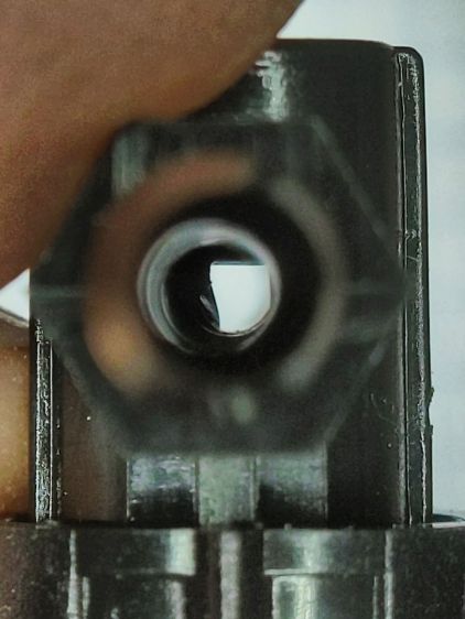
I sat down at the kitchen table with a bag of unused valves and peered through them (the pix are through the microscope):
Dripworks valve – mostly open lumen
That’s one of the better-looking valves, with only a little mold flash in the lumen.
Partially occluded lumens were more typical:
Dripworks valve – partially occluded lumen
Quite a few were almost completely obstructed:
Dripworks valve – mostly occluded lumen
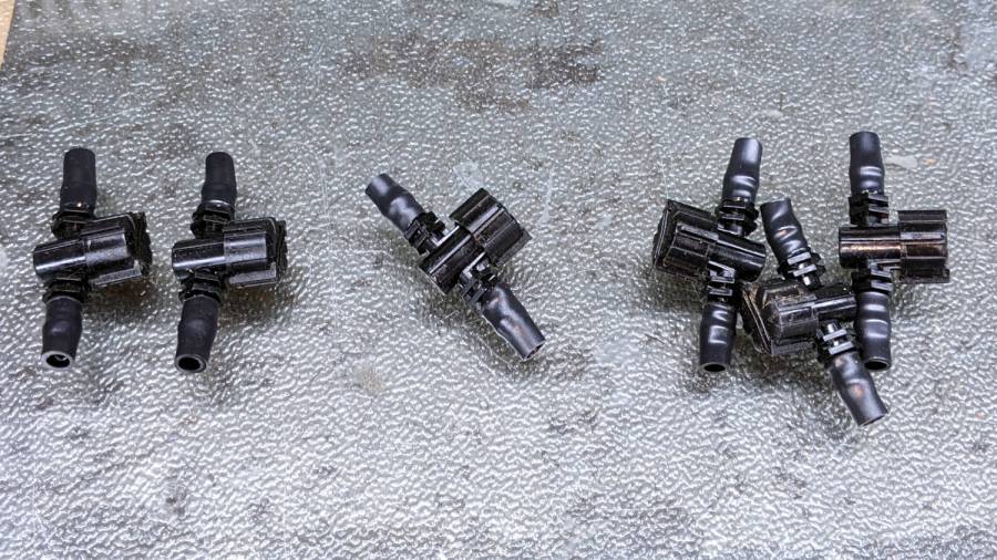
For lack of better instrumentation, I blew through the valves and sorted them by effort:
Dripworks valve – sorted by blockage
Two of the valves in the group on the left are completely blocked, with the others mostly blocked.
The middle group has enough mold flash to produce noticeable resistance to the air flow. I think water would have more trouble getting through, but the emitters would at least look like they’re delivering water.
The group on the right has mostly unblocked valves, with visible mold flash but little restriction.
I have no way to measure the actual water flow, so it’s entirely possible the QC spec allows considerable blockage while still delivering enough water to the emitters. More likely, the spec assumes a clear lumen and the mold flash is a total QC faceplant; it’s obviously not a controlled quantity.
Well, I can fix that:
Dripworks valve – drilling
That’s a 2.3 mm drill going straight through the valve body. I drilled the valves from both ends and blew out the swarf:
Dripworks valve – drill swarf
That produced twenty valves with clear lumens. Of course, the drill leaves a slightly rough interior surface, but it’s now much easier to blow air through them.
We hadn’t installed the driplines in two beds with three emitter tubes per bed. I cut out those six unused valves and sorted them by resistance:
Dripworks valve – six samples
Both of the valves on the left are blocked, the three on the right are mostly OK, and the one in the middle is partially blocked.
With two dozen repaired valves in hand, we returned to the garden, I cut 22 valves out of the installed driplines and replaced them under field conditions. Returning to the Basement Laboratory, I blew the water out (*), sorted them by resistance, and produced a similar distribution, albeit with no pictorial evidence. Although we have no immediate need for the used valves, they’re drilled out and ready for use.
In very round numbers, you should expect:
A third of Dripworks valves will pass (close to) the expected flow
A third will have a minor flow restriction
A quarter will have a severe flow restriction
One valve in ten will be completely blocked
Plan to drill out all the Micro-Flow valves before you assemble your driplines.
AFAICT, none of the other ¼ inch fittings we used have any interior flash, so it’s only a problem with the valves.
So these brief notes, compiled before I read the Okendo TOS, should serve the same purpose as an actual review, minus the nonsense of providing even more of my sensitive bits.
Bose discontinued their Hearphones last year. While I’m reasonably happy with how mine work, they seem to last about a year before something fails. Bose replaced the first unit after its covering delaminated, replaced the second unit when a wire failed in the left microphone, and the third unit is now approaching one year of steady use.
The Hearphone necklace curled around the IQbuds charging case:
Bose Hearphones – Nuheara IQbuds2 MAX
Comparing the IQBuds² MAX to the Bose Hearphones:
Heavier in the ears, but without the necklace
Poor battery runtime, both have non-replaceable batteries
Poor ear seal with silicone tips, OK with Nuheara’s foam tips
Immediate access to “World off” mode!
“World off” mode seems noisier, even with ANC on
Better dynamic noise control / filtering
The tradeoff for not having the Bose necklace is, of course, carrying a smaller battery in each ear. Everybody’s claimed run times are optimistic, but after a year the Hearphones still last the better part of a day, while new IQbuds generate range anxiety after a morning and must then spend a while recharging in their case.
The stock IQbud silicone tips exert entirely too much pressure on my ear canals. The foam tips produce a much better seal and were easier to wear for more than a few hours. The Bose “Stayhear” shaped silicone tips fit much better and suppress external sound just as well as the IQbud foam tips.
Replacing the stock IQbuds foam tips (described as “Comply memory foam”) with actual Comply memory foam tips directly from Comply was a definite step up that should not be necessary; they are similar, but visibly different. According to Comply’s online fit selector, you need their Isolation T-167 Sennheiser-specific tips, even though Nuheara hardware appears in Comply’s selector.
The IQbuds tap controls, except for the simplest single tap, barely work. I cannot perform a double-tap, because the bud registers the first tap as a single tap and either discards the second tap or registers it as another single tap. Long taps generally work, except when they don’t, having nothing to do with tap duration or force. Tech support tells me the buds use the audio signal to determine when a finger taps the bud, but AFAICT tap sensitivity is much too high and the discrimination entirely too unfussy.
Amusingly, nibbling dark chocolate can produce exactly the correct audio signal to trigger the “World off” tap in the right bud and, occasionally, the “Play / Pause” tap in the left bud. I rest my case.
For someone requiring far more audio gain than a typical hipster, firmly tapping an ear bud is an … uncomfortable … user interface.
Fortunately, a single correctly executed tap on the right bud mutes the microphones and turns on Active Noise Cancellation; the Hearphones bury that vital function on a tiny icon inside the Bose app, requiring many seconds to start and activate.
The IQbuds app (and, presumably, the bud firmware) does not allow assigning any tap function to any bud + tap pattern. For example, there’s no way to access both “change location” and “change focus” by tapping, because both those functions can be activated only by the right bud’s long tap: you may select one or the other. Weirdly, volume and media controls appear nearly everywhere and, if double taps worked, they’d be useful.
The Hearphones are much better at muting relatively quiet ambient sound, to the extent that I thought the IQbud “World off” function didn’t work. It does, even though it seems tuned to suppress much higher noise levels. Both do a surprisingly good job suppressing loud yard tools, perhaps due to my inability to hear frequencies over a few kHz.
The IQbud noise suppression exhibits horrible gain pumping in noisy environments and windy conditions. It rolls off the overall gain and filters the higher frequencies as the ambient noise increases, then restores them in a rush as the noise subsides: repeating the cycle as the noise level changes. This is very unpleasant and, AFAICT, there is no way to forcibly set a specific gain / bandwidth other than turning the suppression completely off, which misses the point.
Bottom line: I use the IQbuds and they definitely help my hearing, but I don’t particularly like them.
To be fair, I don’t like the Hearphones necklace very much, either, even though, overall, Bose did a better job with the actual earpieces.
The objective being to reduce the number of onion maggots in Mary’s Vassar Farm plot without chemical agents, I conjured sticky trap screen frames from the vasty digital deep:
Sticky Trap – first production run
Each one contains half a sheet of yellow sticky plastic, which is easy enough to cut before peeling off the protective covering sheets. The cage is half-inch galvanized hardware cloth snipped with hardened diagonal cutters. A bead of acrylic adhesive around the base holds the cage in place
Although you can deploy sticky sheets without cages, they tend to attract and affix beneficial critters: butterflies, small birds, furry critters, toads, gardeners, and the like. We don’t know how effective the cages will be, but they seemed better than nothing.
They mount on ski poles cut in half:
Sticky Trap – ski pole installed
And on fence posts around the perimeter:
Sticky Trap – angle bracket installed
To my untrained eye, some of those doomed critters are, indeed, onion maggot flies. The rest seem to be gnats and other nuisances, so IMO we’re applying population pressure in the right direction.
Each base-and-cap frame takes about three hours to print, so I did them one at a time over the course of a few days while applying continuous product improvement.
The sheets rest on small V blocks intended to keep them centered within the cage:
Sticky Sheet Cage – angle bracket – solid model
The ski pole attachment must build with the cap on top, but it bridges well enough for the purpose:
Sticky Sheet Cage – ski pole – solid model
The overhanging hooks on the blocks (just barely) engage the grid to keep the lid in place, while remaining short enough to not droop too badly. You could probably delete the hooks from the bottom plate, but they align the cage while the adhesive cures.
The sheets tend to bend in the middle, so I’ll stick a thin slat or two vertically to keep them straight.
This file contains hidden or bidirectional Unicode text that may be interpreted or compiled differently than what appears below. To review, open the file in an editor that reveals hidden Unicode characters.
Learn more about bidirectional Unicode characters
For what should be obvious reasons, we armored Mary’s “kitchen garden” with buried concrete blocks and deer fence. I secured the fence to 7 foot plastic-coated steel-core posts strapped to shorter stakes supporting the lower wire fence, using cable ties we both knew wouldn’t survive exposure to the sun.
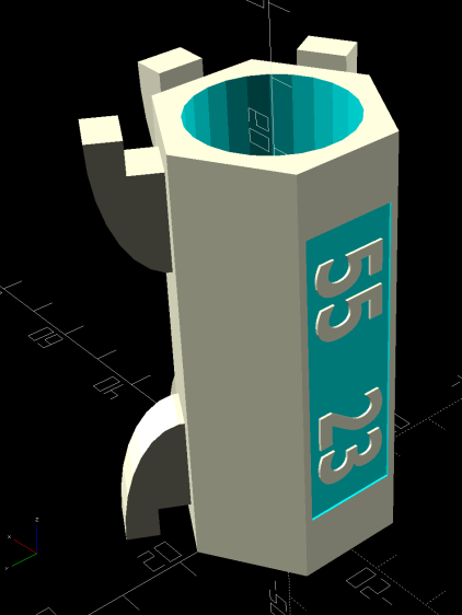
As part of the spring garden prep, I summoned proper supports from the vasty digital deep:
Deer Fence Hanger – Build view
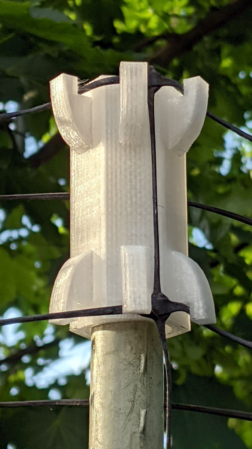
The general idea is to plunk one atop each post and tangle wrap the netting through the hooks, thusly:
Deer Fence Hanger – installed
The garden looks like we killed an entire chess set and impaled their carcasses as a warning to others of their kind, but the fence now hangs neatly from the top of the posts rather than drooping sadly.
Each one of those things takes nigh onto two hours to emerge from the M2, so I printed them one by one over the course of a few days while making continuous product improvements.
The “natural” PETG isn’t UV stabilized, either, but it ought to last longer than those little bitty nylon cable ties. We shall see.
This file contains hidden or bidirectional Unicode text that may be interpreted or compiled differently than what appears below. To review, open the file in an editor that reveals hidden Unicode characters.
Learn more about bidirectional Unicode characters
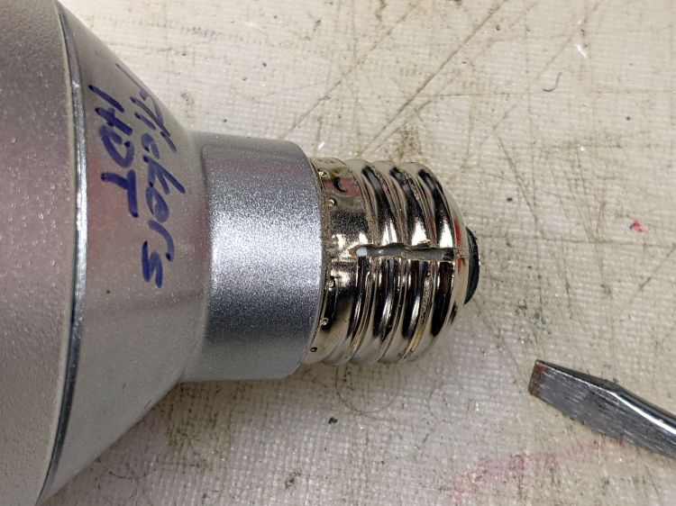
One of those LED spotlights may have barely outlasted its worthless warranty, but not by much, and has been languishing on the back of the bench with “Flickers hot” scrawled on its side.
The metal base didn’t respond to twisting, so I slit the threads with a cutoff wheel:
Satco PAR30 – thread slit
Applying the screwdriver removed the base to reveal a silicone rubber casting:
Satco PAR30 – thread silicone
The small wire emerging near the edge of the plastic case seems to be the neutral contact to the shell, with a poor enough joint to suggest it might have been why the lamp flickered when it got hot.
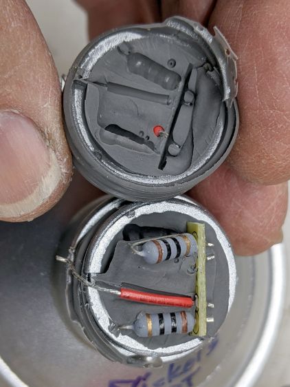
Some brute force snapped the silicone off at the bottom of the plastic case and broke the two wires bringing AC to the PCB:
Satco PAR30 – thread silicone base
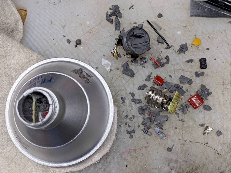
Digging around inside produced a debris field of silicone crumbs, broken resistors, torn caps, and various other components, with zero progress toward removing the shell:
Satco PAR30 – silicone extraction
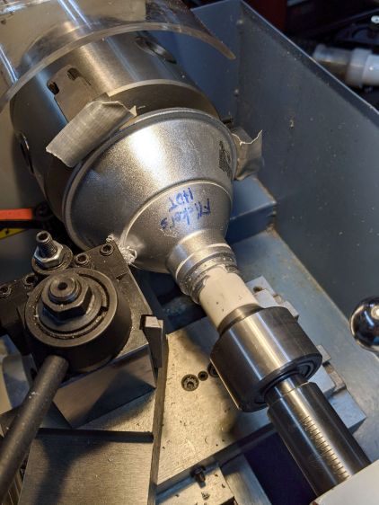
A little lathe work converted a chunk of PVC pipe into a crude mandrel supporting the mangled case:
Satco PAR30 – base cutting setup
A few millimeters of sissy cuts released a silicone O-ring sealing the shell against the reflector:
Satco PAR30 – O-ring seal
Continuing the cuts eventually revealed the three screws holding the shell to the reflector and the two wires powering the LED:
Satco PAR30 – reflector separated
Chopping off the screws with a diagonal cutter freed the shell and revealed the top of the PCB:
Satco PAR30 – electronics top
It really does have a surprising number of components!
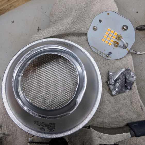
Those three screws connected the LED panel / heatsink to the shell through the back of the double-walled reflector. More brute force peeled the outer shell away and released the panel:
Satco PAR30 – lens assembly
Each of the 5050 packages contains a pair of white LEDs with 5.2 V forward drop for the pair, at the very low test current. They’re all in series, so you’re looking at well over 60 V total forward drop:
Satco PAR30 – LED panel detail
Note that the wiring, which nobody will ever see, follows the electrical color code of white = common and gray = hot.