Ed Nisley's Blog: Shop notes, electronics, firmware, machinery, 3D printing, laser cuttery, and curiosities. Contents: 100% human thinking, 0% AI slop.
Our daughter snagged some tchotchkes from a high-school career fair, including one that she instantly recognized as a flamethrower: Antibacterial Hand Sanitizer Spray, 62% Ethyl Alcohol plus some other junk, in a handy pump-spray container. Heck, it even says
Warnings Flammable. Keep away from open flame. Keep out of reach of children.
I was so proud of her…
Flare3.gif
After homework, she stuck a candle atop the garbage can by the garage and fired off a few shots while I ran the camera. Here’s the best one, converted to a low-speed animated GIF.
We’re pretty sure that’s Sweet Babby Jeebus™ in the next-to-last frame of the flare. Maybe Madonna. Could go either way.
Much as with the “movies” I made for trebuchets and tree frogs, I used ffmpeg to shred the camera’s mpg movie into separate jpg images, some bash to select the frames, then convert to stitch them back together into a gif.
The general outline:
mkdir Frames
ffmpeg -i mov04990.mpg -f image2 Frames/frame-%03d.jpg
cd Frames
mkdir flare3
for f in `seq 760 780` ; do cp frame-${f}.jpg flare3 ; done
cd flare3
convert -delay 50 frame-* Flare3.gif
If my bash-fu was stronger, I could feed the proper file names directly into convert without the copy step.
Now, kids, don’t try this at home. At least not without responsible adult supervision…
Just chopped up a 5-lb lump of Provolone into 2-oz chunks for pizza, which brings this simple shop project to mind: a cheese garrotte.
It’s about a foot of 0.011-inch (call it 0.25 mm) stainless steel wire with the ends wrapped around some aluminum rod, neatly tied off with heatshrink tubing.
Usage is about what you’d expect: it cuts cheese like nothing else on earth. The only trick is maintaining a straight line, which is easier (for me, at least) when I cut vertically downward.
It’s difficult to cut all the way to the bottom and that wire is rough on the fingertips, so I tend to flip the cheese over and pull sideways for the last inch or two. Maybe not a perfect cut, but good enough.
Cheese Garrotte Handle Detail
Construction nuance: loop the wire around the handle once or twice, pass it through the hole, then do another loop before twisting the end. If you run the wire directly through the hole, it’ll break on the far-side sharp edge after a while, even when you countersink the hole.
I put a shallow groove around the handle, but that’s likely not needed. You can certainly get fancier with the handles if you like. This one is dishwasher safe, which makes up for a lot.
You really, really need heatshrink tubing over the bare wire ends, as the tip of a 11-mil stainless wire is indistinguishable from a needle.
For about the last week I’ve noticed a soft clicking-buzzing sound somewhere near the dashboard / center console of our 2000 Toyota Sienna. I tried some on-the-fly isolation, but it wasn’t related to motion, engine on/off, CD or tape player, fan, or anything else. Finally Mary noticed it, too, and we spent half an hour in the garage yanking fuses and wiggling things until we tracked it down to below the passenger seat.
Now, in the good old days, that was empty space, but in the Sienna it’s where the rear-area heater lives. Shoving the seat forward to the stop exposed the heater and, sure enough, it’s buzzing and clicking. Intermittently, somewhat randomly, but very steadily.
Rear Temperature Control
With that as a hint, I twisted the rear-area temperature control (on the headliner behind the driver seat) and shazam the noise stopped. The control has detents and when moving the control to each detent the heater makes a faint buzzing. I suspect the control adjusts a valve that regulates engine coolant flow inside the heater.
It’s not obvious whether the control is a pure-digital rotary encoder or a potentiometer, so I decided to investigate: it’s already sorta busted, what’s to lose? The bezel comes off by prying its door-side edge outward. The white plastic frame has two screws into the metal structure under the roof. The two electrical connectors are, of course, the positive-latching kind that you pull the little tab until you break your fingernail and then realize that you should push it instead.
Temperature Control – Interior View
Taking the control apart reveals that it’s a potentiometer with some switching contacts. The two bifurcated spring-finger contacts on the black plastic disk short the resistive element to the inner metallic track.
Resistive Element
The metal contacts appeared slightly grody, but with no major corrosion. The resistive track looked just fine.
The offending control position would be to the left side of the element as shown in the pictures here: there’s nothing obviously wrong at that spot. I think the maximum-heat position is off the resistive element entirely, resting on the far left end of the metal traces, but the control wasn’t quite set to that spot. Perhaps the problem was that the contacts became intermittent at the exact edge of the element.
I smoothed the collection of anti-oxidation grease over the tracks, covered the contacts with their own blobs, put everything back together, and it works fine.
We tend to put the control at A/C during the summer and at maximum heat during the winter. I suppose the poor thing got frustrated after we moved it a month or so ago…
The money saved with this repair might just pay to have the Toyota dealer replace the spark plugs. The shop manual says that task starts by removing the windshield bezel and all the stuff above the engine intake manifold; the job costs upwards of 300 bucks. I can barely see the rear plugs with a looong inspection mirror angled just so while lying on the floor under the van, so it’s truly a nontrivial operation.
Several decades ago I got my esteemed wife a ten-pound Hershey bar for Christmas. She said that was a thoughtful gift, exactly what she wanted, and if I ever did that again, she would kill me.
Turns out that I’d gotten such a bar myself, many many years ago…
These days, of course, the biggest Hershey’s Chocolate bar you can get is a measly five pounds.
I’m sure they have more different versions of these things than anyone can count, but when I unscrewed the kitchen sink aerator, this is what I found inside.
The yellow plastic filter actually has two parts, held together by a minuscule clickstop on the central post. You can pry the whole thing off the main body with your thumbnail or, as in the photo, just pop the top screen off.
Rinse the grit off the screen, snap it back together, screw everything back onto the spout. Done!
It’s amazing how much grit accumulates downstream of the whole-house water filter. On the other paw, having just replaced the water heater, I’m not that amazed.
Once again, the faucet O-ring seals are leaking. This happens about every two years, perhaps due to mineral buildup in the spout body despite the water softener. Fortunately, it’s a dribble rather than a spurt, so it’s not an emergency.
This is a Home Depot (or was it Lowe’s?) faucet, but they do not stock repair parts. Go to FaucetDirect.com, order these parts:
060366-0070A SPOUT SEAL KIT (on the main column)
060343-0070A SPACER WITH O-RINGS (below the valve cartridge)
030126-0070A BUTTON AND SCREW KIT (if you booger the button)
Popping off the button
Of course, order two or three of each, because FD has punitive shipping rates. Ten bucks for a few envelopes of O-rings? Sheesh… but the last time I tried to get ’em locally, they were No Stock. If I’ve got to wait around, I’ll have ’em delivered to my door.
[Update: that comment suggests you can now get ’em from Amazon.com]
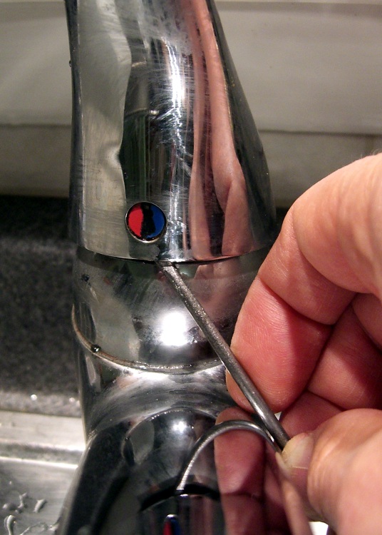
The first puzzle is how to get the faucet apart. After making a mess of it the first time, it turns out you poke a small flat screwdriver inside the handle and pop the red-blue button out. It’s held on by two small tabs, one on each side, and if you can just push one then it’ll ease right out. It is not a screw head, despite the recessed slot down the middle.
Poke a 3/32″ hex key in the hole, back out the setscrew a few more turns than you think it takes, pull the handle off.
The plastic cap retainer has two arms holding the escutcheon ring in place. Push inward, remove the escutcheon. The retainer is probably hopelessly jammed into the top of the faucet spout, so if it doesn’t come out, that’s OK.
Loosen the three screws holding down the valve cartridge, pull it straight up and out. You did turn the water off first, right? Remove the plastic spacer plate and three O-rings below it if you can; the plate may not fit through the retainer.
Faucet column
Now, get comfortable on the sink. Pull-and-twist the spout straight up with far more force than you think necessary. It will suddenly fly off and bloosh the water that’s been standing in the faucet column all over the place.
You’re left with a rather grody column and the two offending O-rings. Note the orientation of the silver flange ring at the bottom and the lower white plastic bearing ring. There may be three O-rings stuck to the top surface; they belong inside the spacer plate.
Remove all that hardware and scrub the grodosity off the column.
Hint: if you’re weak of stomach, never look inside your drinking water fixtures, because you’ll never drink tap water again.
I generally soak the spout in vinegar for a bit, scrub it out with a toothbrush, ease the remaining deposits off with a small screwdriver, then scrub the whole thing down with a ScotchBrite pad.
I apply a very very very thin layer of silicone lubricant to the bearing surfaces inside the column, which makes the next step possible.
Put the flange ring, the new O-rings, and plastic bearing rings in place, then slide the spout assembly straight down over the column until it bottoms out with a thump.
Install the new spacer plate & its O-rings, then reassemble all the other doodads in reverse order, turn on the water, and you’re done.
Then forget all the crud you saw in there that you couldn’t clean out.
Surprisingly, the flashlight holding these cells wasn’t damaged.
Judging from the position of the switch, my mother tried to turn the thing on, it didn’t light up, and she just dumped it back in the drawer. Time passed, corrosion never sleeps, and the weak link (fortunately, between the two cells) let the alkaline nastiness out.