Ed Nisley's Blog: Shop notes, electronics, firmware, machinery, 3D printing, laser cuttery, and curiosities. Contents: 100% human thinking, 0% AI slop.
Got a package from halfway around the world that, I thought, corresponded to a recent eBay order. Opened the envelope and pulled out a box containing … a Digital Media Player?
That’s odd. I don’t recall ordering one of those.
At this point, anybody who’s read Frank Herbert’s The White Plague should get the chills. Do you or don’t you open a mysterious package from far away that seems to offer something interesting?
Well, open it I did, and found exactly what I’d ordered: a stash of female headers pins. Of course, one can’t tell what else might have come in the package, but so it goes.
Now I can hand Eks half a lifetime supply of the strips to replace the ones I mooched.
One other mildly surprising part of the package: it seems we’ve gotten to the point where magnetic closures are cheap enough to replace everything else, including intricate origami tucks. There’s a small steel plate pasted under the flap. Who knew?
‘Twas the night before September, when outside the house
Many creatures were stirring, not just a mouse;
The garden was fenced all ‘round with care,
In hopes that deer would never come there;
My daughter was nestled all snug in her bed,
While replays of band practice ran through her head;
My husband was sleeping, and hoped for much more,
As I settled down for a short summer snore.
When out in the yard there arose such a clatter,
I sprang from the bed to see what was the matter.
Away to the window I flew like a flash,
But saw nothing on the deck; what was that crash?
Then off to the kitchen to flip on the lights,
To better reveal the outermost sights.
When, what to my wondering eyes should appear,
But an eight pointed buck: a powerful male deer!
His head, it was lowered; his mouth, it was red,
He looked mean and angry, a monster to dread.
When he moved I saw a most terrible sight,
His antler was tangled in the fence very tight.
I ran for my husband, to wake him from sleep,
He groggily blinked, then from the bed he did leap.
We dashed to the doorway, but the buck, he was gone,
One glimpse of my motion made him quite strong.
We surveyed the garden with the help of a light,
What destruction was done before the buck’s flight?
Alas! My poor garden, damage lay all around,
Two heavy steel fence posts he’d bent to the ground.
The ruin was total in two veggie beds:
Stalks twisted and broken, big leaves lay in shreds.
We pushed the posts upright, unsnarled all the net,
As we patched the fence up, we felt it was wet.
Shining flashlight on hands revealed blood on our fingers,
But it was not ours: could deer blood still linger?
Sunshine the next morning revealed all of the damage,
Plus an antler tip broken in the buck’s desperate rampage.
The rabbits and woodchuck say “Thanks Mr. Buck!
You’ve opened the garden, it’s our great luck!
We’re feasting on beet greens, parsley and chard,
To fatten for winter is no longer hard.”
We wish you happy holidays, filled with warmth and good cheer,
And may your next growing season have gardens without deer.
Folks: I couldn’t make this one up; that is exactly what happened. I believe the buck was grazing on fallen apples from my neighbor’s tree when, in the dark, his antlers tangled in my fence netting. They were velvety, still soft and growing, so when he broke a tip trying to escape, there was blood all over. At 2:00AM I was outside, stringing up twine and drenching it with deer repellent, hoping to keep the rest of his herd from testing my jury-rigged fence.
Acknowledgments: Thanks to Clement Clarke Moore and his “The Night Before Christmas” for the shape of this poem and for my lines 9-11. His words fit the situation so well that I couldn’t resist using them.
Ed says: It’s Christmas: we can take the day off from tech, right?
The bottom glass shelf in our Whirlpool refrigerator (the “Crisper Cover”) rests on an elaborate plastic structure that includes slides for the two Crisper drawers. Perhaps we store far more veggies than they anticipated, we’re rough on our toys, or the drawer slides came out a whole lot weaker than the designers expected. I’m betting on the latter, but whatever the cause, the two outside slides broke some years ago.
I don’t know what function the rectangular hole above the flattened part of the slide might serve, but it acted as a stress raiser that fractured the column toward the front. With that end broken loose, another crack propagated toward the rear, so the entire front end of the slide drooped when the drawer slid forward.
The minimum FRU (Field Replacement Unit) is the entire plastic shelf assembly, a giant plastic thing that fills the entire bottom of the refrigerator. You could, of course, buy a whole new shelf assembly, perhaps from www.appliancepartspros.com, but it’s no longer available. Back when it was, I recall it being something on the far side of $100, which made what you see here look downright attractive.
My first attempt at a repair was an aluminum bracket epoxied to the outside of the slide, filling the rectangular opening with JB Industro-Weld epoxy to encourage things to stay put. The plastic cannot be solvent-bonded with anything in my armory, so I depended on epoxy’s griptivity to lock the aluminum into the shelf. That worked for maybe five years for the right side (shown above) and is still working fine on the left side.
Refrigerator shelf bracket – bottom
The right-side bracket eventually broke loose, so I did what I should have done in the first place: screw the bracket to the shelf. Alas, my original bracket remained firmly bonded to the bottom part of the shelf and secured to the block of epoxy in the rectangular hole. Remember, the broken piece didn’t completely separate from the shelf.
So I cut another angle bracket to fit around the first, drilled holes in the shelf, transfer-punched the bracket, and match-drilled the holes. Some short(ened) stainless-steel screws and nuts held the new bracket in place and a few dabs of epoxy putty filled the gaps to make everything rigid.
That’s been working for the last few years. The refrigerator is going on 16 years with only one major repair (a jammed-open defrost switch), so I’ll call it good enough.
MTD used the same design for the gasoline tank caps on our leaf shredder and snow thrower: an aluminum cone (which evidently serves to keep splashes away from the tank vent) mounted on a heat-staked plastic rod molded into the cap. It’s straightforward, but a bit suboptimal for high-vibration yard gadgets.
The aluminum cone eventually worries its way through the plastic post and falls into the tank, taking the heat-formed button from the post along with it. Trust me on this, fishing those things out of the tank is an exquisite little inconvenience.
4-40 screw post – inside4-40 screw post – exterior
The fix is straightforward.
Chop off the remains of the post, drill a snug 4-40 tapping hole straight through the cap, and tap it accordingly. Secure the cone to the screw with a nut tightened against the head, run the screw through the cap, run a pair of nuts onto it, trim to length, then jam the nuts together so the cone is about where it started out. Loctite on the nuts is a Good Thing, but I don’t know how it feels about gasoline immersion.
The snowblower cone is getting wobbly; I must make a preemptive strike on it to avoid fishing the debris out of the tank.
We took down the deer netting around the garden yesterday, which involves pulling a zillion staples out of the wood posts. I put some salvaged hard-drive head motor magnets to good use: one magnet inside my jacket sleeve to hold the other magnet in place, then just drop staples near them.
Shazam… no staples in the ground!
You can actually buy such things, with cute Velcro straps and all, but why? You’ve been saving those magnets for years: put ’em to use!
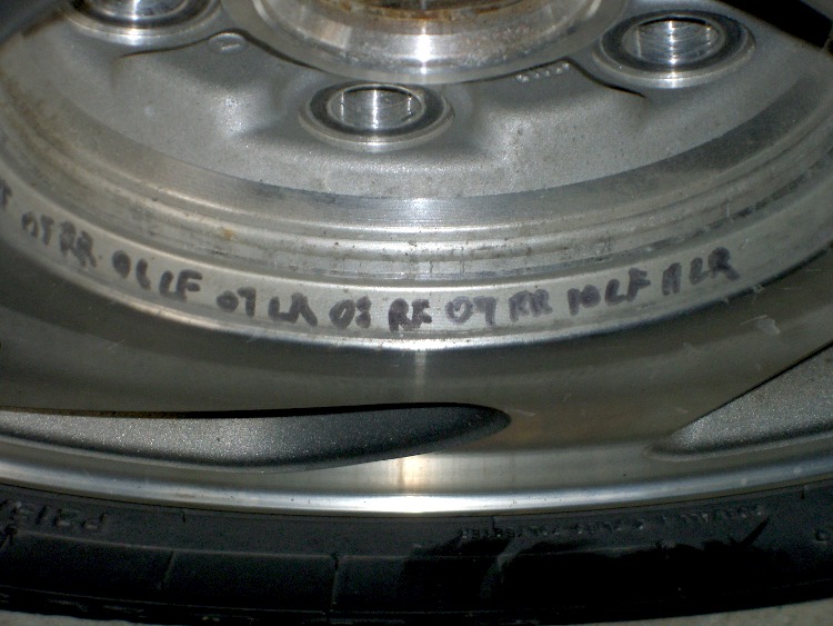
A discussion there reminded me to mention a good habit taught by my buddy Eks: when you must look something up, write the information where you’ll see it the next time you need it.
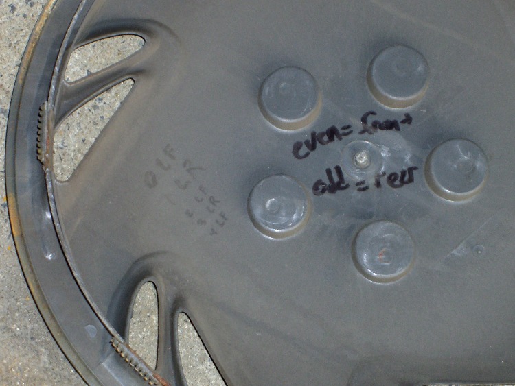
So, for example, each of the van wheels sports its own tire-rotation schedule inside the cover. When it’s time to swap tires in early spring and late autumn, I pry the cover off, read where the tire should go, and do the deed. I write ’em down four or five years at a time, so there’s not much thinking involved.
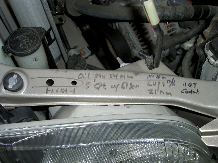
The engine compartment has all the most-often-used wrench sizes and capacities.
I write the oil change & inspection info in the maintenance schedule booklet that came with the van, although after a decade that’s pretty much full up.
Our daughter snagged some tchotchkes from a high-school career fair, including one that she instantly recognized as a flamethrower: Antibacterial Hand Sanitizer Spray, 62% Ethyl Alcohol plus some other junk, in a handy pump-spray container. Heck, it even says
Warnings Flammable. Keep away from open flame. Keep out of reach of children.
I was so proud of her…
Flare3.gif
After homework, she stuck a candle atop the garbage can by the garage and fired off a few shots while I ran the camera. Here’s the best one, converted to a low-speed animated GIF.
We’re pretty sure that’s Sweet Babby Jeebus™ in the next-to-last frame of the flare. Maybe Madonna. Could go either way.
Much as with the “movies” I made for trebuchets and tree frogs, I used ffmpeg to shred the camera’s mpg movie into separate jpg images, some bash to select the frames, then convert to stitch them back together into a gif.
The general outline:
mkdir Frames
ffmpeg -i mov04990.mpg -f image2 Frames/frame-%03d.jpg
cd Frames
mkdir flare3
for f in `seq 760 780` ; do cp frame-${f}.jpg flare3 ; done
cd flare3
convert -delay 50 frame-* Flare3.gif
If my bash-fu was stronger, I could feed the proper file names directly into convert without the copy step.
Now, kids, don’t try this at home. At least not without responsible adult supervision…