Ed Nisley's Blog: Shop notes, electronics, firmware, machinery, 3D printing, laser cuttery, and curiosities. Contents: 100% human thinking, 0% AI slop.
After few days in the Drive Blue Streak wheelchair, I finally lubricated the foot rest pivots:
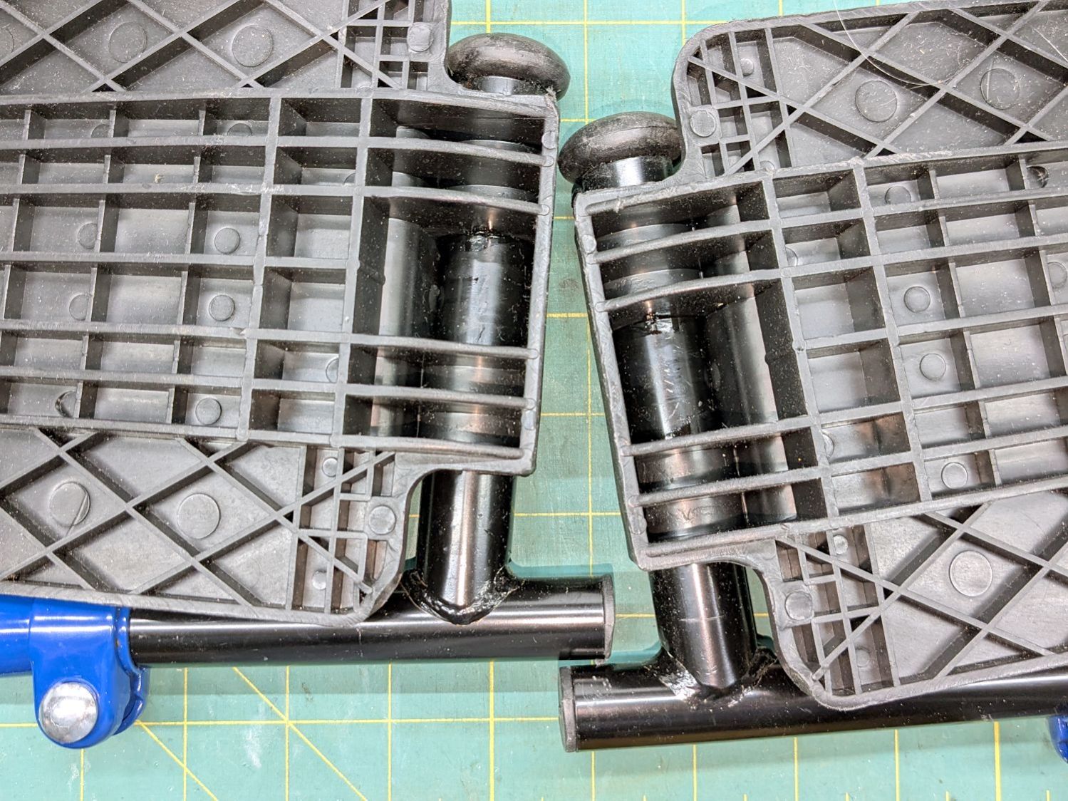
Drive wheelchair foot rest lubrication
The complex molded rests gripped their metal tubes so tightly as be nearly immovable, but one drop of Kroil at the four obvious spots let them turn much more easily.
The flange overlapping the upright tube along the bottom of the picture hits the short protrusion and holds the rest parallel to the floor. A screw at the plastic cap near the top keeps the rests from working their way too far from the upright tube.
I can make it to the Basement Shop™ and back, paying careful attention to detail.
Mary wanted a Ruler Foot (a.k.a. Handi Feet Sure Foot) on her Handi Quilter HQ Sixteen sewing machine, which required removing the original foot, installing the Handi Feet Conversion Kit, then adjusting the foot height above the needle plate:
The Conversion Kit instructions repeatedly recommend hauling the machine to your local Handi Quilter authorized dealer / repair center, which would be an hour’s drive away. Suffice it to say I’m both authorized by a suitable authority and a dab hand with a hex wrench: I can do this thing.
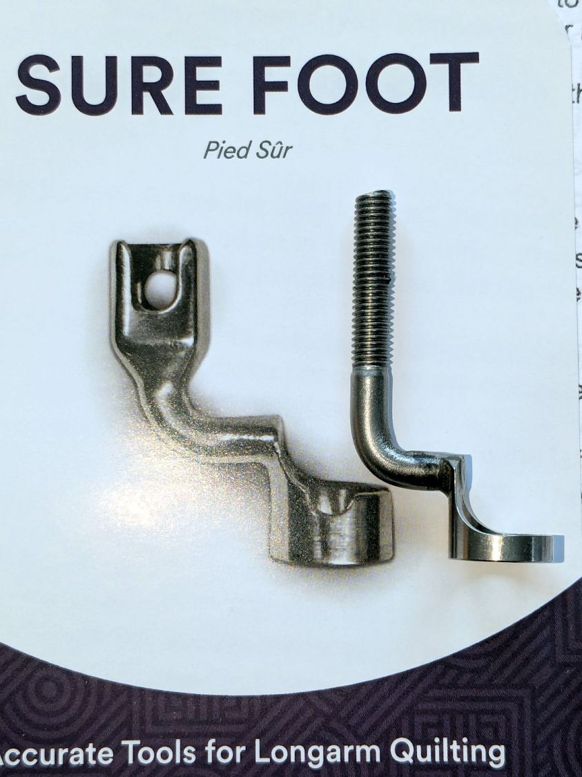
The original foot is a welded assembly with an M5×0.8 screw thread matching the leftmost (darker) rod on the machine:
HQ Sixteen Handi-feet conversion – original foot
It’s sitting atop the label of the Sure Foot kit with a picture of the ruler foot.
Although the instructions suggest you can install the conversion kit without removing the machine cover, I wanted to see what was going on in there and verify everything fit properly:
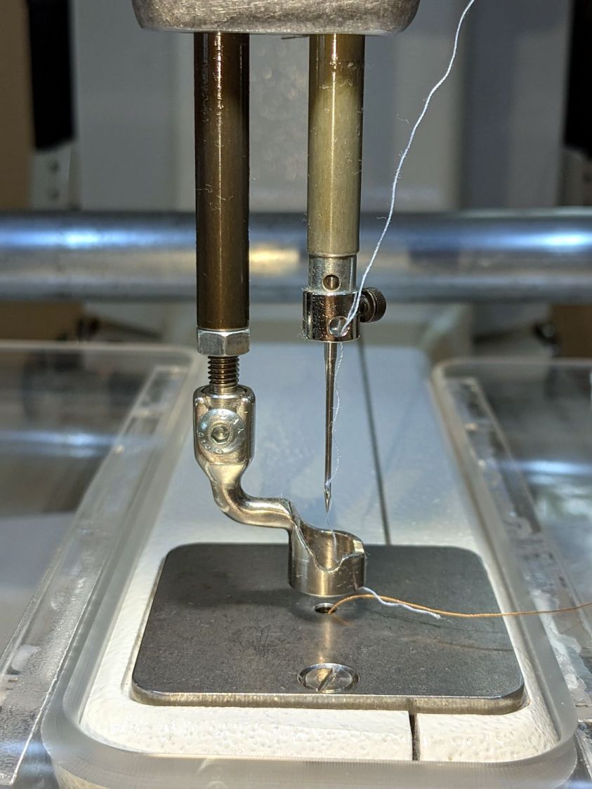
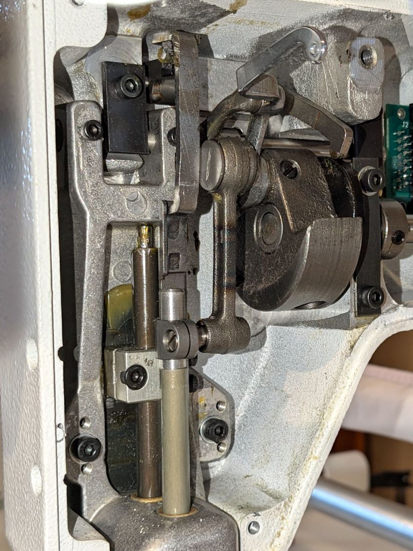
HQ Sixteen Handi-feet conversion – foot rod clamp
As above, the foot / adapter screws into the left rod, with the rectangular aluminum clamp attached to the follower riding the cam near the top of the machine. The rod slides on the greasy pin absorbing the torque from the follower.
I had to loosen the clamp, slide the rod upward, unscrew the original foot, install the adapter, adjust the rod position for the proper 0.5 mm spacing between ruler foot and the needle plate at bottom dead center, then tighten the screw. The disturbed grease above the block reveals I moved the rod upward about 8 mm through that block during the process; it now sits lower, just a few millimeters above where the factory tech assembled it for the original foot.
The top photo shows half a dozen threads between the top of the adapter and the bottom of the jam nut. Without adjusting the rod position in the clamp, the adapter screw threads are the only way to adjust the foot-to-plate space: each full turn moves the foot 0.8 mm. I screwed the adapter completely into the rod, then backed it out three turns to leave enough adjustment for other feet and fabrics.
The machine cover has a hole providing access to the clamp screw, so, in principle, you can stick a hex wrench in there to loosen / tighten the clamp while making fine adjustments in the foot position, all without removing the cover. If one full turn of the adapter doesn’t set the right position, I highly recommend removing the machine cover to see what you’re doing.
We then installed the Ruler Base on the machine, which required removing the preinstalled Medium fuzzy spacer strips, and all’s well that ends well.
The ↓ (“down”) button on one of our lift chairs stopped working, although the ↑ (“up”) button worked fine and, as you’d expect, verifying this problem left the chair in a rather awkward position.
The usual power cycle and unplugging / replugging the control had no effect.
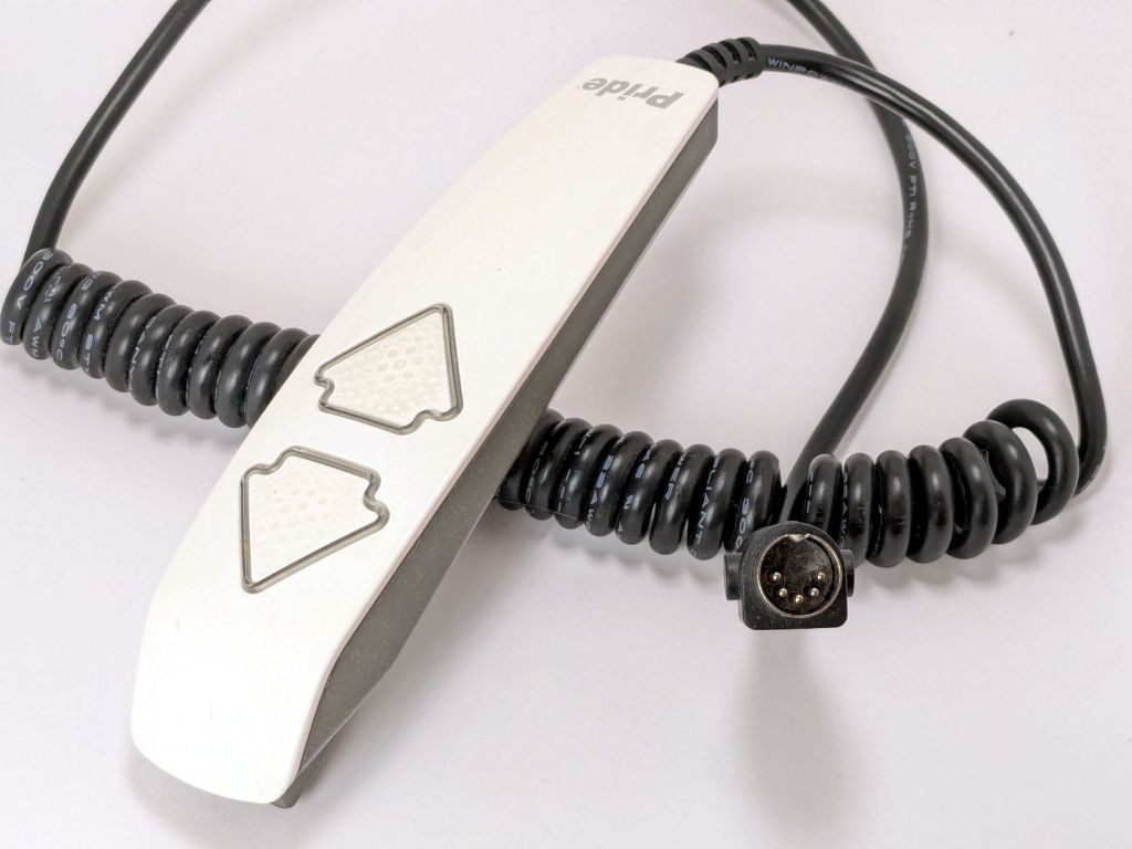
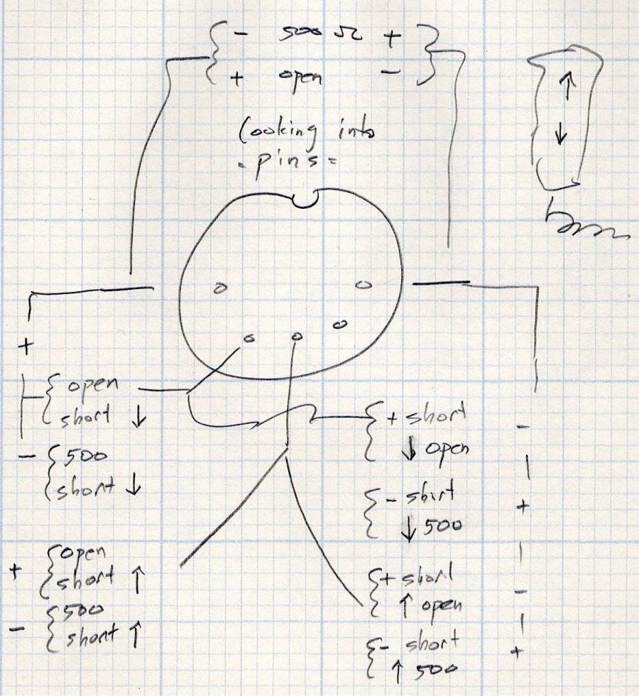
This control is the one I couldn’t pry apart to dim its LEDs, so I tried various combinations of pins until this scribble emerged:
Pride Lift Chair – control pinout doodle
I have no idea of the correct pin numbering, but the scribble looks into the connector pins with the keyway on top:
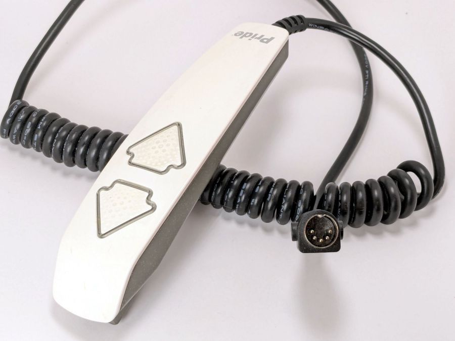
Pride lift chair control
The more intricate control for the other Pride lift chair has only four pins in its connector, so I couldn’t just swap them to see what happened.
The polarities are for the continuity / resistance test probes.
The takeaway: The two buttons did similar things to two different connector pins, so the control seemed to be working correctly and the fault lies elsewhere.
The control sports a USB jack for powering / charging your favorite device and I’m reasonably sure the control has a microcontroller tucked in there for good reason, implying the circuitry is surely more complex than maybe a rectifier bridge and some resistors.
So I shoved the chair into the middle of the room, deployed some test equipment, reconnected the control, plugged the chair power supply into the outlet strip, and … of course both buttons worked perfectly.
Soooo the chair is back in place and we’ll see what happens next.
Speaking of Heisenbugs, the HQ Sixteen continues to work fine, too.
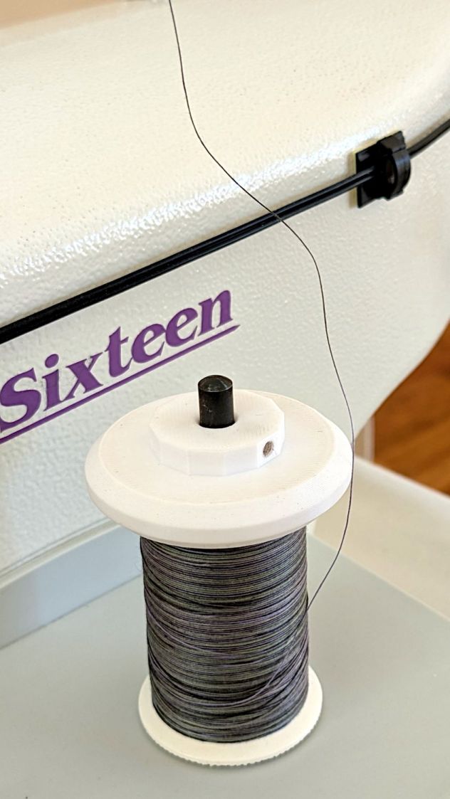
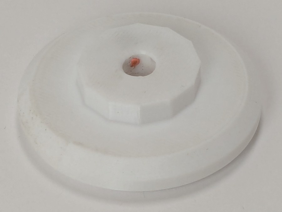
The HQ Sixteen consumes thread at a prodigious rate, so it’s set up for large thread cones. Mary sometimes uses ordinary thread spools (leftovers from sewing projects) for short practice sessions and wanted an adapter to hold the little things in place:
Thread spool adapter – installed
Those of long memory should recall previous adapters for both sizes and their notes about how thread should peel off spools & cones. I considered an adapter with a horizontal spool axis, but contemporary machines apparently don’t bother with such niceties. We may need a right-angle adapter to let the thread pull off from the side, but we’ll start simple and fix it if needs be.
The small crosswise hole in the hub gets an M3 setscrew pushing a rubber pellet slightly into the central bore for a friction fit. The OpenSCAD code can distribute any number of such holes, but one seemed entirely adequate.
The code shrinkwraps a hull() around two cylinders to create the tapered sides, thus giving the thread less surface to drag across. I have PrusaSlicer set to produce scarf joints around the perimeter and the edges came out surprisingly smooth, with only one rough spot requiring deft Xacto knife work. It’s made from white PETG for a smoother finish than PETG-CF.
The OpenSCAD code consists mostly of constants defining the various physical measurements and a few lines assembling the model:
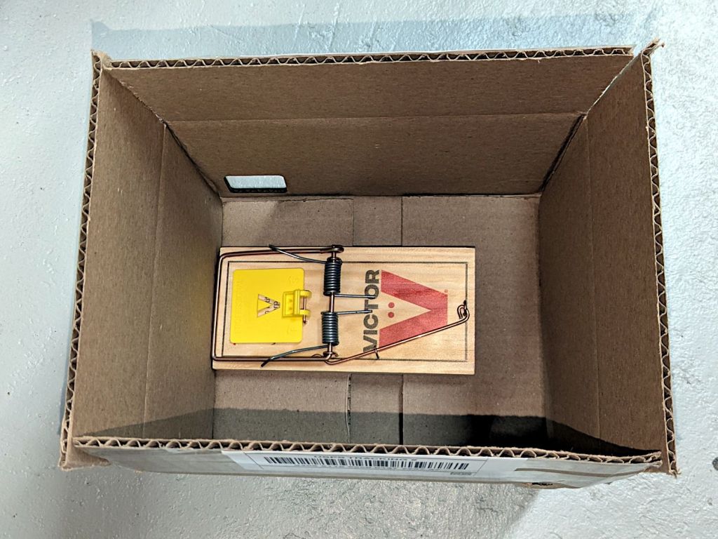
Although we had considerable success trapping voles during the last half of the 2024 gardening season, Mary found a description of what might be a better technique: a box with small entrance holes taking advantage of rodent thigmotaxis: their tendency to follow walls. The writeup shows nicely made wood boxes, but I no longer have machinery capable of cutting arbitrarily large wood slabs into pieces.
I do, however, have a vast pile of cardboard boxes:
Vole Box – large
That’s a rat-size trap.
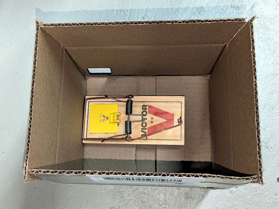
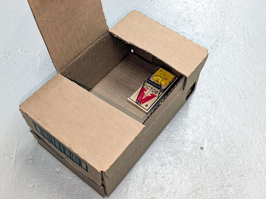
A smaller box has room for two mouse-size traps (one hidden on the left):
Vole Box – small
The general idea: plunk the box in a garden plot, arm the trap(s), close the lid, and eventually a vole will venture inside, whereupon wall-following leads to disaster. Apparently bait is optional, as wall-following inevitably takes them over the trap pedal. I won’t begrudge them a walnut or two, should bait become necessary.
Cardboard is obviously the wrong material for a box in an outdoor garden, but I figure they’ll survive long enough to show feasibility and I can deploy a lot of small boxes before having to conjure something more durable.
Yes, those are laser-cut rounded-rectangle holes: 30 mm and 40 mm, assuming voles care about such things.
It has always seemed like a Bad Idea™ to run indoor air through the clothes dryer and dump it overboard, particularly during days when the indoor air has been painstakingly (perhaps expensively) heated or cooled. The dryer now lives in a separate room with two doors, so we can close it off from the rest of the house and let it inhale outdoor air through the screen on the storm door.
Except in winter, when a glass pane covers the screen. Propping the door open just a bit is unattractive, because an open door seems like an invitation to any field mouse looking to upgrade its domicile.
Given that the dryer exhausts through a length of 4 inch flexible duct, I figured a similar vent, facing inward, mounted on the storm door would admit enough air to keep it happy. Keeping insects and adroit mice out requires a screen:
Dryer Inlet Vent – filter retainer
After taking that picture, I rammed four threaded brass inserts into the holes, thereby eliminating the need for a handful of washers and nuts, some of which were absolutely certain to disappear through gaps in the deck.
The two blue-gray rings are PETG-CF:
Dryer Inlet Vent Filter Retainer – solid model
The small split makes the inner retainer just springy enough to fit over the two small tabs normally locking a dryer hose in place.
The OpenSCAD code gloms a few shapes together:
include <BOSL2/std.scad>

/* [Hidden] */

VentID = 102.0;     // diameter at base of vent opening
VentOD = 107.5;

OpenAngle = 3;

LipWidth = 3.0;         // lip around vent opening
LipThick = 7.5;

StrutWidth = 2.5;       // wide enough to hold filter
StrutThick = 3.0;       // tall enough to be rigid
NumStruts = 3;

Protrusion = 0.1;

NumSides = 360/6;

$fn=NumSides;

//----------
// Build it

union() {

    linear_extrude(LipThick)
        ring(NumSides,d1=VentID - 2*LipWidth,d2=VentID,angle=[OpenAngle/2,360-OpenAngle/2],spin=270);

    linear_extrude(StrutThick) {
        circle(r=StrutWidth);

        for (i=[0:(NumStruts-1)]) {
            a = 90 + i*360/NumStruts;
            zrot(a)
                right(VentID/4)
                    square([VentID/2 - LipWidth/2,StrutWidth],center=true);
        }
    }

    linear_extrude(LipThick)                // outside trim ring
        ring(NumSides,d1=VentOD,d2=VentOD+2*LipWidth);
}
The overall union() keeps PrusaSlicer from identifying the thing as a multi-material model. Apparently, it still looks enough like a logo to qualify for special treatment, but I fought it to a standstill.