Ed Nisley's Blog: Shop notes, electronics, firmware, machinery, 3D printing, laser cuttery, and curiosities. Contents: 100% human thinking, 0% AI slop.
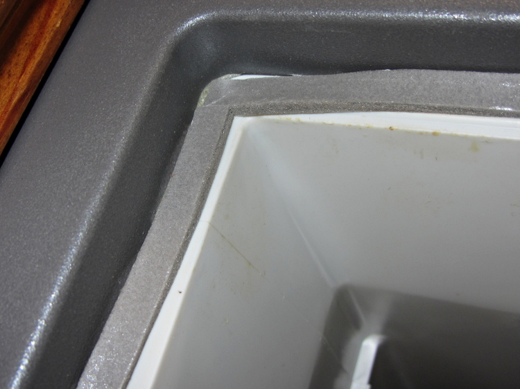
A bit of rummaging in the Big Box o’ Weatherstripping produced the stub end of a spool bearing 1/4 x 1/8 foam tape that exactly fills the gap between the Basement Safe’s door and liner:
Basement Safe – Foam door seal – latch side
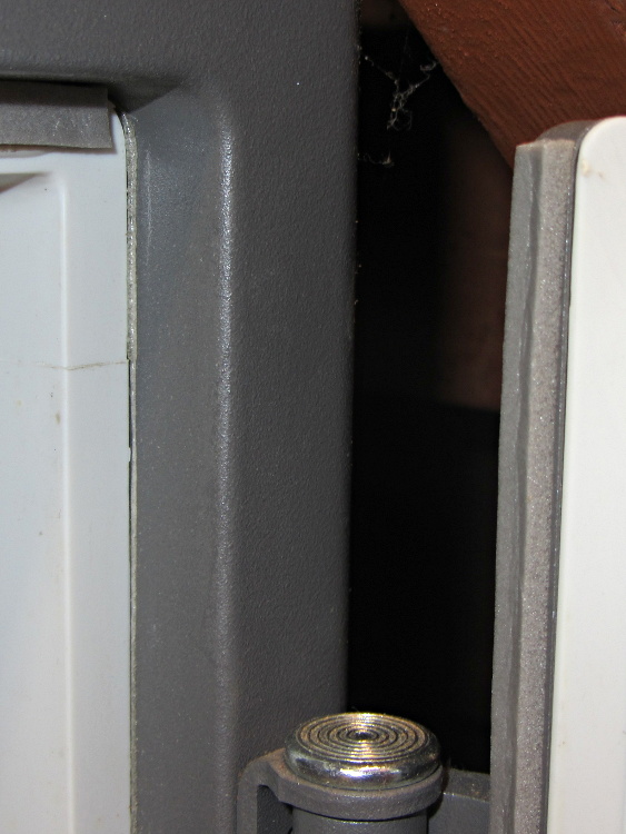
The hinge side of the door has tape between the door liner and the safe wall, because that closes in compression rather than shear:
Basement Safe – Foam door seal – hinge side
There should be a big bump in the humidity record marking that installation, but I don’t expect any immediate difference. If the silica gel lasts more than two months, I’ll consider it a win.
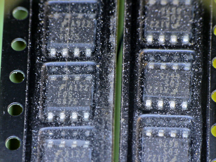
So I picked up a lot of 20 p-channel MOSFETs from the usual eBay supplier in China, which arrived in good order. As is often the case, the SOIC chips are in snippets of tape-and-reel carrier, but this tape looked decidedly odd:
eBay FDS6675 Tape Cover Contamination
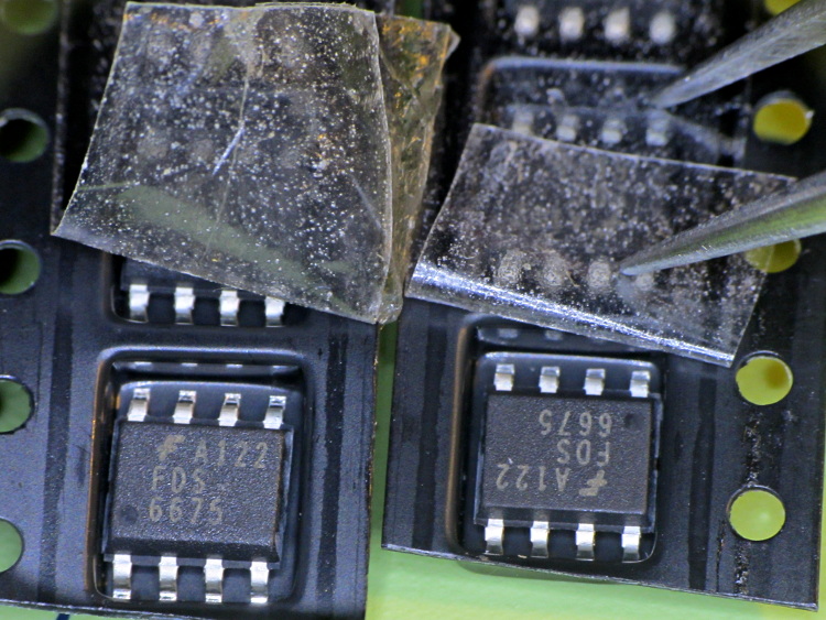
Peeling back the tape shows that the crud is just on (or perhaps inside) the tape, not on the ICs or inside the carrier pockets:
Some of those specks are dirt, some seem to be bubbles, other are just, well, I don’t know what they might be. Maybe they were having a bad day in the tape factory?
One might reasonably conclude the chips aren’t in their original carrier…
I must gimmick up a quick test to verify that the chips behave like p-channel MOSFETs, instead of, oh, solid plastic; that Fairchild logo looks a bit grotty, doesn’t it?
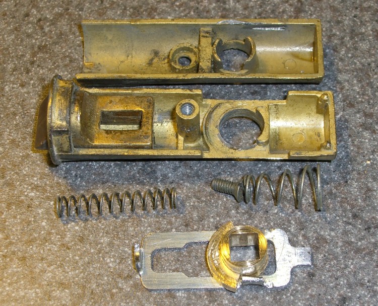
The discussion following that post on getting feature coordinates from an existing part reminded me of an old project that I’d written up for Digital Machinist: making repair parts for the half-century old storm doors on our house. Here’s the whole latch, with a replacement drawbar and cam:
Latch Assembly
The other side of the drawbar and cam:
Door Latch Parts
An early version of the drawbar that engages the latch strike and gets pulled by cam:
New and Old latch pulls
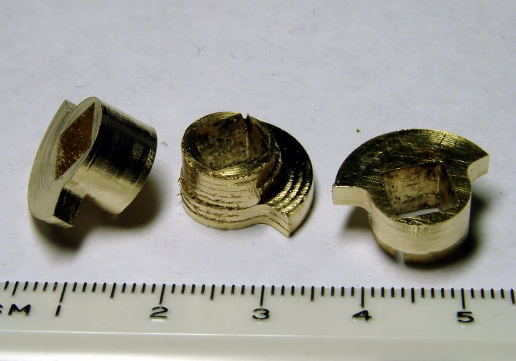
Three iterations on a cam; the messed-up one in the center, IIRC, helped track down an EMC2 bug:
Latch Cams
Now that I look at it again, there’s nowhere near enough meat around that square hole for a 3D printed plastic part… so the notion of printing the complex part of the cam and adding wear bars along those ears just isn’t going to work.
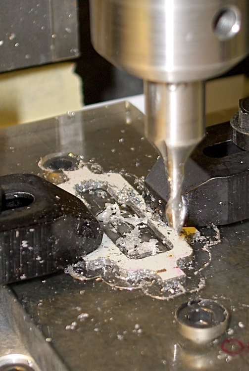
I made a fixture for the Sherline CNC mill to hold the drawbar for inside milling:
Latch pull – Inside milling
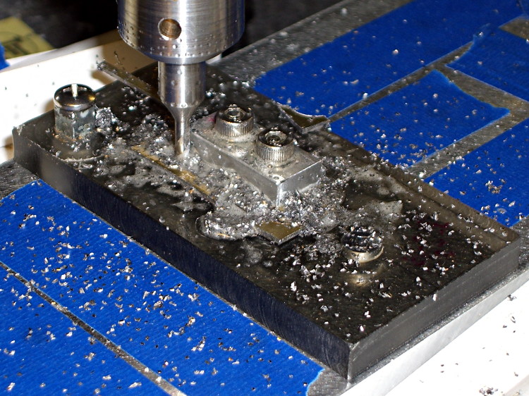
Then a block screwed down in the middle clamps the drawbar in the same place for outside milling:
Latch pull – Outside milling
The square post in the left rear corner holds the cam:
Latch Cam – First Attempt
Note that I had to file the square hole before milling the cam shape, which meant that if the CNC process screwed up, all that handwork went into the show-n-tell bin… which I’m not going to show you.
I used an early version of the grid-overlay technique to map out the drawbar coordinates; this was an illustration for the column:
A bag of 50 cheap Hall effect sensors arrived from the usual eBay vendor, who was different from all previous eBay vendors (if in name only). Passing 124 mA through the armored FT50 toroid with 25 turns of 26 AWG wire, we find this distribution of bias points, measured as the offset from the actual VCC/2:
eBay 49E Hall Effect Sensor Bias Histogram
The bias point is actually referenced to the negative terminal (usually ground) with a ±0.25 V variation around the nominal. SS49 sensors run about 0.5 V below VCC/2 (2.25 V with a 5 V supply), SS49E sensors at 2.5 V with a tighter VCC limit that suggests you better stay pretty close to 5.0 V.
Allowing for the fact that I really don’t have good control over the actual magnetic field, the gain distribution seems tight:
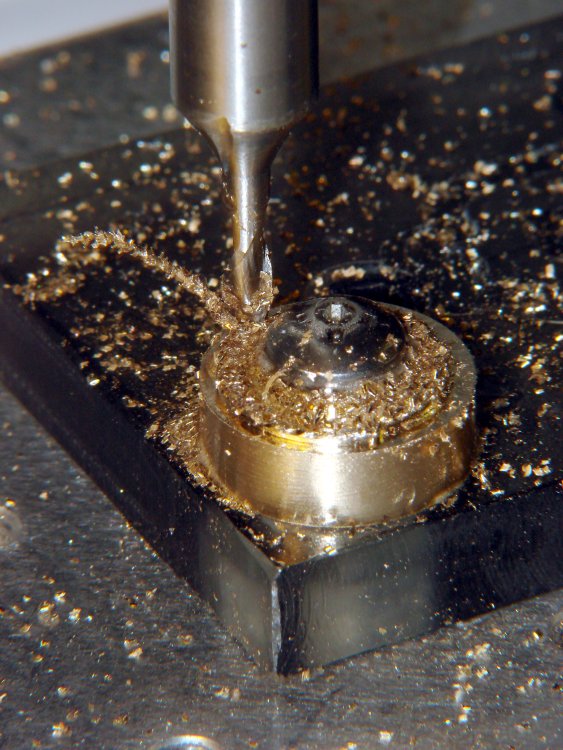
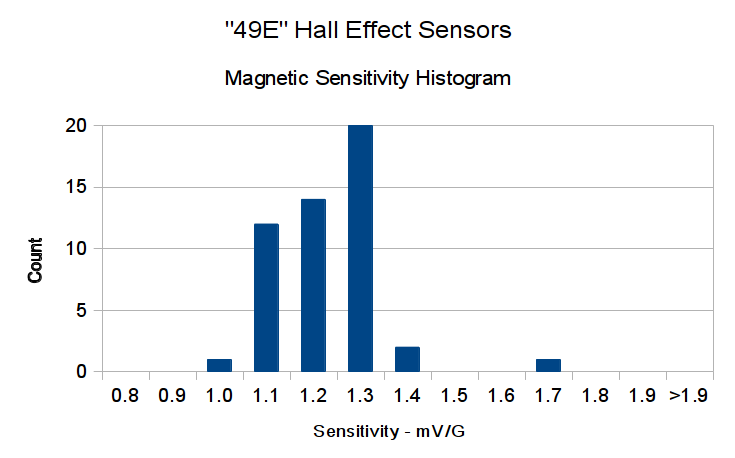
eBay 49E Hall Effect Sensor Sensitivity Histogram
You’ll recall the Genuine Honeywell sensor specs:
SS49 – nominal 0.9 mV/G, limits 0.6 to 1.25 mV/G
SS49E – nominal 1.4 mV/G, limits 1.0 to 1.75 mV/G
The gain is roughly half that of the previous “49E” sensors, confirmed by sticking one of them this field. I don’t know which is more accurate, but these have a much prettier distribution.
So this lot resembles 49E sensors in both bias and gain.
Given the bias variation, though, it’s obvious that a DC application must measure the zero-field output and apply an analog offset to the amplifier, because a twiddlepot setting won’t suffice. Most likely, you’d want to update the offset every now and again to compensate for temperature variation, too.
Tossing the outliers gives an average gain of 1.17, which would give results within 10% over the lot. Given that you don’t care about the actual magnetic field, you could calibrate the output voltage for a known input current and get really nice results.
If you were doing position sensing from a known magnet, you’d want better control of the magnetic field gradient.
We spotted this crumpled front end at a local repair shop:
Deer crash damage – overview
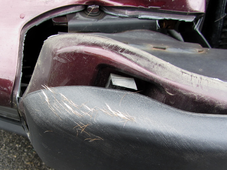
A closer look at the bumper tells the tale:
Deer crash damage – hair detail
Pop Quiz: estimate the total cost of that collision, including the overhead of having to deal with the insurance company and arrange alternate transportation for a week or two.
Essay: explain why it’s possible for someone to insist that both deer and humans are better off under these conditions.
In this area, vehicles serve as the top predator for deer…
Mary’s been picking blueberries and freezing them for winter treats, a process that involves inspecting each berry laid out on the tray.
This one failed QC:
Blueberry with eggs – overview
A closer look shows some remarkable structures:
Blueberry with eggs – detail
Unfortunately, they’ll probably turn into Brown Marmorated Stink Bugs. This is not a Good Thing, because those stink bugs will devastate fruit harvests, including all the apple orchards along the entire Hudson Valley, over the next few years.
They may be Predatory Stink Bugs, which would be unusual in Dutchess County, but not nearly so awful.