Ed Nisley's Blog: Shop notes, electronics, firmware, machinery, 3D printing, laser cuttery, and curiosities. Contents: 100% human thinking, 0% AI slop.
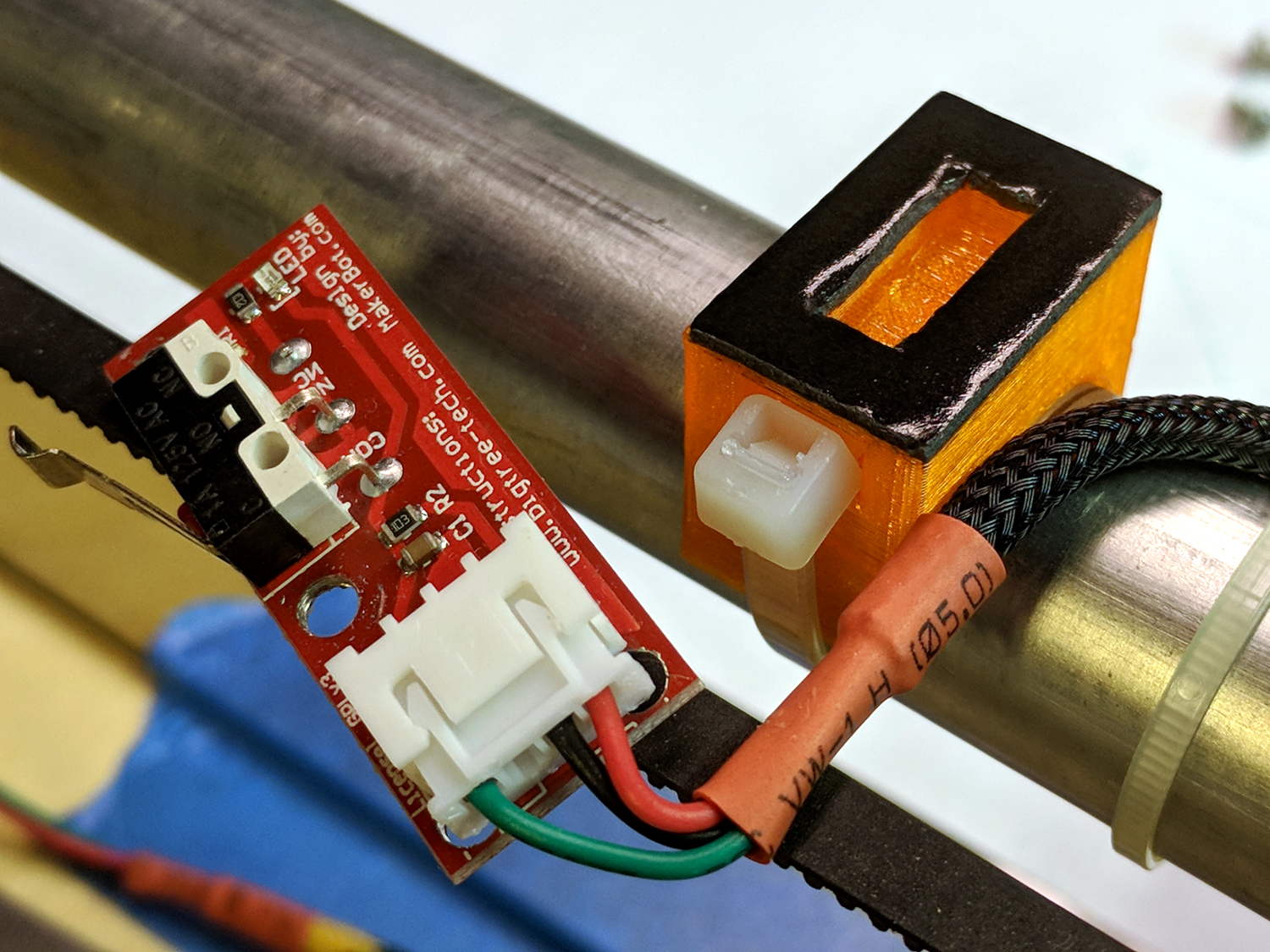
Using 3D printer style endstop switches has the advantage of putting low-pass filters (i.e. caps) at the switches, plus adding LED blinkiness, but it does leave the +5 V and Gnd conductors hanging out in the breeze. After mulling over various enclosures, it occured to me I could just entomb the things in epoxy and be done with it.
The first step was to get rid of the PCB mounting screws and use 3M permanent foam tape:
MPCNC – Epoxy-coated Endstop – Adhesive Tape
Get all the switches set up and level, mix up 2.8 g of XTC-3D (because I have way too much), and dab it on the switches until all the exposed conductors have at least a thin coat:
MPCNC – Epoxy-coated Endstop – Installed
You should use a bit more care than I: the epoxy can creep around the corner of the switch and immobilize the actuator in its relaxed position. Some deft X-Acto knife work solved the problem, but only after firmly smashing the X axis against the nonfunctional switch.
Epoxy isn’t a particularly good encapsulant, because it cures hard and tends to crack components off the board during temperature extremes. These boards live in the basement, cost under a buck, and I have plenty of spares, so let’s see what happens.
At least it’s now somewhat more difficult to apply a dead short across the Arduino’s power supply, which comes directly from a Raspberry Pi’s USB port.
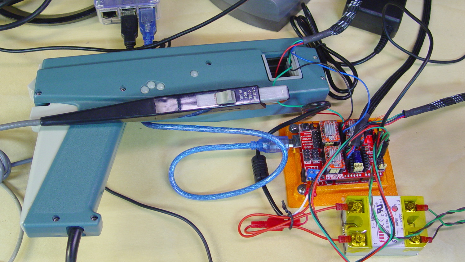
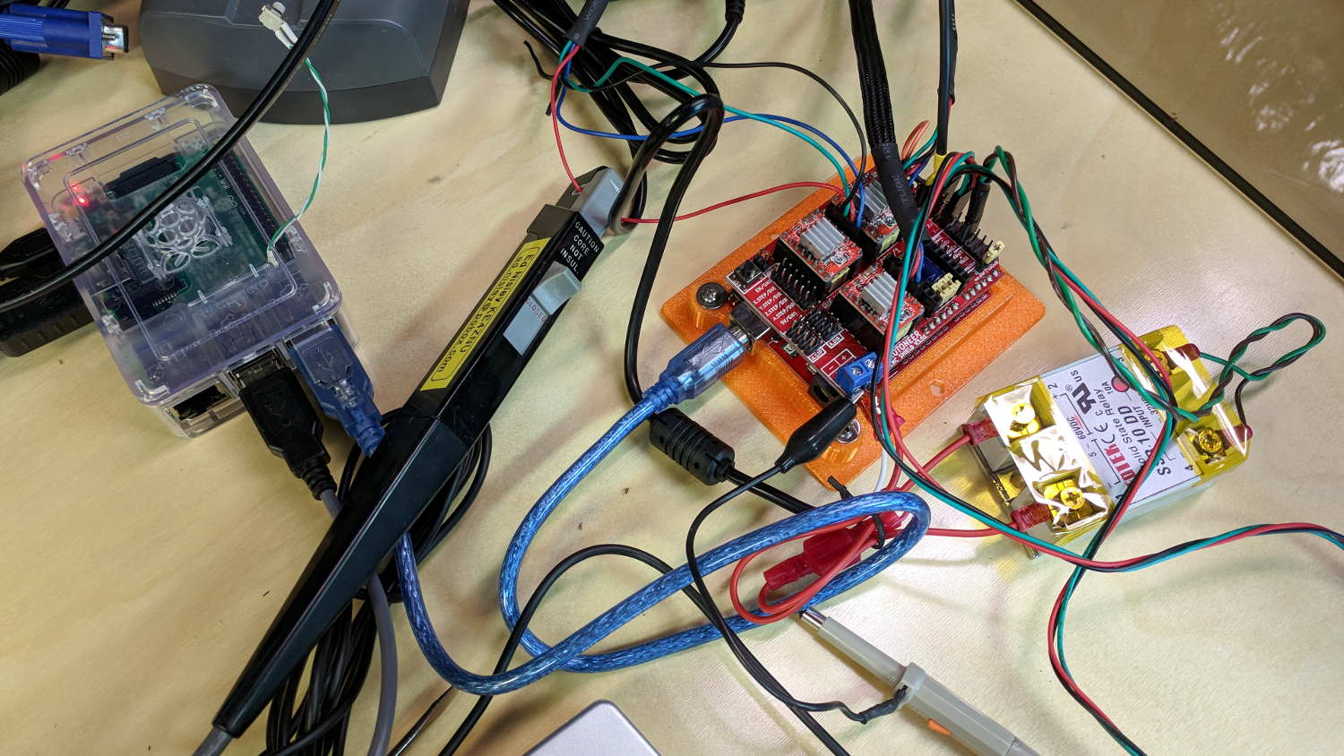
I measured stepper motor winding current with a pair of Tek Hall effect probes for future reference.
MPCNC – X Axis current measurement setup – overview
The pistol-shaped A6303 measures up to 100 A, so it’s grossly overqualified for the job. The much smaller A6302 goes to 20 A and is definitely the right hammer. The single-trace pix show 200 mA/div.
I’m using the default 12 V6 A MPCNC stepper power supply, with A4988 stepper driver boards on the Protoneer CNC Shield atop a knockoff Arduino UNO running GRBL firmware. The blue USB cable goes off to a Raspberry Pi running minicom for manual control.
All the pix use the same G-Code command: G1 X2.4 F180. Running at 180 mm/min = 3 mm/s eliminates pretty nearly all visible acceleration.
Each picture requires:
m9 to disable stepper power
Remove X axis A4988 driver board
Set jumpers to select new microstep mode
Reinstall driver board
Change GRBL $100 step/mm setting to match jumpers
Ctrl-X = reset GRBL
$x = unlock
m8 = enable power
Enable scope trigger (single-trigger mode)
g1x2.4f180 motion for next image
x0 = return to origin
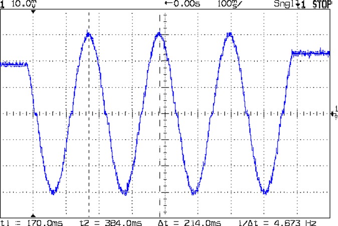
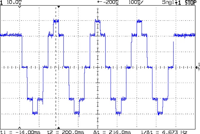
With the A4988 stepper driver in 16:1 microstep mode:
MPCNC g1x2.4f180 – 16 ustep – 200 mA-div
Notice how some of the microsteps aren’t particularly crisp, notably around the zero crossings. I think the relatively low 12 V supply doesn’t give the A4988 enough control authority to boss the current around, resulting in difficulty holding the current setpoint, even at low speed:
MPCNC X 10mm 60mm-s 500mA-div
More on that problem in a while.
In 8:1 microstep mode:
MPCNC g1x2.4f180 – 8 ustep – 200 mA-div
In 4:1 microstep mode:
MPCNC g1x2.4f180 – 4 ustep – 200 mA-div
In 2:1 microstep mode:
MPCNC g1x2.4f180 – 2 ustep – 200 mA-div
And, a rarity in modern times, both windingsat 500 mA/div in full step mode:
MPCNC g1x2.4f180 – 1 ustep – dual 500 mA-div
The A4988 driver reduces the peak current to 1/√2 of the stepped sine wave peak to maintain the same average power dissipation and torque. For reasons I cannot explain, the full-step move takes far less time than the others; it must have something to do with how GRBL computes the average speed. It sounds like a robotic woodpecker hammering on the MPCNC’s frame, so I flipped back to 16:1 microstep mode after taking that picture.
GRBL responds to critical errors by disabling its outputs, which seems like a useful feature for a big-enough-to-hurt CNC machine like the MPCNC. Unlike the RAMPS 1.4 board, there’s no dedicated power-control pin, so I connected the Coolant output to the same DC-DC SSR I tried out with the RAMPS board:
MPCNC – CNC Shield – Power SSR
With homing enabled, GRBL emerges from power-on resets and error conditions with the spindle and coolant turned off and the G-Code interpreter in a locked state requiring manual intervention, so turning the stepper power on fits right in:
$x – Unlock the controls
m8 – Coolant output on = enable stepper power
$h – Home all axes
The steppers go clunk as the power supply turns on, providing an audible confirmation. The dim red LED on the SSR isn’t particularly conspicuous.
Turning the stepper power off:
m9 – Coolant output off = disable stepper power
I think the A4988 drivers maintain their microstep position with the stepper power supply off, because their logic power remains on. In any event, you probably wouldn’t want to restart after an emergency stop without clearing the fault and re-homing the axes.
The board has Cycle Start, Feed Hold, and Abort inputs just crying out for big colorful pushbutton switches.
Unlike the RAMPS board, the Prontoneer CNC Shield does not feed stepper power to the underlying Arduino UNO, leaving it safely powered by USB or the coax jack.
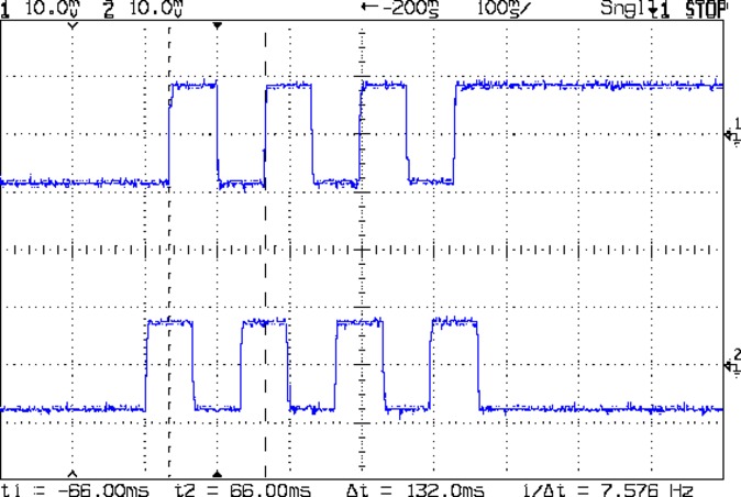
The Protoneer CNC Shield has headers for two endstops on each axis, although they’re wired to the same Arduino input pin. I installed a pair of Makerbot-style endstops on the Y axis, plugged them in, triggered one, and … the Arduino crashed. Hard. As in, a complete loss of power and reboot.
Some fiddling around produced absolutely baffling symptoms, as I replaced each endstop board and their cables to no avail.
Perusing the schematic (the “full instructions” link is dead, of course) eventually revealed the problem:
Makerbot style endstop – schematic
Got it?
Although there’s a pullup on the COM switch terminal, the switch’s NC terminal is connected to the +5 V supply, shorting across the both resistor and the LED+resistor. With two endstops in parallel, triggering one crowbars the other’s power supply to ground. I’m sure it made sense at the time, perhaps by ensuring no possible noise source could interfere with the pullup.
The solution is simple: disconnect the NC terminal from the power supply. As it turns out, the PCB layout routes +5 V on the bottom layer, up through the via around the NC switch terminal, thence to the LED and resistor, leaving only one choice:
MPCNC – dual MG endstop hack
Yup, amputate the NC terminal and be done with it.
After that, the pullup resistor lets the endstops cooperate like you’d expect: triggering either one lights up both LEDs.
The default MPCNC configuration wires the two stepper motors on each axis in series, doubling the total resistance and inductance of a single motor. The stock Automation Technology motor presents 2.8 Ω and 4.8 mH in each winding to the driver, for an L/R time constant of τ = 1.7 ms. Doubling both doesn’t change the ratio, but including the harness wiring resistance gives 1.6 ms = 9.6 mH / 6 Ω.
The default DRV8825 driver configuration uses 1:32 microstepping, which I thought was excessive. I replaced the stock RAMPS setup with a Protoneer / GRBL setup using A4988 drivers in 1:16 microstepping mode, got it configured, and made a few measurements:
MPCNC CNC Shield – Current Measurement Setup
The current probe measures the winding current in the red wire. The voltage probe at the bottom isn’t doing anything, because I ran out of hands.
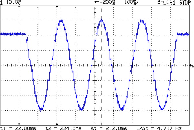
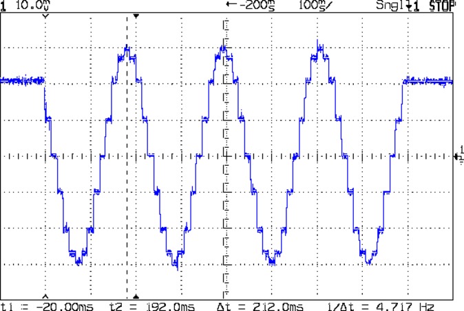
Here’s a 10 mm X axis move at 3600 mm/min = 60 mm/s:
MPCNC X 10mm 60mm-s 500mA-div
The top trace shows the winding current at 500 mA/div. The bottom trace shows the voltage applied to the winding at the A4988 driver pin.
Basically, the +12 V supply doesn’t provide enough headroom to let the driver force the required current into the winding at full speed, which is why the peak current decreases as the step rate increases and the sinusoid becomes a square(-ish) wave. The applied voltage switches rapidly to maintain the proper winding current when the axis is stationary or moving slowly (where the driver’s PWM current control works fine), but turns into a square (well, rectangular) wave as the pace picks up (and the driver loses control of the current).
The motor drives a 16 tooth pulley with a 2 mm belt pitch, so each revolution moves 32 mm of belt. With 1:16 microstepping, each revolution requires 3200 = 200 full step × 16 microstep/step pulses, which works out to 100 step/mm = (3200 step/rev) / (32 mm/rev). At the commanded speed near the middle of the trace, the driver must produce 6000 step/s = 60 mm/s × 100 step/mm, so each step lasts 167 μs, about τ/10.
In round numbers, the first full cycle on the left has a 20 ms period. Each full cycle = 4 full steps = 64 microsteps, so the belt moved (60 step) / (100 step/mm) = 0.6 mm, at an (average) speed of 30 mm/s = 1800 mm/min. The current begins to fall off by the third cycle with a 12 ms period, a pace of 50 mm/s = 3000 mm/s, and pretty much falls off a cliff by 60 mm/s in the middle.
To be fair, those are aggressive speeds for milling, but lasers and 3D printers tick along pretty quickly, so they’re not unreasonable.
“High Endurance” means it’s rated for 5000 hours of “Full HD” recording, which they think occurs at 26 Mb/s. The Fly6 records video in 10 minutes chunks, each weighing about 500 MB, call it 1 MB/s = 8 Mb/s, a third of their nominal pace. One might reasonably expect this card to outlive the camera.
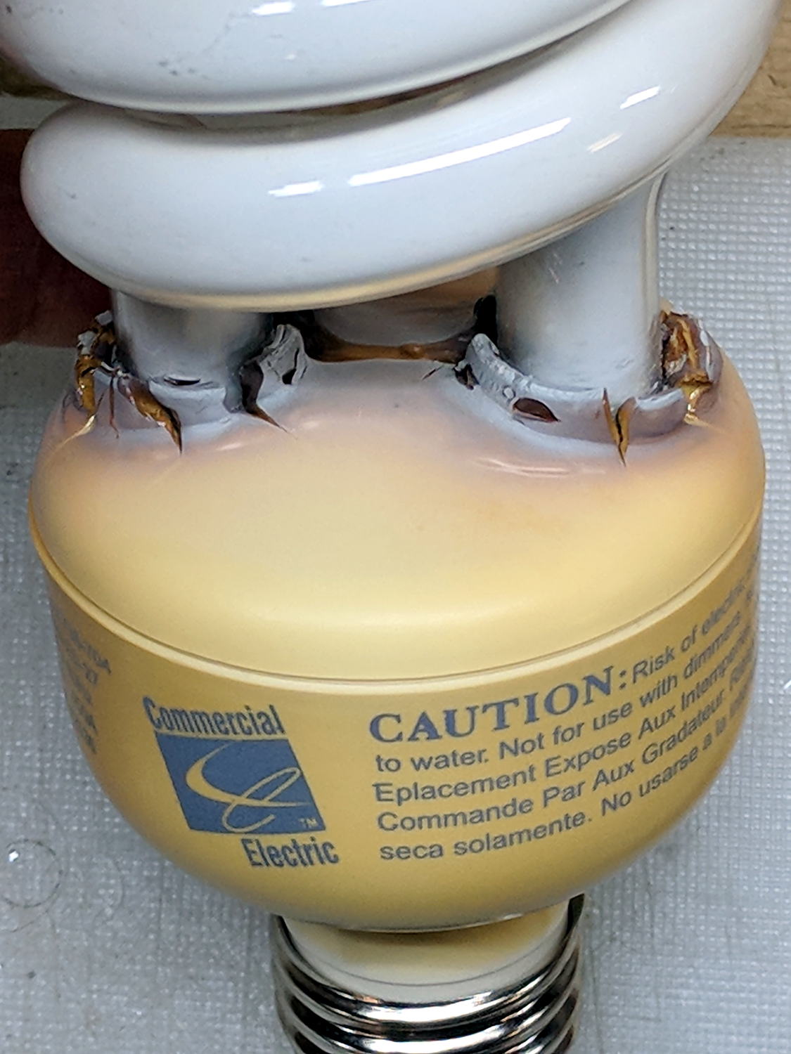
The straight-ish crack between the tube ends looks like it happened as the (yellowed) plastic ruptured and hardened.
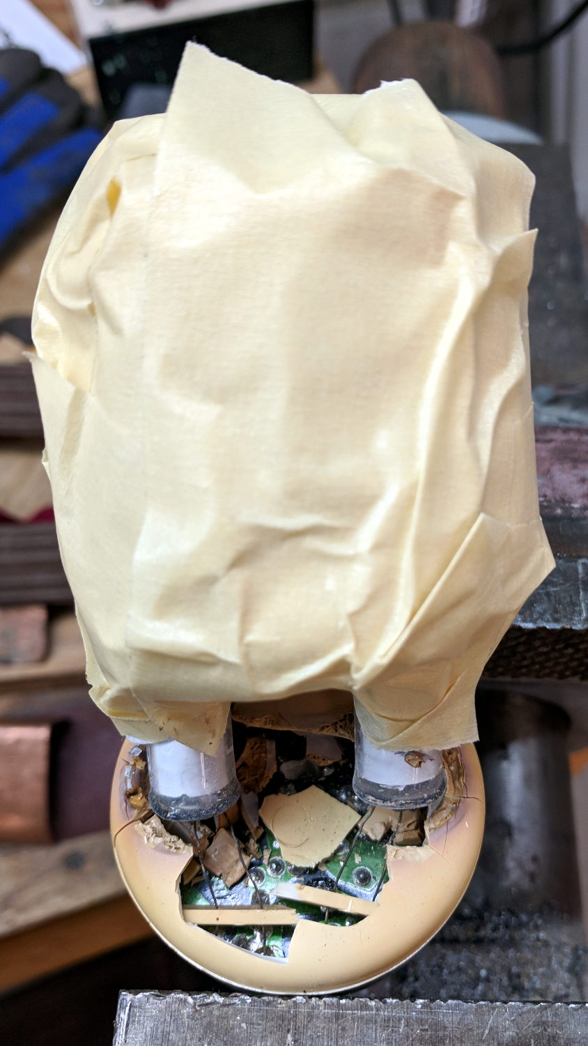
Not wanting to get a face full of glass fragments spiced with metallic mercury, I wrapped a blast shield around the spiral tube:
Failed CFL – tube wrap – shattered base
The terminal ends fit loosely in the crumbling base at the start of this operation, leaving the tube wobbling above the base. The plastic cracked as I wrapped the tube, so, for lack of anything smarter, I applied a pin punch to break away the rest of the upper base.
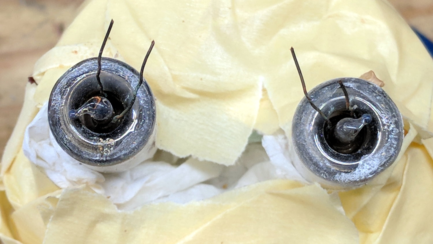
The tube doesn’t fit into a socket, of course, and terminates in four wire connections:
Failed CFL – tube terminals
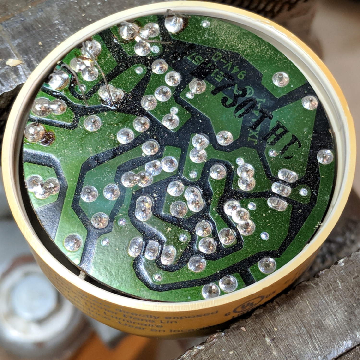
Those wires pass through notches on the edge of the PCB, bend around the board, pass through vias, and get soldered to pads. The solder side faces the tube, with all the components nestled into the base toward the screw terminals:
Failed CFL – PCB solder side faces upward
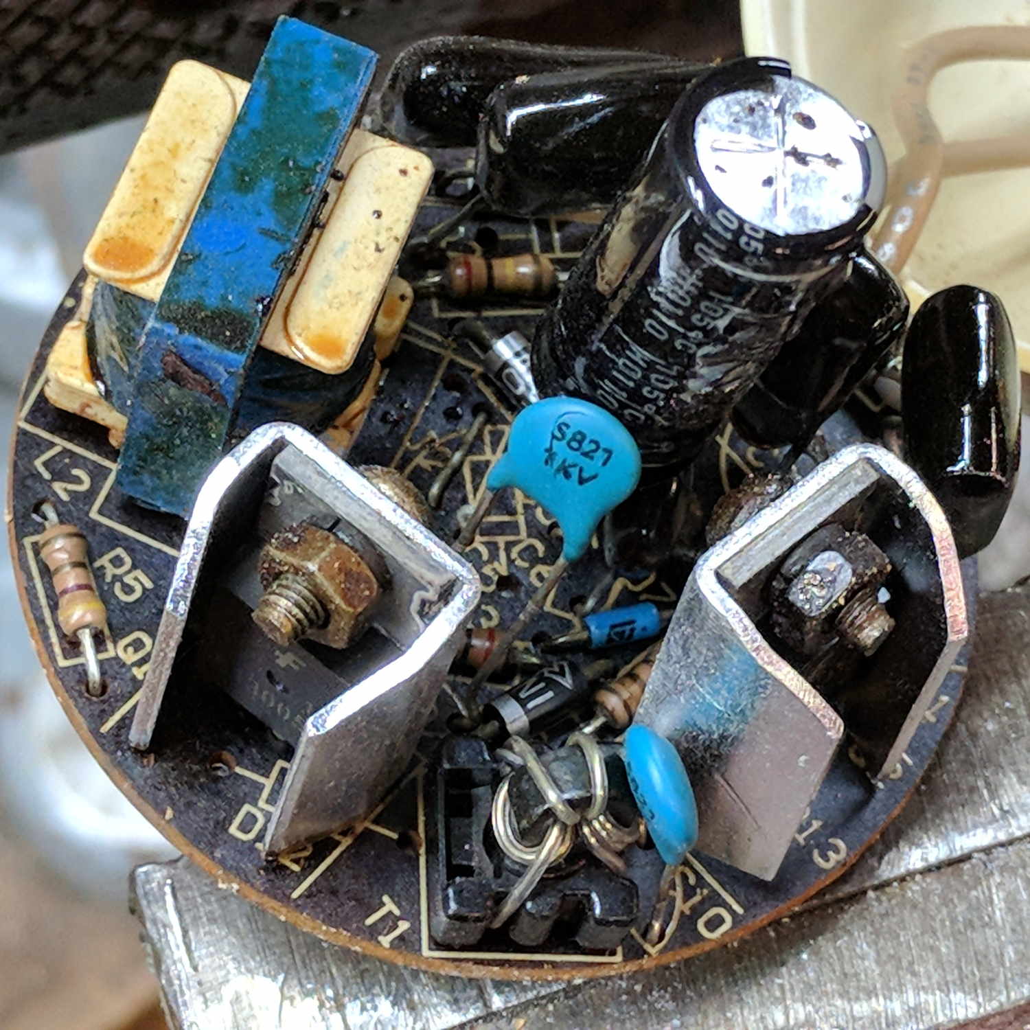
The component side sports a surprising number of parts:
Failed CFL – PCB components – 2
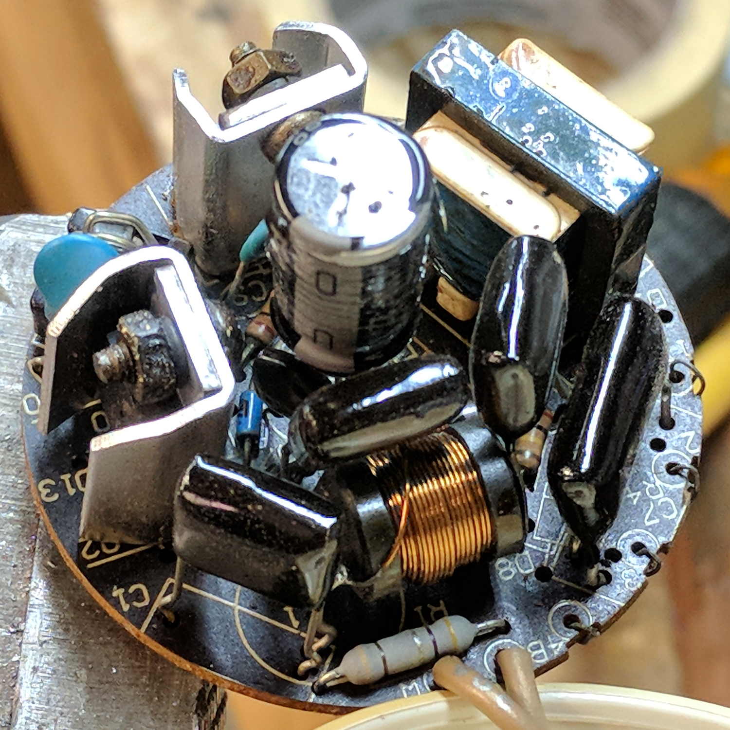
A view from the other direction, where you can see the tube wires curling around the edge:
Failed CFL – PCB components – 1
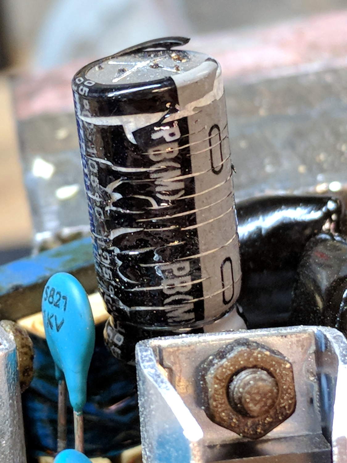
I generally harvest inductors & suchlike, but it got really really hot in there and, methinks, cooked the life out of the parts:
Failed CFL – overheated capacitor
The PCB date code stamp could be “730”, suggesting either 1997 or 2007. In any event, it’s been a while.
I hope LED bulbs outlast these things, but I have my doubts …