Ed Nisley's Blog: Shop notes, electronics, firmware, machinery, 3D printing, laser cuttery, and curiosities. Contents: 100% human thinking, 0% AI slop.
The volume control wart pod on the cable of my old and longsuffering Lenovo headset had been dropping out the right channel for a while, eventually prompting me to discover it comes apart by simply pulling on the halves:
Lenovo Headset – control pod
There being no way to get closer to the open-frame volume pot’s innards, I eased a drop of DeoxIT Red along its edge (upper in the photo), slipped another drop into what’s presumably the wiper opening in the knob, and ran it through enough cycles to spread the juice evenly.
Reassemble in reverse order and It Just Works™ again.
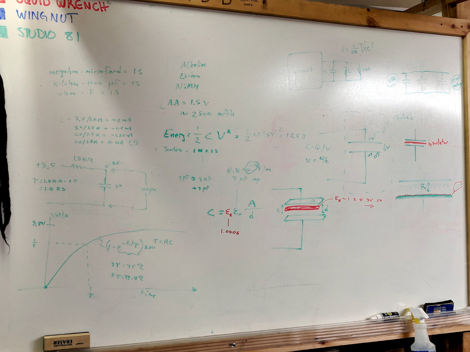
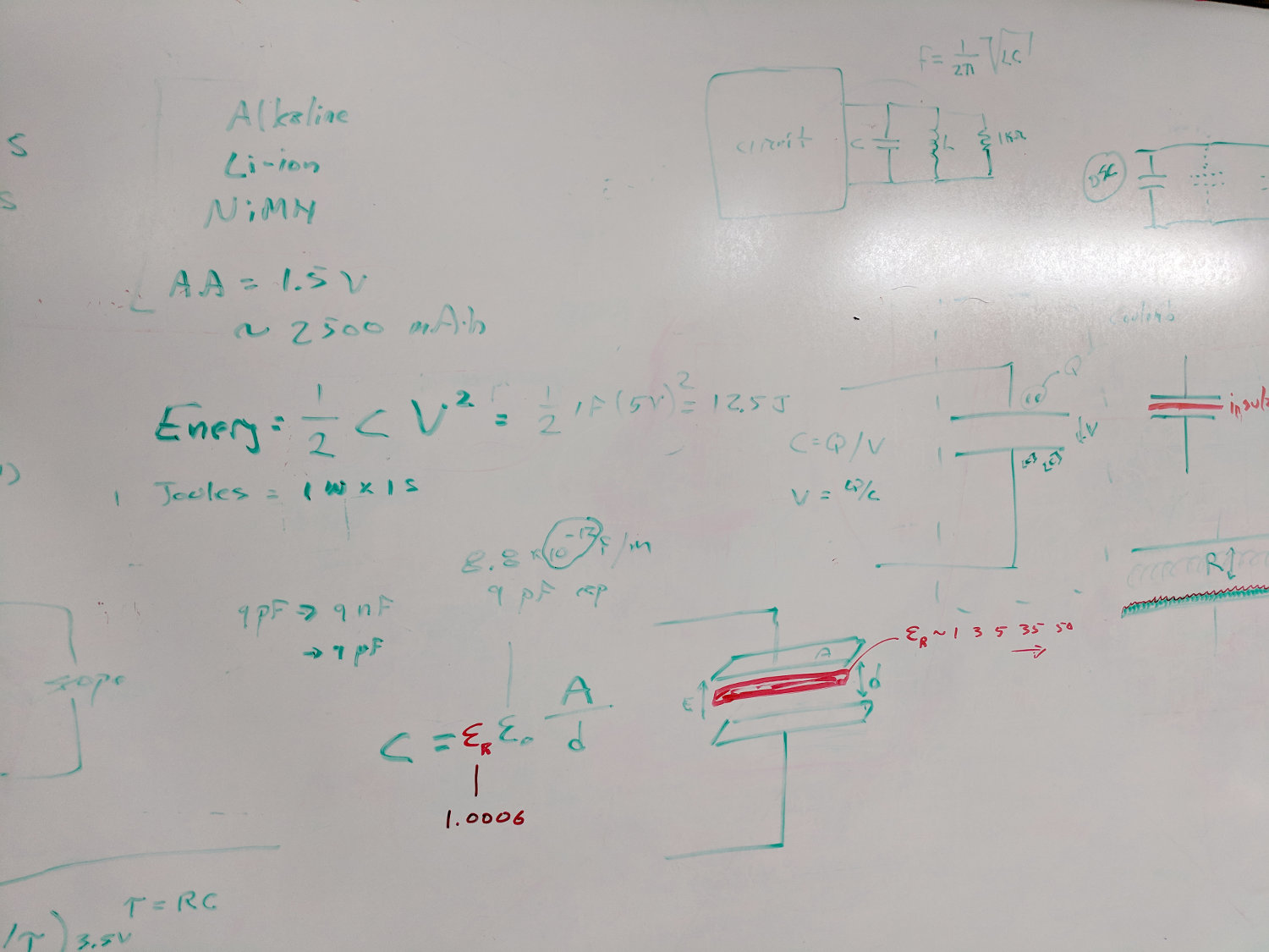
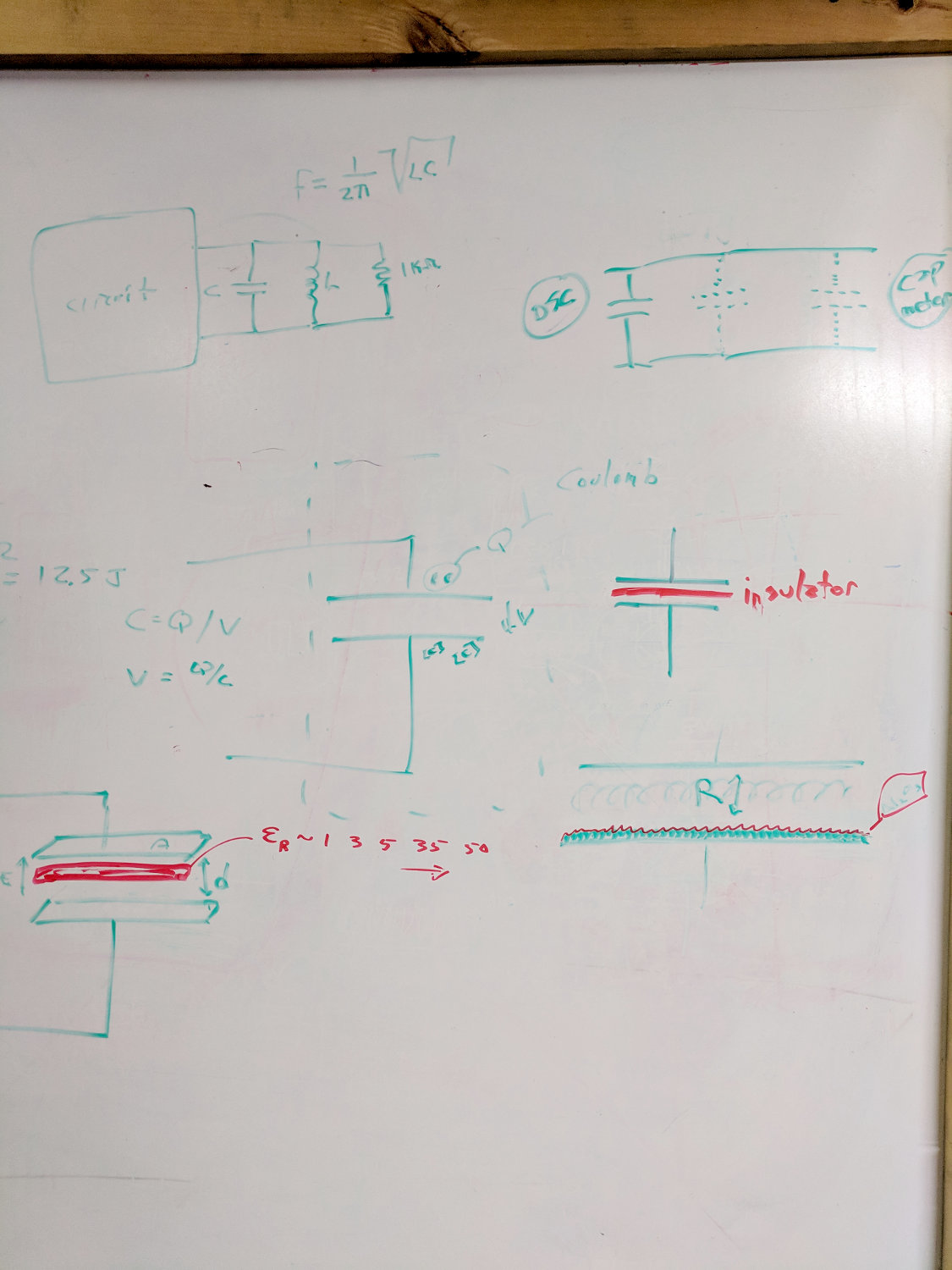
Some handwaving discussion of construction, electrolytic capacitor innards, and The Plague:
Session 6 – Whiteboard 1 – cap construction
A 1 F cap charged through a 1.8 kΩ resistor during most of the session to show what an 1800 s time constant looked like. Nope, it never quite got to the 3.5 V from the power supply, even when we all decided it was time to shut down!
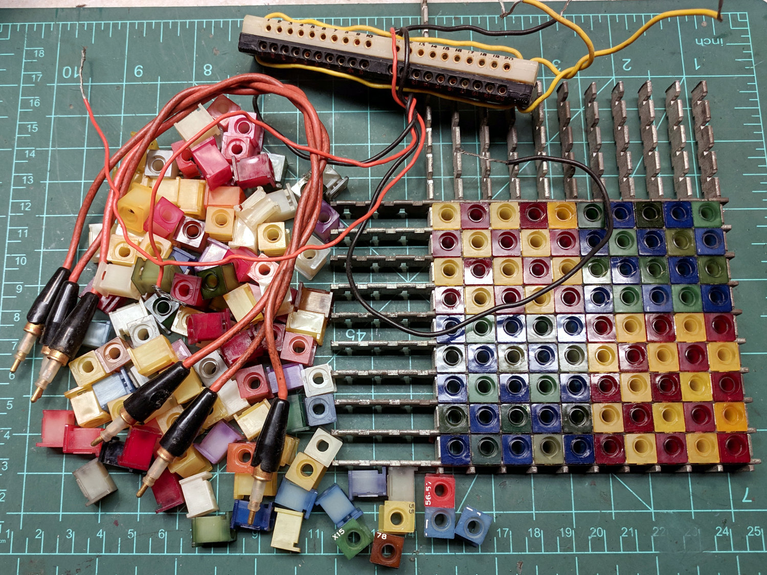
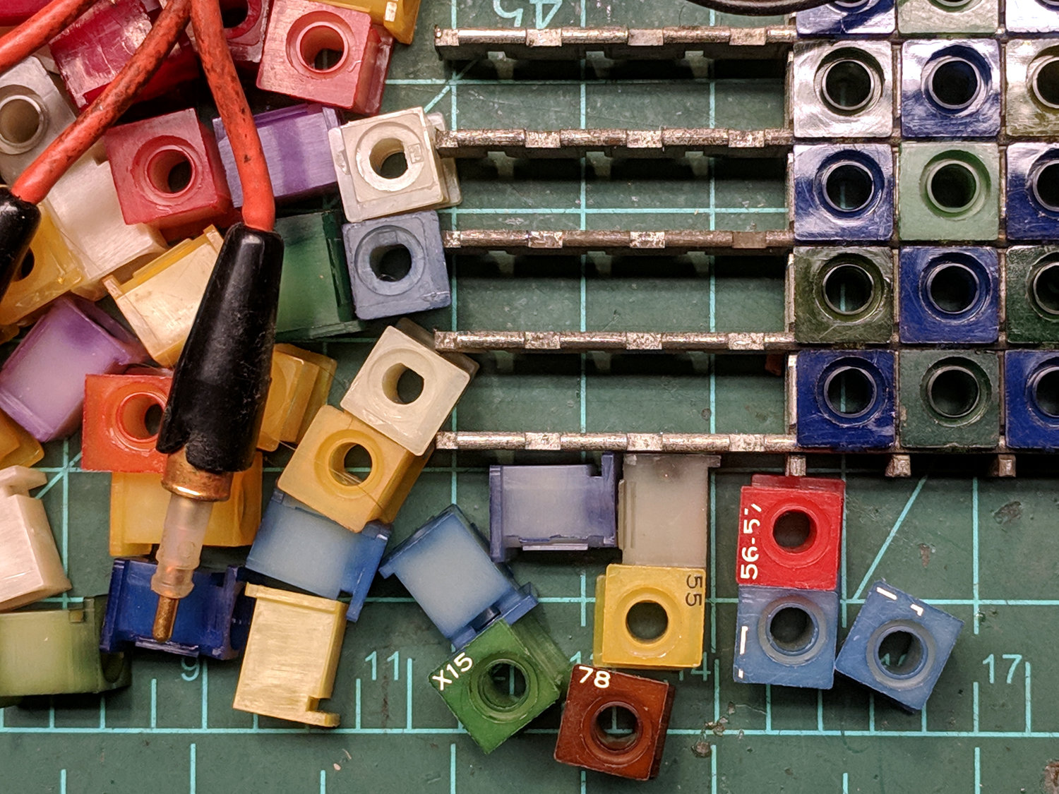
Around 1960, somebody my father knew at the Harrisburg AMP factory gave me a chunk of plugboard bandsawed from a scrapped computer or industrial controller, because he knew I’d enjoy it:
AMP Plug Board
He was right.
I spent months rearranging those little cubes (some with cryptic legends!) into meaningful (to me) patterns, plugging cables between vital spots, and imagining how the whole thing worked:
AMP Plug Board – detail
Long springs ran through the notches under the top of the blocks to connect the plug shells to circuit ground. The ends of the steel rails (still!) have raw bandsaw cuts, some of the blocks were sliced in two, the tip contact array behind the panel wasn’t included, and none of that mattered in the least.
Only a fraction of the original treasure trove survives. It was absolutely my favorite “toy” ever.
Quite some years ago, our Larval Engineer assembled the pattern you see; the hardware still had some attraction.
I’ve asked Mary to toss it in the hole with whatever’s left of me, when that day arrives …
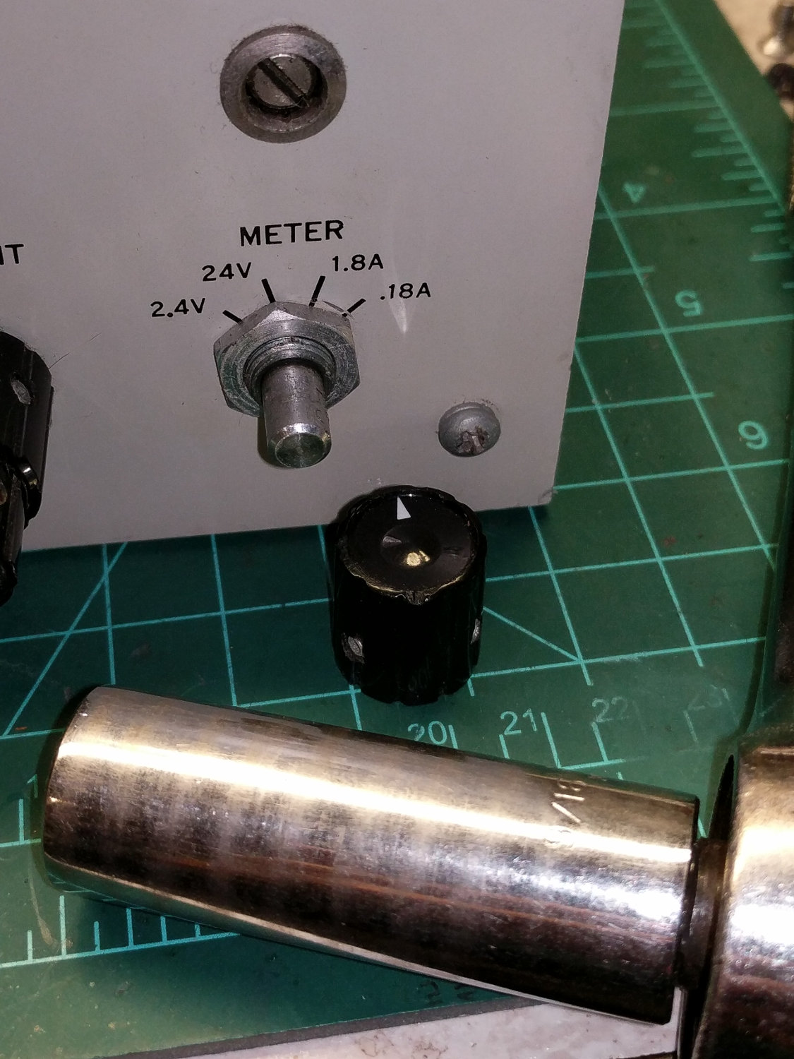
The meter range switch on Squidwrench’s HP 6201B bench power supply became erratic enough to get me to tear it apart:
HP 6201B Power Supply – meter switch nut
For future reference, apply a 9/16 inch deep socket after loosening two teeny setscrews in the knob.
The date codes suggest a mid-70s assembly, but the design dates back to the 60s with no plug-in anything:
HP 6201B Power Supply – meter switch in panel
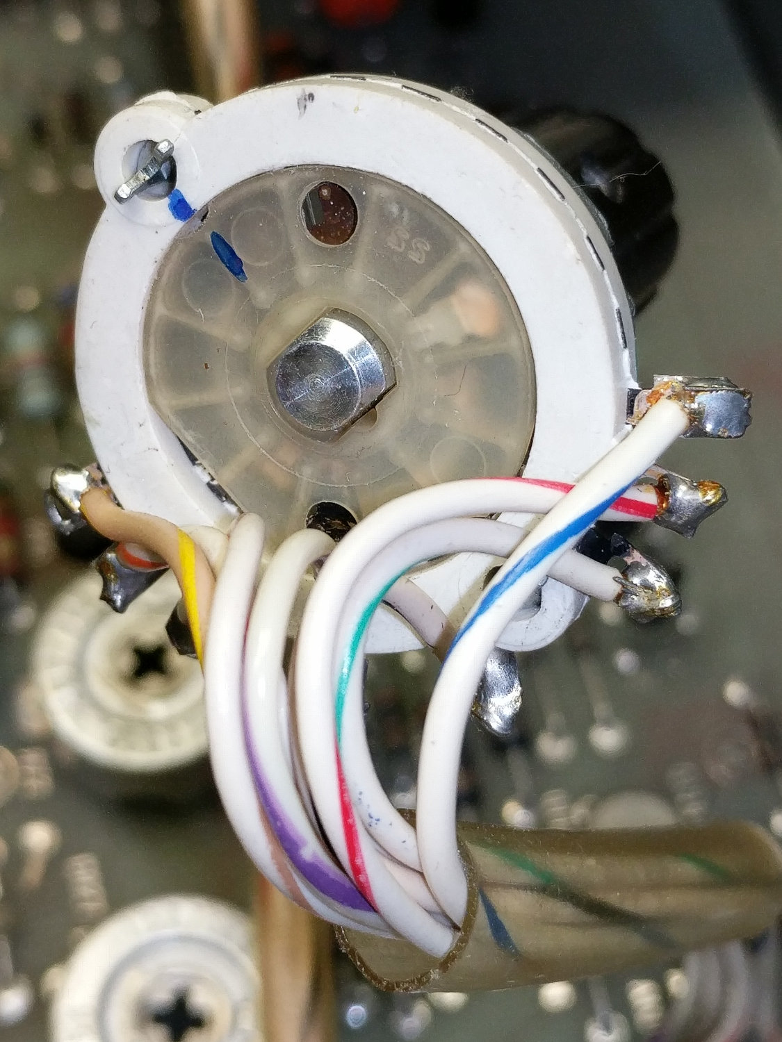
Rather than unsolder eight switch leads, I wrangled it into a visible location:
HP 6201B Power Supply – meter switch rear
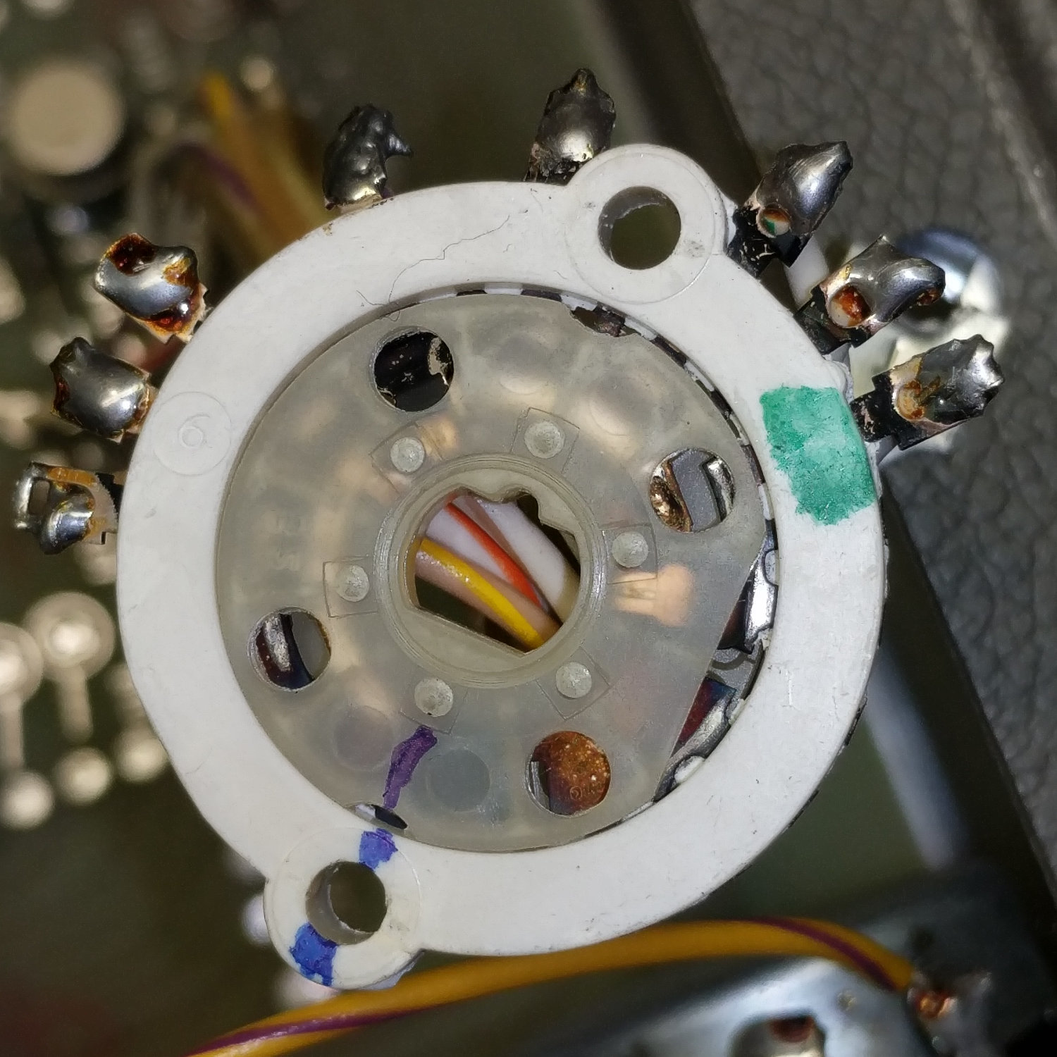
The knob and shaft sit on a separate metal bracket held in the white plastic ring with a pair of expanded prongs. Squashing the prongs together released the bracket, so I could see both sides of the switch wafer:
HP 6201B Power Supply – meter switch front
Note the copious markings which would, in the event of an actual finger fumble, give me a better chance of reassembling the spilled guts. Turned out not to be necessary, but it’s good to be prepared!
The actual repair consisted of easing a drop of DeoxIT Red into each side, spinning the central switch wafer / contacts a few dozen times, then reassembling in reverse order. Re-bending the prongs turned out to be the most difficult part, eventually requiring the designated Prydriver, and ended well enough.
A quick test with a 100 Ω power resistor shows the supply was working fine and the switch produced the expected results without glitches or twitches:
HP 6201B Power Supply – test load
You just can’t beat the performance of old lab equipment!
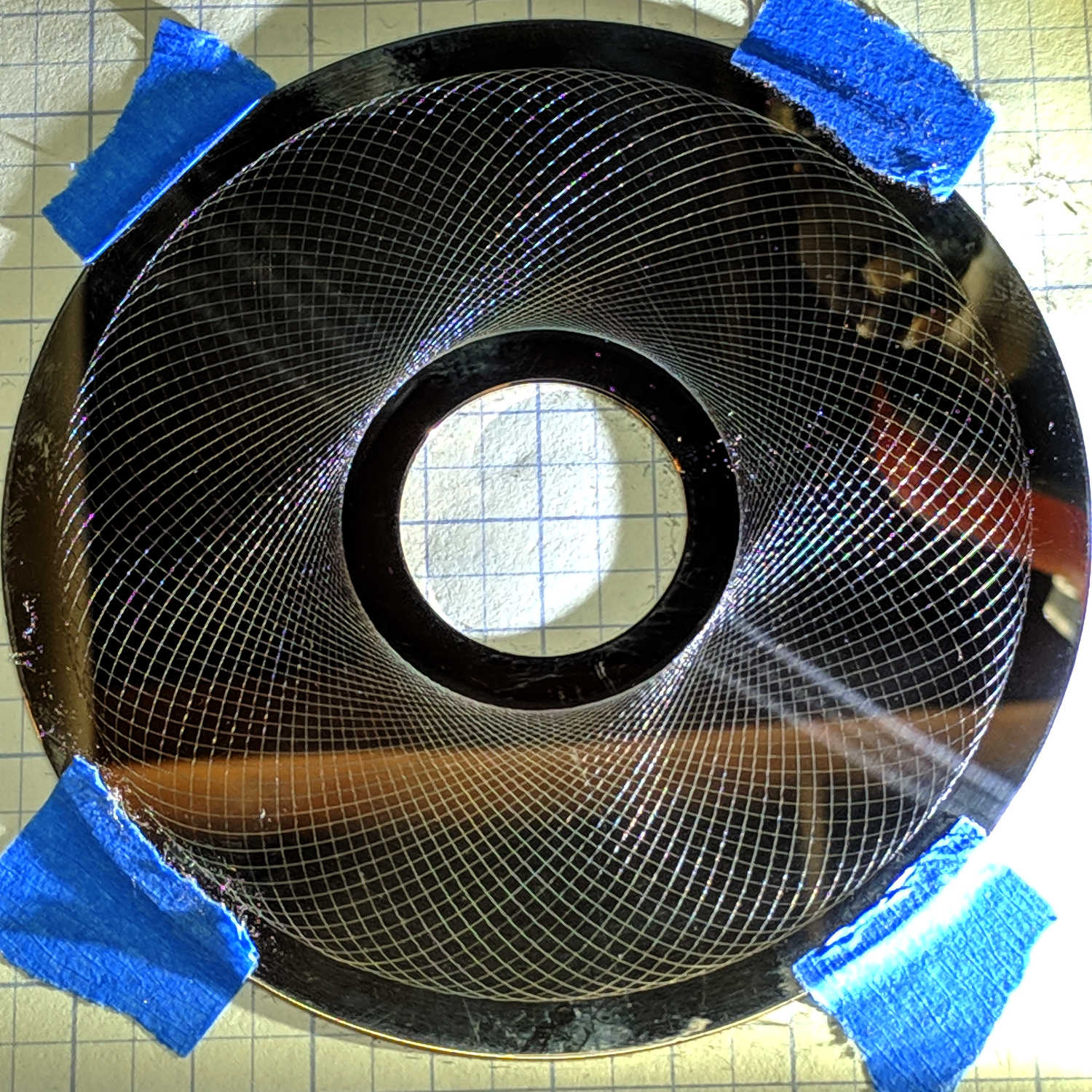
That’s with a 0.1 mm cut depth, sidelit with an LED flashlight.
Feeding those nine digits into the Guilloché pattern generator script should get you the same pattern; set the paper size to 109 mm and use Pen=0 to suppress the legend.
The same pattern at 0.3 mm cut depth looks about the same:
MPCNC – Guilloche 835242896 – HD plattter – 0.3mm
It’s slightly more prominent in real life, but not by enough to make a big difference. I should try a graduated series of tests, of course, which will require harvesting a few more platters from dead drives.
Either side will look great under a 21HB5A tube, although the disks are fingerprint and dust magnets beyond compare.
An obsolete Intuit / Roam Data credit card reader emerged from the heap:
Intuit Roam Data Reader
“Turn up the volume” suggested where the power comes from:
Intuit Roam Data Reader – plug wiring
They drive a LOUD, probably square-ish, audio signal through both “earphone”channels, rectify and regulate the output, and have plenty of power for the reader. The card data returns through the “mic” as another audio signal; I assume they choose an encoding well-suited for a dab of DSP decoding.
Nowadays, of course, 3.5 mm jacks are obsolete, audio data travels by Bluetooth, and you must keep a myriad batteries charged at all times.
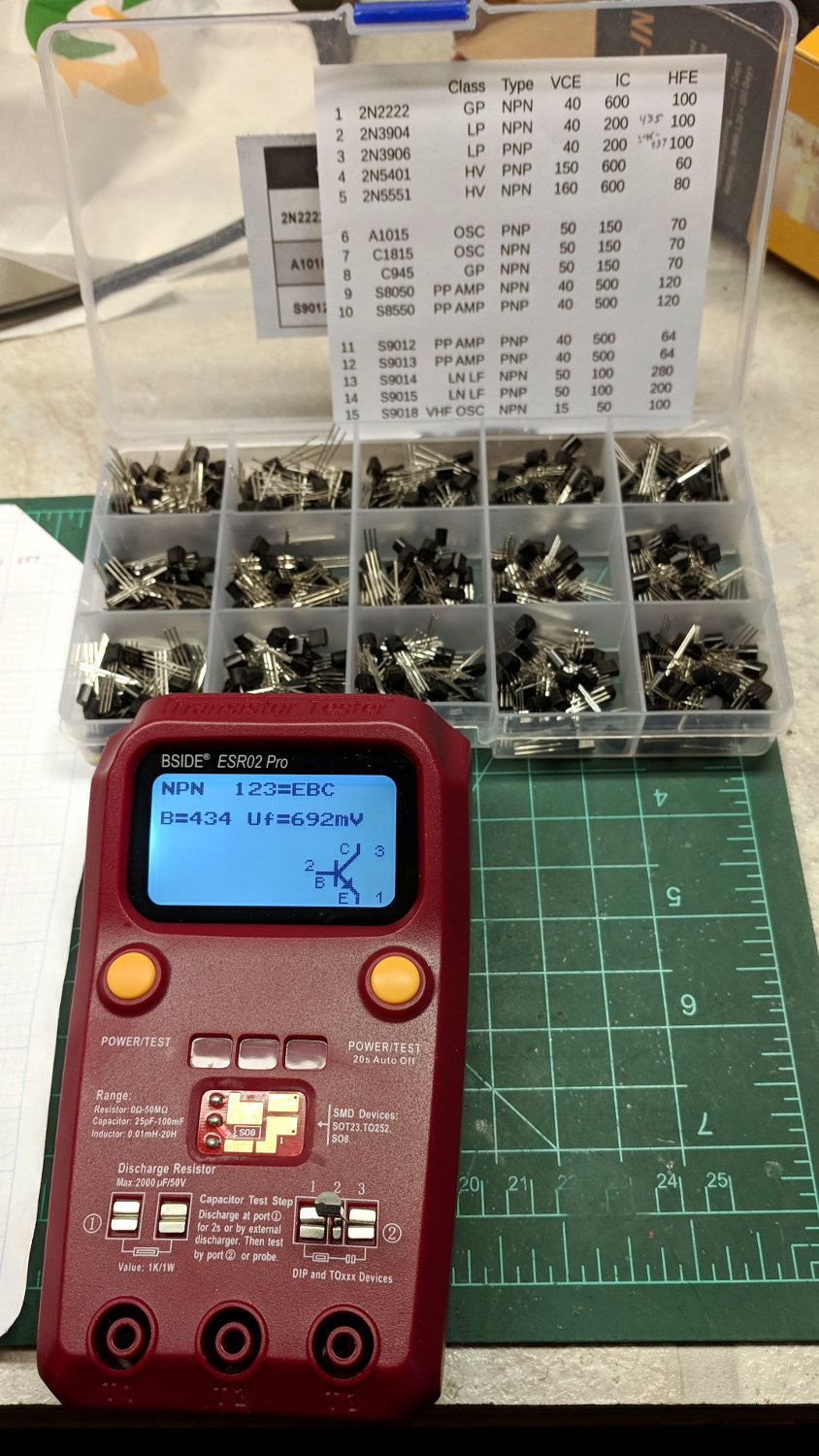
Most of the VBE variation comes from temperature differences: re-measuring the 2N3904 transistors with VBE ≅ 672 mV put them with their compadres at 677 mV.
The 2N3906 transistors have wider gain and VBE variations, so selecting a matched pair for the LM3909 current mirror makes sense.
The sheet inside the lid collects some essential parameters for ease of reference: