The Smell of Molten Projects in the Morning

Ed Nisley's Blog: Shop notes, electronics, firmware, machinery, 3D printing, laser cuttery, and curiosities. Contents: 100% human thinking, 0% AI slop.

Category: Electronics Workbench

Electrical & Electronic gadgets

  • CNC 3018-Pro: Probe Camera Case for Anonymous USB Camera

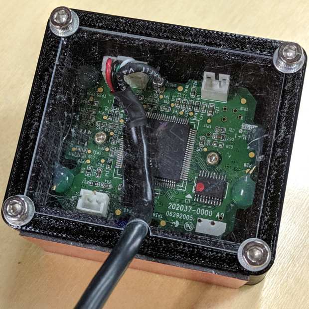
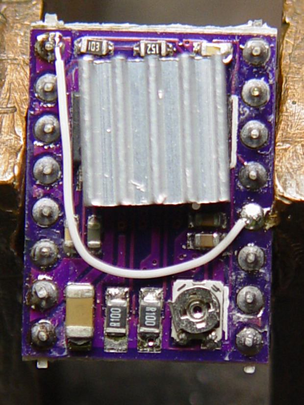
    The anonymous USB camera I used with the stereo zoom microscope not only works with VLC, but also with bCNC, and it has a round PCB with ears:

    CNC 3018-Pro - Probe Camera - PCB
    CNC 3018-Pro – Probe Camera – PCB

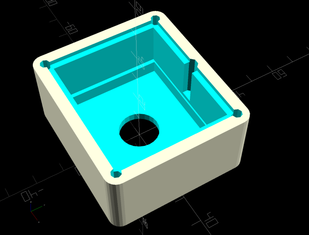
    Which suggested putting it in a ball mount for E-Z aiming:

    CNC 3018-Pro - Probe Camera - ball mount
    CNC 3018-Pro – Probe Camera – ball mount

    Black filament snippets serve as alignment pins to hold the ball halves together while they’re getting clamped. They’re epoxied into the upper half of the ball, because who knows when I’ll need to harvest the camera.

    The clamp mount descends from the Tour Easy Daytime Running Lights, with more screws and less fancy shaping:

    USB Camera - Round PCB Mount - solid model - build
    USB Camera – Round PCB Mount – solid model – build

    The clamp pieces fit around the ball with four M3 screws providing the clamping force:

    USB Camera - Round PCB Mount - solid model sectioned
    USB Camera – Round PCB Mount – solid model sectioned

    The whole affair sticks onto the Z axis carrier with double-sided foam tape:

    CNC 3018-Pro - Probe Camera - alignment
    CNC 3018-Pro – Probe Camera – alignment

    It barely clears the strut on the -X side of the carriage, although it does stick out over the edge of the chassis.

    After the fact, I tucked a closed-cell foam ring between the lens threads and the ball housing to stabilize the lens; the original camera glued the thing in place, but some fiddly alignment & focusing lies ahead:

    Alignment mirror - collimation
    Alignment mirror – collimation

    It’s worth noting that the optical axis of these cheap cameras rarely coincides with the physical central axis of the lens. This one requires a jaunty tilt, although it’s not noticeable in any of the pictures I tried to take.

    All in all, this one works just like the probe camera on the MPCNC.

    The OpenSCAD source code as a GitHub Gist:

    // CNC 3018-Pro Probe Camera mount for anonymous USB camera
    // Ed Nisley KE4ZNU – August 2019
    Layout = "Show"; // [Show, Build, Ball, Clamp, Bracket, Mount]
    //——-
    //- Extrusion parameters must match reality!
    // Print with 2 shells
    /* [Hidden] */
    ThreadThick = 0.25;
    ThreadWidth = 0.40;
    HoleWindage = 0.2;
    Protrusion = 0.1; // make holes end cleanly
    function IntegerMultiple(Size,Unit) = Unit * ceil(Size / Unit);
    inch = 25.4;
    ID = 0;
    OD = 1;
    LENGTH = 2;
    //——-
    // Dimensions
    //– Camera
    PCBThick = 1.2;
    PCBDia = 25.0;
    KeySize = [28.0,8.5,IntegerMultiple(PCBThick,ThreadThick)];
    KeyOffset = [0.0,2.0,0.0];
    KeyRadius = IntegerMultiple(sqrt(pow(KeySize.y – KeyOffset.y,2) + pow(KeySize.x/2,2)),0.01);
    echo(str("Key radius: ",KeyRadius));
    Lens = [14.0,18.0,25.0];
    BallID = PCBDia;
    BallOD = IntegerMultiple(2*KeyRadius,5.0);
    echo(str("Ball OD: ",BallOD));
    WallThick = 3.0;
    CableOD = 3.75;
    NumPins = 3;
    Pin = [1.75,1.8,5.0];
    Screw = [
    3.0,6.8,25.0 // M3 ID=thread, OD=washer, LENGTH=below head
    ];
    RoundRadius = IntegerMultiple(Screw[OD]/2,1.0); // corner rounding
    ClampSize = [BallOD + 2*WallThick,BallOD + 2*WallThick,20.0];
    echo(str("Clamp: ",ClampSize));
    MountSize = [5.0,BallOD,25.0];
    MountClearance = 1.0; // distance between clamp and mount
    Kerf = 2*ThreadThick;
    ScrewOC = [ClampSize.x – 2*RoundRadius,ClampSize.y – 2*RoundRadius];
    echo(str("Screw OC: ",ScrewOC));
    Insert = [ // brass insert: body, knurl,length
    3.9,4.9,8.0
    ];
    UseInsert = false;
    NumSides = 12*4;
    //——-
    module PolyCyl(Dia,Height,ForceSides=0) { // based on nophead's polyholes
    Sides = (ForceSides != 0) ? ForceSides : (ceil(Dia) + 2);
    FixDia = Dia / cos(180/Sides);
    cylinder(r=(FixDia + HoleWindage)/2,
    h=Height,
    $fn=Sides);
    }
    //——-
    // Components
    module CamBall(Section="Both") {
    Offset = (Section == "Both") ? 0 :
    (Section == "Upper") ? BallOD/2 :
    (Section == "Lower") ? -BallOD/2 :
    0;
    render(convexity=4)
    intersection(convexity = 3) {
    difference() {
    sphere(d=BallOD,$fn=NumSides);
    sphere(d=BallID,$fn=NumSides); // interior
    PolyCyl(CableOD,2*BallOD,8); // cable & lens holes
    translate([0,0,-Lens[LENGTH]])
    PolyCyl(Lens[OD],Lens[LENGTH],NumSides);
    translate([0,0,-PCBThick])
    PolyCyl(PCBDia,PCBThick,NumSides);
    translate(KeyOffset + [0,-KeySize.y/2,-PCBThick/2]) // PCB key
    cube(KeySize,center=true);
    for (i=[0:NumPins – 1])
    rotate(i*360/NumPins)
    translate([0,-(BallID + BallOD)/4,-Pin[LENGTH]/2])
    PolyCyl(Pin[OD],Pin[LENGTH],6);
    }
    translate([0,0,Offset])
    cube([BallOD,BallOD,BallOD] + 2*[Protrusion,Protrusion,0],center=true);
    }
    }
    module Clamp(Section="Both") {
    Offset = (Section == "Both") ? 0 :
    (Section == "Upper") ? ClampSize.z/2 :
    (Section == "Lower") ? -ClampSize.z/2 :
    0;
    render(convexity=4)
    intersection() {
    difference() {
    hull()
    for (i=[-1,1], j=[-1,1])
    translate([i*ScrewOC.x/2,j*ScrewOC.y/2,0])
    cylinder(r=RoundRadius,h=ClampSize.z,$fn=NumSides,center=true);
    sphere(d=BallOD + 2*HoleWindage,$fn=NumSides); // space around camera ball
    for (i=[-1,1], j=[-1,1]) // screws
    translate([i*ScrewOC.x/2,j*ScrewOC.y/2,-ClampSize.z])
    PolyCyl(Screw[ID],2*ClampSize.z,6);
    if (UseInsert)
    for (i=[-1,1], j=[-1,1]) // inserts
    translate([i*ScrewOC.x/2,j*ScrewOC.y/2,-(ClampSize.z/2 + Protrusion)])
    PolyCyl(Insert[OD],Insert[LENGTH] + Protrusion,8);
    cube([2*ClampSize.x,2*ClampSize.y,Kerf],center=true); // clamping gap
    }
    translate([0,0,Offset])
    cube([ClampSize.x,ClampSize.y,ClampSize.z] + 2*[Protrusion,Protrusion,0],center=true);
    }
    }
    module Bracket() {
    translate([ClampSize.x/2 + MountSize.x/2 + MountClearance,0,MountSize.z/2 – ClampSize.z/2])
    cube(MountSize,center=true);
    translate([ClampSize.x/2 + MountClearance/2,0,-(ClampSize.z + Kerf)/4])
    cube([MountClearance + 2*Protrusion,MountSize.y,(ClampSize.z – Kerf)/2],center=true);
    }
    module Mount() {
    union() {
    Clamp("Lower");
    Bracket();
    }
    }
    //——-
    // Build it!
    if (Layout == "Ball")
    CamBall();
    if (Layout == "Clamp")
    Clamp();
    if (Layout == "Bracket")
    Bracket();
    if (Layout == "Mount")
    Mount();
    if (Layout == "Show") {
    difference() {
    union() {
    color("Purple")
    Clamp("Upper");
    Mount();
    color("LimeGreen")
    CamBall();
    }
    rotate([0,0,45])
    translate([-ClampSize.x,0,0])
    cube(2*ClampSize,center=true);
    }
    }
    if (Layout == "Build") {
    Gap = 0.6;
    translate([-Gap*BallOD,Gap*BallOD,0])
    CamBall("Upper");
    translate([-Gap*BallOD,-Gap*BallOD,0])
    rotate([0,180,0])
    CamBall("Lower");
    translate([Gap*ClampSize.x,-Gap*ClampSize.y,ClampSize.z/2])
    rotate([0,180,0])
    Clamp("Upper");
    translate([Gap*ClampSize.x,Gap*ClampSize.y,ClampSize.z/2]) {
    rotate(180)
    Mount();
    }
    }

  • CNC 3018-Pro: Probe Camera Case for Logitch QuickCam Pro 5000

    The ball-shaped Logitch QuickCam Pro 5000 has a rectangular PCB, so conjuring a case wasn’t too challenging:

    Probe Camera Case - Logitech QuickCam Pro 5000 - bottom
    Probe Camera Case – Logitech QuickCam Pro 5000 – bottom

    That’s more-or-less matte black duct tape to cut down reflections.

    The top side has a cover made from scuffed acrylic scrap:

    Probe Camera Case - Logitech QuickCam Pro 5000 - top
    Probe Camera Case – Logitech QuickCam Pro 5000 – top

    The corners are slightly rounded to fit under the screw heads holding it in place.

    The solid model shows off the internal ledge positioning the PCB so the camera lens housing rests on the floor:

    3018 Probe Camera Mount - solid model
    3018 Probe Camera Mount – solid model

    The notch lets the cable out, while keeping it in one place and providing some strain relief.

    I though if a camera was recognized by V4L2 and worked with VLC, it was good to go:

    Logitech QuickCam Pro 5000 - short focus
    Logitech QuickCam Pro 5000 – short focus

    Regrettably, it turns out the camera has a pixel format incompatible with the Python opencv interface used by bCNC. This may have something to do with running the code on a Raspberry Pi, rather than an x86 box.

    The camera will surely come in handy for something else, especially with such a cute case.

    The OpenSCAD source code as a GitHub Gist:

    // Probe Camera Mount for CNC 3018-Pro Z Axis
    // Ed Nisley – KE4ZNU – 2019-08
    Layout = "Block"; // [Show,Build,Block]
    Support = false;
    /* [Hidden] */
    ThreadThick = 0.20;
    ThreadWidth = 0.40;
    HoleWindage = 0.2;
    Protrusion = 0.1; // make holes end cleanly
    function IntegerMultiple(Size,Unit) = Unit * ceil(Size / Unit);
    ID = 0;
    OD = 1;
    LENGTH = 2;
    inch = 25.4;
    //———————-
    // Dimensions
    PCB = [45.0,38.0,1.5]; // Logitech QuickCam Pro 5000 ball camera
    PCBLip = 1.0; // max non-component border
    PCBChamfer = 3.0; // cut along XY axes for corner bevel
    PCBClearTop = 15.0; // cables & connectors
    PCBClearSides = [0.5,0.5]; // irregular edges & comfort zone
    PCBClearBelow = 5.0; // lens support bracket rests on floor
    Lens = [11.5,14.2,3.0]; // LENGTH = beyond PCBClearBelow bracket
    LensOffset = [-1.5,0.0,0]; // distance from center of board
    CableOD = 4.5;
    BaseThick = Lens[LENGTH];
    Screw = [
    3.0,6.8,18.0 // M3 OD=washer, LENGTH=below head
    ];
    RoundRadius = IntegerMultiple(Screw[OD]/2,1.0); // corner rounding
    ScrewOC = [PCB.x + 2*sqrt(Screw[OD]),PCB.y + 2*sqrt(Screw[OD])];
    echo(str("Screw OC: ",ScrewOC));
    Lid = [ScrewOC.x,ScrewOC.y,1.0/16.0 * inch]; // top cover plate
    echo(str("Lid: ",Lid));
    BlockSize = [ScrewOC.x + 2*RoundRadius,ScrewOC.y + 2*RoundRadius,
    BaseThick + PCBClearBelow + PCB.z + PCBClearTop + Lid.z];
    echo(str("Block: ",BlockSize));
    NumSides = 2*3*4;
    //———————-
    // Useful routines
    module PolyCyl(Dia,Height,ForceSides=0) { // based on nophead's polyholes
    Sides = (ForceSides != 0) ? ForceSides : (ceil(Dia) + 2);
    FixDia = Dia / cos(180/Sides);
    cylinder(r=(FixDia + HoleWindage)/2,
    h=Height,
    $fn=Sides);
    }
    // Basic shapes
    // Overall block
    module Block() {
    difference() {
    hull()
    for (i=[-1,1], j=[-1,1])
    translate([i*ScrewOC.x/2,j*ScrewOC.y/2,0])
    cylinder(r=RoundRadius,h=BlockSize.z,$fn=NumSides);
    for (i=[-1,1], j=[-1,1]) // corner screws
    translate([i*ScrewOC.x/2,j*ScrewOC.y/2,BlockSize.z – Screw[LENGTH]])
    cylinder(d=Screw[ID],h=2*Screw[LENGTH],$fn=8); // cylinder = undersized
    translate(LensOffset + [0,0,-Protrusion]) // lens body
    PolyCyl(Lens[OD],2*BlockSize.z,NumSides);
    translate([0,0,BlockSize.z/2 + BaseThick]) // PCB lip on bottom
    cube([PCB.x – 2*PCBLip,PCB.y,BlockSize.z],center=true);
    translate([0,0,BlockSize.z/2 + BaseThick + PCBClearBelow]) // PCB clearance
    cube([PCB.x + 2*PCBClearSides.x,PCB.y + 2*PCBClearSides.y,BlockSize.z],center=true);
    translate([0,0,BlockSize.z – Lid.z/2]) // lid recess
    cube(Lid + [0,0,Protrusion],center=true);
    translate([0,Lid.y/2 – CableOD/2,BaseThick + PCBClearBelow + PCB.z]) // cable exit
    hull()
    for (j=[-1,1])
    translate([0,j*CableOD/4,0])
    rotate(180/8)
    PolyCyl(CableOD,BlockSize.z,8);
    }
    }
    //- Build it
    if (Layout == "Block")
    Block();
    if (Layout == "Show") {
    Block();
    }
    if (Layout == "Build") {
    Block();
    }

  • CNC 3018-Pro: DRV8825 Hack for 1:8 Microstep Mode

    The CAMTool V3.3 board on the CNC 3018-Pro hardwires the three DRV8825 stepper driver chips in 1:32 microstep mode by pulling all three Mode pins high. Unlike most CNC boards, it does not include jumpers to let you select different microstep modes; the designers know you want as many microsteps as you can possibly get.

    As it turns out, 1:32 microstep mode requires 1600 steps for each millimeter of travel and, because GRBL tops out around 30 k step/s, the maximum speed is about 18.75 mm/s = 1125 mm/min. Which isn’t at bad, but, because I intend to use the thing for engraving, rather than the light-duty machining it’s (allegedly) capable of performing, running at somewhat higher speeds will be desirable.

    For sure, a 3018-Pro does not have a physical resolution of 625 nm.

    If you’re willing to settle for a mere 400 step/mm = 2.6 µm, then you can just ground the Mode 2 pin to get 1:8 microstep mode:

    DRV8825 - Stepper Motor Controller - Microstep Modes
    DRV8825 – Stepper Motor Controller – Microstep Modes

    Rewiring the CAMTool board isn’t feasible, but hacking the DRV8825 carrier PCB doesn’t require much effort.

    So, we begin.

    Clamp the PCB in a vise, grab the Mode 2 pin with a needle-nose pliers, apply enough heat to melt the solder completely through the board, and yank that pin right out:

    CAMTool V3.3 - DRV8825 M2 pin removed
    CAMTool V3.3 – DRV8825 M2 pin removed

    I do wonder how the layout folks managed to reverse the “N” for the Enable pin. Perhaps it’s a Cyrillic И in a dead-simple font?

    With that done, add a snippet of wire from M2 to the GND pin in the opposite corner to complete the job:

    CAMTool V3.3 - DRV8825 wired for 8 ustep mode
    CAMTool V3.3 – DRV8825 wired for 8 ustep mode

    Despite that picture, remember to plug the DRV8825 boards into the CAMTool V3.3 board with the heatsink downward and the twiddlepot on the top, as shown in the little instruction book you got with the hardware:

    SainSmart Genmitsu CNC Router 3018PRO-User Manual - DRV8825 orientation
    SainSmart Genmitsu CNC Router 3018PRO-User Manual – DRV8825 orientation

    Recompute the step/mm value in 1:8 microstep mode:

    400 step/mm = (200 full step/rev) × (8 microstep/full step) / (4 mm/rev)

    Then set the corresponding GRBL parameters:

    $100=400
    $101=400
    $102=400

    The 3018-Pro should work exactly like it did before, maybe a little noisier if your ears are up to the task.

    Moah Speed comes later …

  • CNC 3018-Pro: CAMTool V3.3 USB Power Diode

    The CAMTool V3.3 board dispenses with fancy USB power switching circuitry:

    CAMTOOL CNC-V3.3 schematic - USB Power Entry
    CAMTOOL CNC-V3.3 schematic – USB Power Entry

    The NUP2201 is an ESD clamp diode / suppressor IC, which is a nice touch, but FU1, a simple 300 mA polyfuse, is the only thing standing between the USB cable and the on-board +5 V regulator. In real life, it looks like this:

    CAMTool V3.3 - USB power fuse
    CAMTool V3.3 – USB power fuse

    It’s the little black rectangle between the USB jack and the CH340 USB-to-serial chip. The

    The far end of the USB cable plugs into a Raspberry Pi, a device known for unseemly fussiness about USB power, so I unsoldered the fuse and installed a diode:

    CAMTool V3.3 - USB power diode
    CAMTool V3.3 – USB power diode

    It’s a BAT54 Schottky diode, pointed toward the right to prevent current from the board getting to the Pi. Pin 2 (toward the bottom) isn’t connected to anything inside the package, either, so it’s all good.

    I suppose if one were a stickler for detail, one could gimmick the diode in series with the fuse, but I figured that’s a solution for a problem well down on the probability list …

  • DRV8825 Stepper Driver: Fast vs. Mixed Decay Current Waveforms

    Herewith, a look at CNC 3018-Pro stepper motor current waveforms as a function of supply voltage, PWM decay mode, and motor speed.

    The scope displays X and Y axis motor current at 1 A/div, with sensing through a pair of Tektronix Hall effect current probes:

    CNC 3018-Pro - XY axes - Tek current probes
    CNC 3018-Pro – XY axes – Tek current probes

    The X axis driver is an unmodified DRV8825 PCB operating in default mixed-decay mode. The Y axis DRV8825 has its DECAY pin pulled high, thereby putting it in fast decay mode.

    The scope timebase varies to match the programmed feed rate. Because the X and Y axes move simultaneously, each axis moves at 1/√2 the programmed speed:

    G1 X10 Y10 F100 → 71 mm/min on X and Y

    The motor generates minimal back EMF at slow speeds, so the winding sees nearly the full supply voltage. As described in the previous post, the basic problem arises when the current rises too fast during each PWM cycle:

    V = L di/dt
    di/dt = 24 V / 3 mH = 8 kA/s

    The first 1:32 microstep away from 0 calls for 5% of max current = 50 mA at a 1 A peak. The DRV8825 datasheet says the PWM typically runs at 30 kHz = 33 µs/cycle, during which the current will change by 270 mA:

    267 mA = 8 kA/s × 33.3 µs

    Notice how the current slams to a nearly constant, much-too-high value just after the first microstep. The incorrect current level decreases with lower supply voltage, because the rate-of-change decreases and the commanded current level reaches the actual (incorrect) current sooner.

    Varying the motor voltage at a constant 10 mm/min:

    3018 XY - Mixed Fast - 24V - 10mm-min 1A-div
    3018 XY – Mixed Fast – 24V – 10mm-min 1A-div
    3018 XY - Mixed Fast - 20V - 10mm-min 1A-div
    3018 XY – Mixed Fast – 20V – 10mm-min 1A-div
    3018 XY - Mixed Fast - 15V - 10mm-min 1A-div
    3018 XY – Mixed Fast – 15V – 10mm-min 1A-div
    3018 XY - Mixed Fast - 12V - 10mm-min 1A-div
    3018 XY – Mixed Fast – 12V – 10mm-min 1A-div
    3018 XY - Mixed Fast - 10V - 10mm-min 1A-div
    3018 XY – Mixed Fast – 10V – 10mm-min 1A-div

    Note that reducing the supply voltage doesn’t change the motor winding current, because the DRV8825 controls the current during each microstep, at least to the best of its ability.

    Also note that the current overshoots the target for those microsteps, even when the motor is stopped, because there’s no back EMF, so the power dissipation is too high even at rest.

    Enough back EMF appears at 100 mm/min to begin tamping down the current overshoot at 24 V:

    3018 XY - Mixed Fast - 24V - 100mm-min 1A-div
    3018 XY – Mixed Fast – 24V – 100mm-min 1A-div

    The current waveform looks good at 12 V:

    3018 XY - Mixed Fast - 12V - 100mm-min 1A-div
    3018 XY – Mixed Fast – 12V – 100mm-min 1A-div

    The back EMF at 1000 mm/min nearly eliminates the overshoot at 24 V, with fast decay in the Y axis causing some PWM ripple:

    3018 XY - Mixed Fast - 24V - 1000mm-min 1A-div
    3018 XY – Mixed Fast – 24V – 1000mm-min 1A-div

    Both decay modes look good at 12 V:

    3018 XY - Mixed Fast - 12V - 1000mm-min 1A-div
    3018 XY – Mixed Fast – 12V – 1000mm-min 1A-div

    At 1500 mm/min, the highest reasonable speed for the thing, and a 24 V supply, both waveforms still look good:

    3018 XY - Mixed Fast - 24V - 1500mm-min 1A-div
    3018 XY – Mixed Fast – 24V – 1500mm-min 1A-div

    However, the back EMF is now high enough to buck the 12 V supply, preventing the current from decreasing fast enough in mixed decay mode (top trace):

    3018 XY - Mixed Fast - 12V - 1500mm-min 1A-div
    3018 XY – Mixed Fast – 12V – 1500mm-min 1A-div

    Tweaking the GRBL config to allow 2000 mm/min feeds shows the waveforms starting to become triangular, even at 24 V:

    3018 XY - Mixed Fast - 24V - 2000mm-min 1A-div
    3018 XY – Mixed Fast – 24V – 2000mm-min 1A-div

    And a 12 V supply opposed by the back EMF simply can’t change the current fast enough to keep up with the DRV8825 microstep current levels:

    3018 XY - Mixed Fast - 12V - 2000mm-min 1A-div
    3018 XY – Mixed Fast – 12V – 2000mm-min 1A-div

    Bottom line: a +12 V motor supply and DRV8825 drivers modified to run in fast decay mode look like the best setup for the 3018-Pro: good current control at low speeds with enough moxie to handle higher speeds.

    I should hack the DRV8825 boards into 1:8 microstep mode to reduce the IRQ rate by a factor of four, then see what happens to the back EMF at absurd speeds.

  • DRV8825 Stepper Driver: Forcing Fast Decay Mode in a (Likely) Counterfeit Chip

    The DRV8825 stepper driver chip defaults to mixed decay mode, which TI defines thusly:

    Mixed decay mode begins as fast decay, but at a fixed period of time (75% of the PWM cycle) switches to slow decay mode for the remainder of the fixed PWM period. This occurs only if the current through the winding is decreasing (per the indexer step table); if the current is increasing, then slow decay is used.

    The 24 V supply on the CNC 3018-Pro provides too much voltage for the motors, because slow decay mode can’t handle those rising slopes:

    3018 XY - Mixed Fast - 24V - 10mm-min 12V 1A-div
    3018 XY – Mixed Fast – 24V – 10mm-min 12V 1A-div

    Note that “rising” means the current increases with either polarity from 0 A at the midline. The DRV8825 uses a MOSFET H-bridge to drive winding current in either direction from the +24 V motor supply voltage.

    Both traces show motor winding current at 1 A/div, with the XY axes creeping along at 10 mm/min (thus, 7.1 mm/min each). The upper trace is the X axis, with a stock DRV8825 module in mixed decay mode. The lower trace is the Y axis, with its DRV8825 hacked into fast decay mode.

    The basic problem, about which more later, comes from the current rising too fast during each PWM cycle:

    V = L di/dt
    di/dt = 24 V / 3 mH = 8 kA/s

    The first 1:32 microstep away from 0 calls for 5% of max current = 50 mA at a 1 A peak. The DRV8825 datasheet says the PWM typically runs at 30 kHz = 33 µs/cycle, during which the current will change by 270 mA:

    267 mA = 8 kA/s × 33.3 µs

    Some preliminary measurements suggest these (probably counterfeit) DRV8825 chips actually run at 16 kHz = 66 µs/cycle:

    3018 X - ripple 1 step - 18V - A0 B-90 500mA-div
    3018 X – ripple 1 step – 18V – A0 B-90 500mA-div

    During those cycles the current can increase by more than 500 mA. The first scope picture shows an abrupt increase to maybe 700 mA, so, yeah, that’s about right.

    Having the wrong current in one winding means the motor isn’t positioned correctly during those microsteps. The 3018-Pro runs at (an absurd) 1600 µstep/mm, so being off by even a full step isn’t big deal in terms of positioning.

    The real problem comes from running nearly 1 A through both windings. Those little motors run really hot: they’re dissipating twice what they should be.

    Anyhow, the pin layout shows the DRV8825 DECAY mode selection on pin 19:

    DRV8825 pinout
    DRV8825 pinout

    Which sits on an inconveniently skinny little PCB pad, fifth from the left on the bottom:

    DRV8825 PCB - open Decay pin
    DRV8825 PCB – open Decay pin

    Memo to Self: Don’t make that mistake when you lay out a PCB. Always put a little pad or via on a disconnected pin, so as to have a hand-soldering target big enough to work with.

    The objective is to pull the pin high:

    DRV8825 DECAY pin settings
    DRV8825 DECAY pin settings

    Pin 15, in the lower left corner, provides the output of a 3.3 V linear regulator, with its PCB trace connected to the left side of the ceramic cap:

    DRV8825 PCB - Decay pin wired low
    DRV8825 PCB – Decay pin wired low

    On the scale of TSSOP packages, even 30 AWG Wire-Wrap wire looks like a bus bar!

    Those are two different PCBs. The crappy TI logos, not easily visible in those low-res pix, on both ICs suggest they’re by-now-typical counterfeits, so seeing a factor-of-two difference in PWM frequency isn’t surprising.

  • Raspberry Pi vs. MicroSD: Another One Bites the Dust

    The Raspberry Pi running the MPCNC recently seized up with baffling symptoms, which generally indicates the poor little MicroSD card serving as a “hard disk” has failed:

    Defunct Sandisk Ultra 32 GB MicroSD
    Defunct Sandisk Ultra 32 GB MicroSD

    I managed to open a terminal emulator, whereupon all of the non-built-in shell commands couldn’t be found.

    Proceed as before: binary-copy the entire MicroSD card to another one, pop it in the RPi, and it’s all good again.

    For the record, the new card is an unused Samsung Evo Plus. I do not understand the difference between the “Evo Plus” and “Evo+” branding, other than to suspect one of being a very good fake.

    In round numbers, MicroSD cards seem to last a year under what seems like not-too-demanding service; I’m not running the MPCNC all day, every day.