Ed Nisley's Blog: Shop notes, electronics, firmware, machinery, 3D printing, laser cuttery, and curiosities. Contents: 100% human thinking, 0% AI slop.
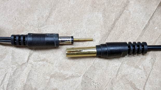
A Dell soundbar under the landscape monitor suffices for my simple audio needs, and, when the Dell U2711 went toes-up, I conjured a 12 V wart from the heap. A recent cleanup made a smaller wart available, but required mating two coaxial plugs:
Coax power plugs – brass tube connector
A snippet of brass tube suffices for the center pin. The outer shell is a larger brass tube, slit lengthwise, trimmed to fit the plug circumference and rolled around a smaller drill bit to make it springy in the right direction.
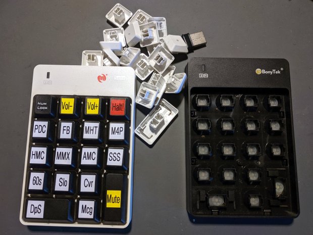
I swapped the Frankenpad + receiver to the least-conspicuous streamer and, someday, I’ll update all the labels on all the keypads to match the current streams. Until then, the white keycaps shall remain in the same bag as the defunct black keypad, tucked into the Big Box o’ USB mice & suchlike.
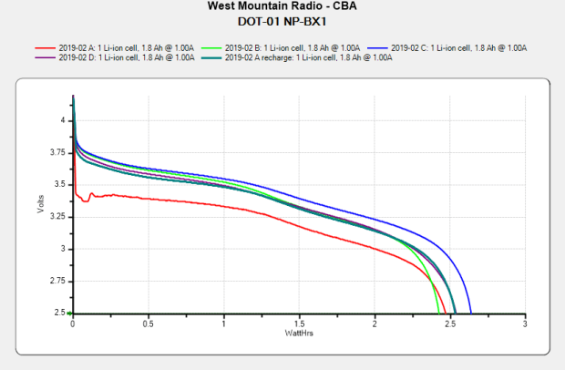
After eight months of regular use, they’re even further into mediocre:
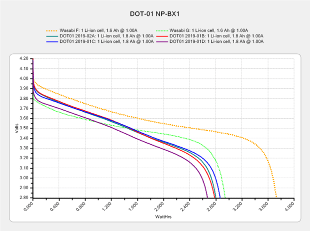
Sony DOT-01 NP-BX1 – 2019-10-29
In round numbers, they’re down from 2.8 W·h to 2.5 W·h and now run the camera for about 70 minutes, rather than 90+ when new. Our typical rides go for about an hour, which means I must swap batteries somewhere along the way.
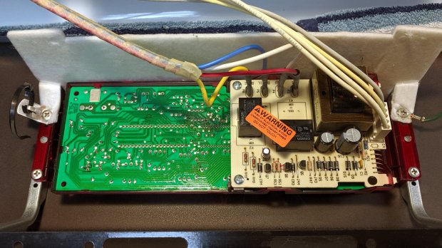
For the last year or so, the oven temperature control on our Kenmore gas stove has been decreasingly stable, sometimes varying by 100 °F from the setpoint before settling down somewhere close to what it should be. Spotting a replacement control board for a bit over $100, I decided the board used an absolute rotary encoder of the open-frame variety, so I took the thing apart:
Kenmore oven control – PCB overview
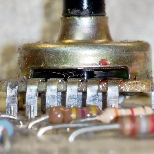
The encoder was, indeed, an open frame:
Kenmore oven control – rotary encoder
The red droplet is DeoxIT, the rest of which went inside, just ahead of the contact fingers, and got vigorously massaged across the switch contacts on the wafer by spinning the shaft.
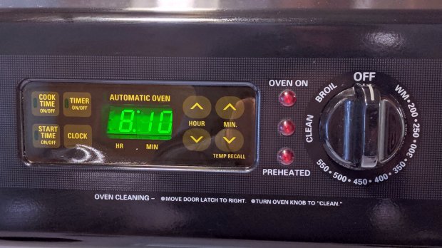
Some time ago, the membrane over the TIMER ON/OFF switch cracked and I applied a small square of Kapton tape. Having the entire controller in hand, I replaced the square with a strip of 2 inch Kapton, carefully aligned with the bezel marks embossed on the membrane, and now it’s smooth all over:
Kenmore oven control – Kapton tape cover
The MIN(ute) ^ switch required a much firmer than usual push, so I tucked a shim cut from a polypropylene clamshell between the membrane and the pin actuating the switch.
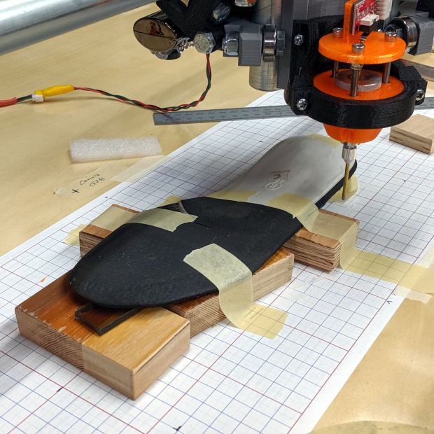
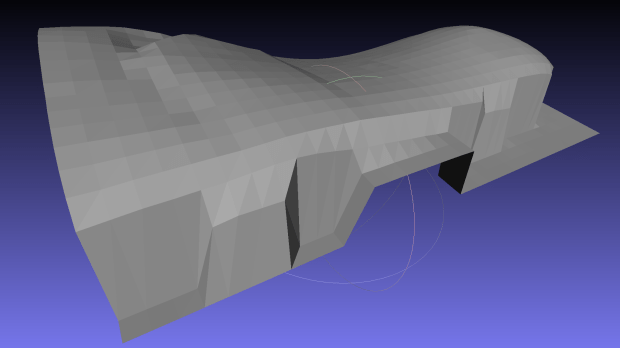
I set up an orthotic shoe insert on the MPCNC and unleashed the Z-Axis height probe on it:
Orthotic – bottom probing
In principle, the grid keeps the object aligned with the machine axes and the blocks put the upper surface more-or-less parallel with the platform. The XY origin, at the G28 location I’ve been using for tool changes, is on the midline of the sole, with Z touched off by probing the platform beside the sole.
The only interesting part of the orthotic is the rigid white plastic plate, which extends about 20 mm into a pocket in the black foam, so the probe area excludes the bendy part.
I’m abusing the bCNC Auto-level probe routine to get the height map, because it produces a tidy file of XYZ coordinates with three header lines describing the overall probe area:
The first two lines give the X and Y coordinate ranges and number of samples. The third line is the Z axis range and probe speed (?). After that, it’s just probed XYZ coordinates, all the way down.
Meshlab can import ASC files consisting of XYZ coordinates, with the ability to skip a specific number of header lines:
Meshlab ASC file import – header lines
If you don’t skip those three lines, then you get three additional points, far off in XYZ space, that will confuse the next step.
Checking the Grid Triangulation box (the default) produces a nicely lofted sheet:
Orthotic – R bottom triangulated
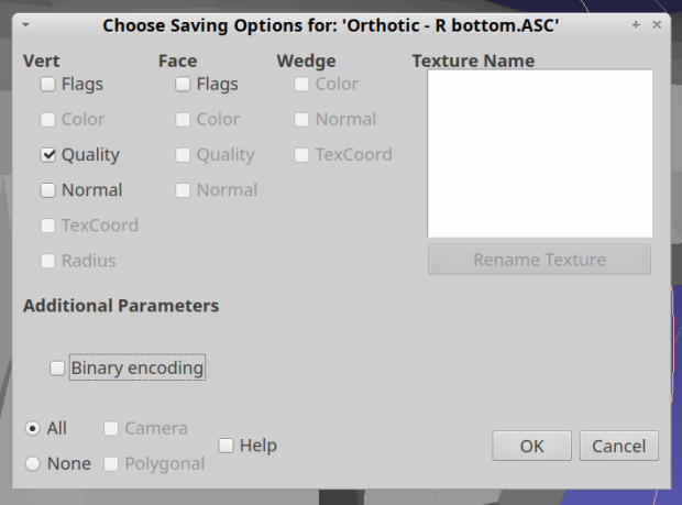
It is, however, a single-sided sheet, not a manifold 3D object. After a few days of screwing around, I’m unable to find any (automatic, reliable, non-manual) way to solidify the thing in Meshlab, so just save it as a PLY file in ASCII format:
Import it into Meshmixer, Ctrl-A to select the whole thing, click (Select →) Edit → Extrude, pick Y-Axis and Flat EndType, then extrude a convenient base in the negative direction:
Meshmixer – Y-Axis extrusion
For whatever reason, some 3D programs show machine-tool coordinates with Z pointing upward and others aim the Z axis at your face. Both must have made sense at the time, because Meshmixer defaults to swapping the Y and Z coordinates on import / export.
The Density slider controls the number of generated faces in the extruded section, so tune for best results.
I have no idea what Harden does.
Accept the result and you have a solid object suitable for further modeling.
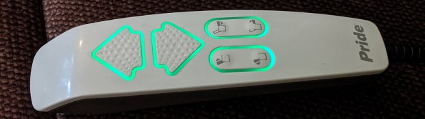
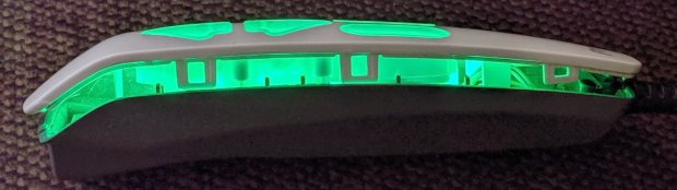
For reasons not relevant here, we recently decontaminated a second lift chair, this one in bariatric size (so it doesn’t suffer from fuzz-shaving struts) with a six-switch control pod:
Pride lift chair control – dimmed LEDs
The green LED-lit buttons were so bright I took it apart to see what could be done; the picture shows the considerably dimmed result.
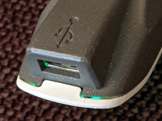
Start by prying outward on the tab at the USB charging port:
Pride lift chair control – USB port latch
Done right, you can then release the latches along the sides:
Pride lift chair control – side opened
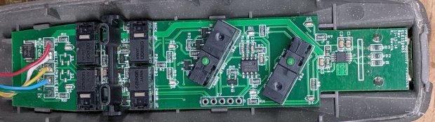
It’s impossible to photograph the PCB with the LEDs active, but here’s what it looks like without power:
Pride lift chair control – PCB overview
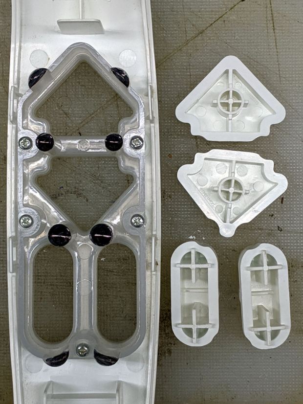
The eight (!) SMD LEDs align with light pipes around the switch openings:
Pride lift chair control – button keys
The black dots come from Sharpie ink daubed in the shallow recesses intended to nestle around the LEDs. Note that the four switch caps have unique keying, so you can’t put them back incorrectly without some effort.
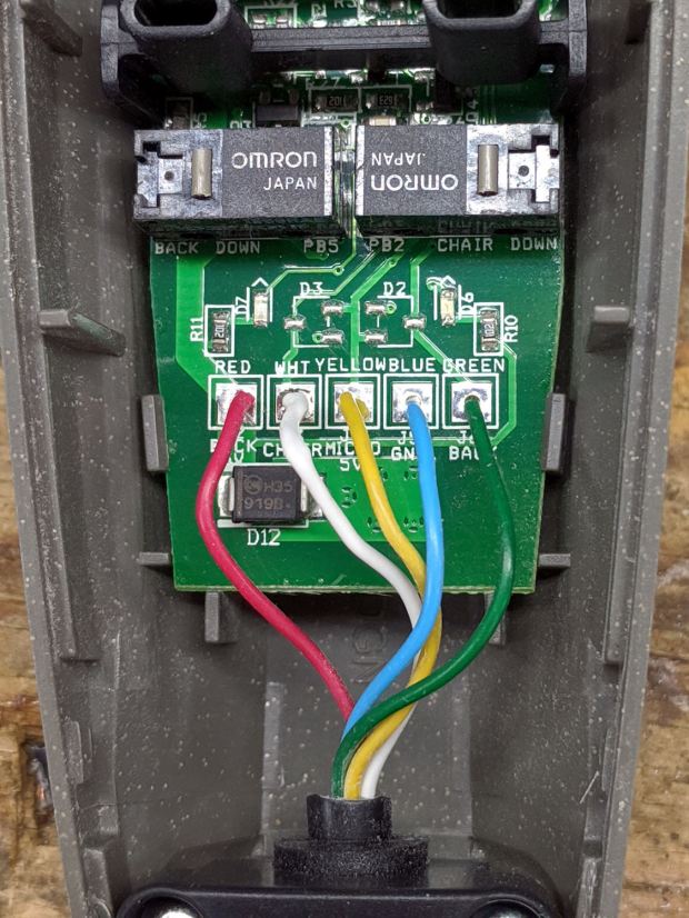
While we’re inside, here’s a closer look at the cable entry point, just in case I must replace the industrial-strength coily cord:
Pride lift chair control – cable entry
Unfortunately, it has a five-conductor cable, so a cheap phone coily cord (remember when phones had coily cords?) won’t suffice.
The PCB sports a pair of PICs, one of which seems to handle the buttons. I betcha the cable dates back to the days of hard-wired power switches, with the PIC now handling the intricate logic of deciding which motors to actuate for each function, then controlling MOSFETs as fake switch contacts.
The other PIC snuggles against the USB interface, which the manual describes as a charging-only port. It might also serve as a programming interface for the main PIC; admittedly the notion of a firmware upgrade for a lift chair seems far-fetched.
Reassembly is in reverse order with a resounding snap at the conclusion. It works fine and you (well, I) can now look at the control pod without sunglasses.
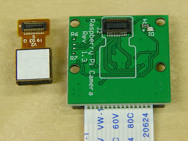
I picked up a pair of Raspberry Pi V1 cameras, both of which arrived unstuck to their breakout board:
RPi V1 camera adhesive
Requiring the customer to peel off the white layer and stick the camera to the PCB helps keep costs low. They’re $4 if you’re willing to wait two months or $7 from a “USA Seller”.