Ed Nisley's Blog: Shop notes, electronics, firmware, machinery, 3D printing, laser cuttery, and curiosities. Contents: 100% human thinking, 0% AI slop.
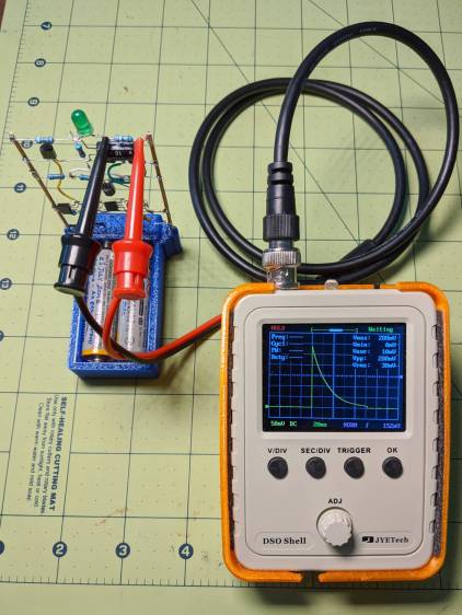
That’s a genuine JYETech DSO150 powered by an 18650 lithium cell and a boost converter set to 9 V. Make sure you get a genuine DSO150 from an authorized seller, rather than one of the myriad knockoffs; it doesn’t cost much more and tends to reward the right folks.
Anyhow, battery power means you can connect it directly across components to measure what would otherwise be a differential voltage:
LM3909 – Darl Q1 3x Q2 – 1.5 V – R1 V – DSO150
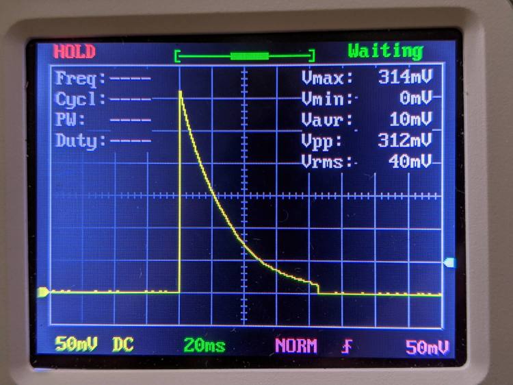
That’s the voltage across R1, the 39 Ω LED ballast resistor in the discrete LM3909 circuit running from a 1.5 V supply. Divide the 314 mV peak by 39 Ω to get 8 mA of LED current.
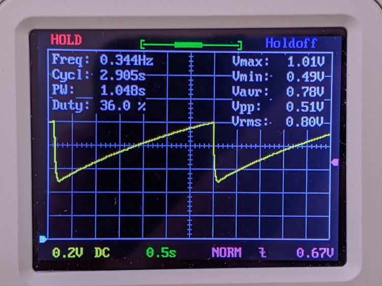
The voltage across C1, the timing and boost capacitor, looks like this:
LM3909 – Darl Q1 3x Q2 – 1.5 V – C1 V – DSO150
So the cap adds half a volt to the supply in order to put 2.0 V across the LED, which accounts for the relatively low current; the green LED has a forward drop of about 2.2 V at 20 mA and 1.9 V at µA-level current.
For completeness, the voltage across the LED:
LM3909 – Darl Q1 3x Q2 – 1.5 V – Green LED V – DSO150
So, yup, the LED really does see 2.0 V. I love it when the numbers work out.
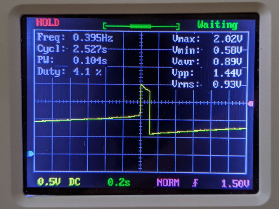
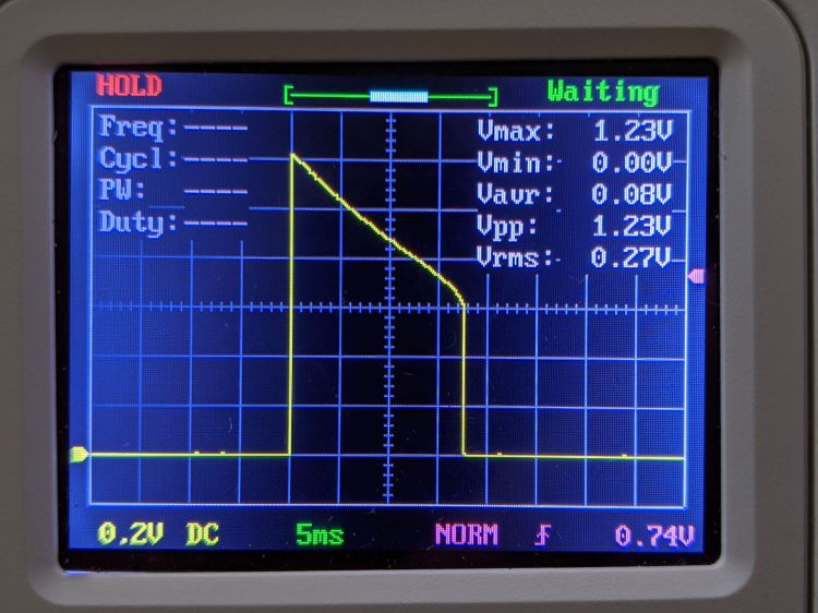
Crank the supply to 3 V and see this across R1:
LM3909 – Darl Q1 3x Q2 – 3.2 V – R1 V – DSO150
The LED current is now 1.23 V / 39 Ω = 33 mA.
The capacitor just barely enters reverse charge:
LM3909 – Darl Q1 3x Q2 – 3.2 V – C1 V – DSO150
Pop quiz: what voltage to you expect to see across the LED?
I’ll leave further investigation to your imagination, but for low-frequency analog work, you can do worse than a DSO150.
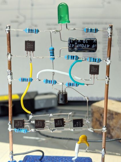
The four transistors across the bottom row let me test the simulation suggesting there’s no need for the 3× current gain mentioned in the App Note. Spoiler: future LM3909 circuits have the usual two-transistor mirror.
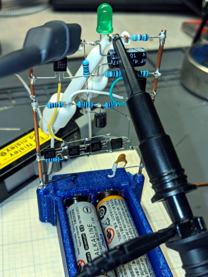
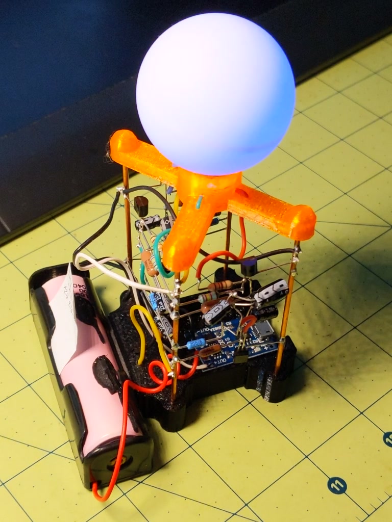
Adding some instrumentation required a bit of unsoldering and clip-lead action: to get the Tek current probe around the LED wiring:
LM3909 – Darl Q1 3x Q2 mirror – test setup
The voltage probe is across the LED, although you’ll also see the voltage across the capacitor and differential voltages measured properly with the common clip leads on the battery negative terminal. I unsoldered two of the mirror transistors after verifying a single mirror transistor can saturate Q3.
Removing the AA cells and feeding it with 3 V from a bench supply:
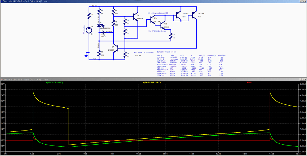
LM3909 – Darl Q1 1x Q2 – V on C1 – I 3V VCC 10 mA-div
The yellow trace is the voltage at the collector of Q3 = positive terminal of C1. The purple trace is the voltage at the LED cathode = negative terminal of C1. The fuzzy white trace is the difference of those two, showing C1 charges to about 1 V at the start of the LED flash. The white wedge over on the left marks the 0 V level, confirming the cap doesn’t enter reverse-charge territory during the flash.
The green LED produces a bright flash starting at 30 mA (bottom trace, 10 mA/div) for 15 ms. With 1 V on the cap, the LED + 39 Ω ballast resistor see nearly 4 V at the start of the pulse, because Q3 saturates around 20 mV.
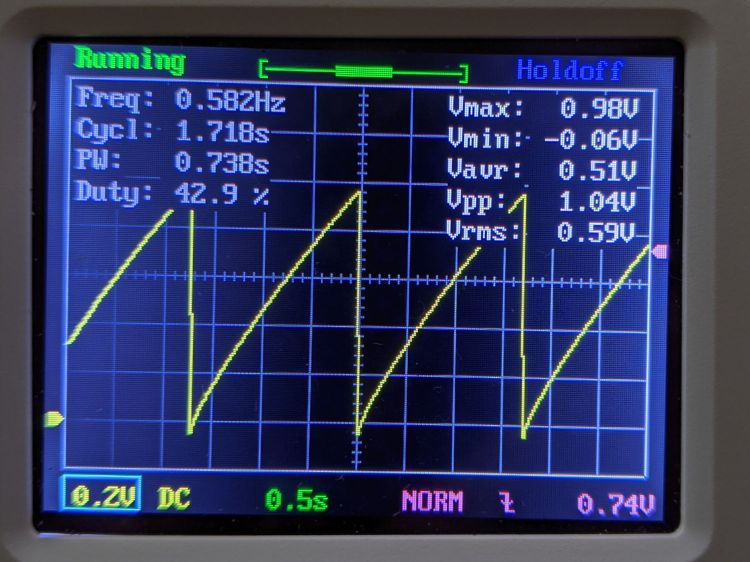
Reducing the supply voltage to 1.5 V flattens the current and lengthens the flash to 35 ms:
LM3909 – Darl Q1 1x Q2 – V on C1 – I 1.5V VCC 10 mA-div
The cap still charges to 1 V between on-times, but the lower supply puts barely 2.5 V across the LED + 39 Ω resistor and the current peaks at 10 mA. The increased duration turns the flash into a blink.
It’s good enough, so AA alkalines should last quite a while.
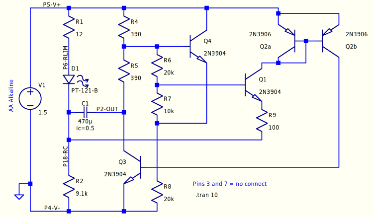
The LM3909 IC boosted a single 1.5 V cell enough to fire a red(-ish) LED, even with the cell well under 1 V. I want to blink a blue(-ish) LED from a pair of AA alkaline cells (with the right size & heft to serve as a base for the hairball circuitry), so the voltage ranges from just over 3 V down to maybe 1.5 V. Although the original circuit works, the LED pulse is long enough to put a reverse bias on the timing capacitor; a 470 µF electrolytic cap (positive terminal on the right at node P2-OUT) produces a pulse every few seconds.
A slightly tweaked version of the circuitry puts -400 mV across C1 (green trace) by the end of the pulse:
Discrete LM3909 – basic circuit – 3.0 V simulation
The App Note describes the negative feedback loop from the collector of “power transistor” Q3 through Q4 and Q1, closing through the Q2 current mirror. The base-emitter drops of Q4 and Q1 set the trip point where Q1 starts to conduct and the LED turns on.
Q3 is on when the LED is on, with C1 reverse-charging through R1 and the LED. The voltage at the top of R2 rises from the negative voltage at the start of the pulse, carrying the emitter of Q1 along with it. The LED pulse will end when the rising emitter voltage shuts off Q1 and, thus, the Q2 current mirror driving Q3. Because Q3 holds the bottom of R5 close to 0 V, the base of Q4 is at about half the supply voltage, so Q1 remains on until its emitter rises to about 2 forward drops (handwavingly ignoring the R6 + R7 voltage divider) below the supply.
If the LED pulse is longer than required to completely discharge C1, the poor cap gets reverse-biased and suffers indigestion. Aluminum electrolytics can withstand a little reverse bias, but it’s Bad Practice.
When Q3 and the LED are off, C1 forward-charges through (R4 + R5) + R2, with most of the initial voltage across R2, because C1 should start with a little more than 0 V across it. This holds the current mirror off until C1 charges enough to raise the base of Q4 about two forward drops above Q1’s emitter, shove current through Q4 and Q1, turn on the Q2 current mirror, Q3, and light the LED.
Around and around it goes!
The worst case for reverse charge happens at higher supply (a.k.a. battery) voltages and higher LED currents. Reducing the reverse charge time requires more forward drop through Q4 + Q1 to soak up the higher voltage and lower the trip voltage at Q1’s emitter, which suggests putting another forward-biased junction in series.
Putting a diode in Q1’s base lead doesn’t produce much improvement:
Discrete LM3909 – Q1 B diode – 3.0 V
Perhaps because the 27 µA current at the trip point is so low the diode doesn’t actually have much forward drop; the simulation says 400 mV.
Putting the diode in the emitter runs the current mirror’s 5 mA through it:
Discrete LM3909 – Q1 E diode – 3.0 V
The overall period remains about 2 s, but the LED pulse = reverse charge time drops by a factor of two and the cap voltage bottoms out at 0 V, so that’s good.
A Darlington transistor provides far more gain to compensate for the reduced base drive:
Discrete LM3909 – Darl Q1 – 3.0 V
The LED pulse is slightly shorter and its current goes up a smidge, but the cap voltage remains above zero.
A line in the LM3909 App Note mentions that the Q2 current mirror amplifies Q1’s emitter current by a factor of three: “This current will be amplified by about 3 by Q2 and passed to the base of Q3”. An IC current mirror’s designer can scale its output by varying the collector area, but out here in the discrete world we must splice multiple transistors in parallel:
Discrete LM3909 – Darl Q1 3xQ2- 3.0 V
More base drive in Q3 doesn’t buy much, because it’s already pretty well saturated during the pulse, but the current goes up enough to push C1 slightly into reverse charge territory again. As far as I can tell, the factor-of-three gain was required to make up for the relatively poor performance of IC technology around 1970; things have definitely improved since then.
It’s worth mentioning that the actual circuitry (in particular, the LEDs!) will differ from the simulations, so the pretty plots are more along the lines of serving suggestions than actual predictions. Verily, a simulation can’t prove that a circuit will work, but can sometimes help show why it won’t.
All the LTSpice simulation files tucked into a GitHub Gist:
This file contains hidden or bidirectional Unicode text that may be interpreted or compiled differently than what appears below. To review, open the file in an editor that reveals hidden Unicode characters.
Learn more about bidirectional Unicode characters
This file contains hidden or bidirectional Unicode text that may be interpreted or compiled differently than what appears below. To review, open the file in an editor that reveals hidden Unicode characters.
Learn more about bidirectional Unicode characters
This file contains hidden or bidirectional Unicode text that may be interpreted or compiled differently than what appears below. To review, open the file in an editor that reveals hidden Unicode characters.
Learn more about bidirectional Unicode characters
This file contains hidden or bidirectional Unicode text that may be interpreted or compiled differently than what appears below. To review, open the file in an editor that reveals hidden Unicode characters.
Learn more about bidirectional Unicode characters
The periods are much too short and the NPN astable currents much too high, but the thing runs for about ten days before the over-discharge circuit shuts it down.
So a single NPN astable driving a single-color LED with a more reasonable period should get a month or so from an end-of-life 18650 cell and a MOSFET astable might run for two months.
I’ve been using not-dead-yet lithium batteries to power astable multivibrators blinking LEDs on the red-to-yellow end of the spectrum, because the over-discharge protection circuitry in the batteries shuts down at 2.5 V, while not eking much light from LEDs toward the blue end of the spectrum.
Back in the late 60s, when integrated circuits were new, National Semiconductor designed and, in the early 70s, introduced the LM3909: “a monolithic oscillator specifically designed to flash Light Emitting Diodes”. The IC used an electrolytic capacitor as both timing element and voltage booster by charging the cap, then switching it in reverse series with the LED, to produce a voltage drop larger than the 1.5 V battery supply. The original National Semiconductor LM3909 datasheet will get you started and Application Note 154 gives more details and insight.
Rob Paisley’s work from 2008 suggested a discrete-transistor version might look just as attractive, in a techie sort of way, as the astables, and perhaps boost the 2 V from a pair of not-dead-yet alkaline cells high enough to light a blue LED.
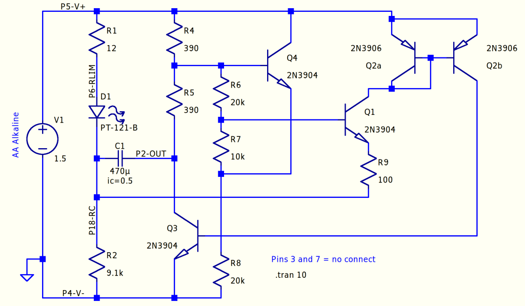
Some LTSpice twiddling produces a suitable circuit:
Discrete LM3909 – basic circuit
The labeled nodes correspond to pin numbers on the IC package, with a suffix indicating what they did for a living. R2 combines the two timing resistors in the IC into a single unit, so “P18-RC” combines the pins. The Q2 pair over on the right forms a current mirror driving Q3, which the doc calls the “power transistor”, to yank the positive end of the capacitor to ground to light the LED.
The LED is faked by a PT-121-B diode with a 2.34 V forward drop at 20 mA. It’s rated for 20 A average current, so it’s not a particularly good model for a piddly 5 mm LED, but I’ll define it to be Good Enough for now.
Running the simulation at 1.5 V is encouraging:
Discrete LM3909 – basic circuit – 1.5 V simulation
The green trace gives the voltage across the capacitor. Under these conditions, the voltage stays positive, although not by much.
Running it from a 3 V supply changes the results:
Discrete LM3909 – basic circuit – 3.0 V simulation
The cap charges to about the same voltage, but the pulse now lasts long enough to charge it nearly half a volt in the wrong direction. This is Bad Practice, even though my similarly offending astables have been doing it for years.
The data sheet points out that the forward drops of Q1 and Q2 determine the trigger level for the start of the LED pulse, so adding another forward-biased junction in series should let the cap charge to a higher voltage and, for the same pulse duration, pull the low end up above zero to increase overall happiness.
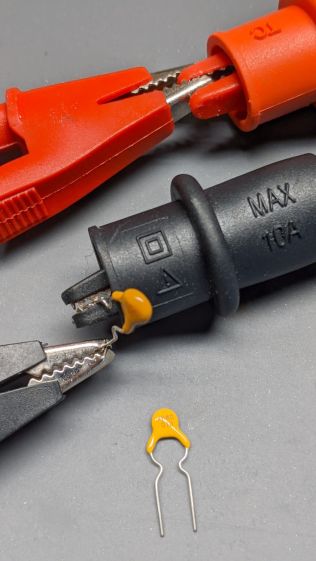
Lithium battery packs have overcurrent protection cutouts, but alkaline cells depend on their internal resistance and may overheat in response to a serious short circuit. So adding a PTC fuse to the circuitry over an alkaline battery case seemed appropriate:
Discrete LM3909 – Darl Q1 – 1X Q2 – blue LED test
That’s a test setup for a discrete-transistor version of an LM3909 LED blinker, about which more later. The PTC fuse looks a lot like a ceramic capacitor with one leg caught in an alligator clip.
Two bags of PTC fuses recently arrived from halfway around the planet, rated at 100 mA and 170 mA. One allegedly came from JinKe and the other probably didn’t pass through a Littelfuse factory despite its part number, but the only datasheet I can find is for the Littelfuse RXEF PTC PolySwitch series, which is surely close enough.
I set up a torture test involving a bench power supply and an ammeter, both offscreen and left to your imagination:
PTC Polyfuse test setup
At 75 °F:
100 mA PTC – 4.75 Ω
170 mA PTC – 2.80 Ω
With a dead short simulated by 3 V from the supply, the current stabilized at:
The datasheet says they’re good up to 60 V, but that’s just crazy talk.
The abuse put a shiny gloss on the epoxy coating, sort of like when you overcooked one of those wax-insulated capacitors back in the day.
Despite that, a PTC fuse is better than a dead short, if only because the plastic battery case won’t get all melty with the batteries supplying less than half a watt.