Ed Nisley's Blog: Shop notes, electronics, firmware, machinery, 3D printing, laser cuttery, and curiosities. Contents: 100% human thinking, 0% AI slop.
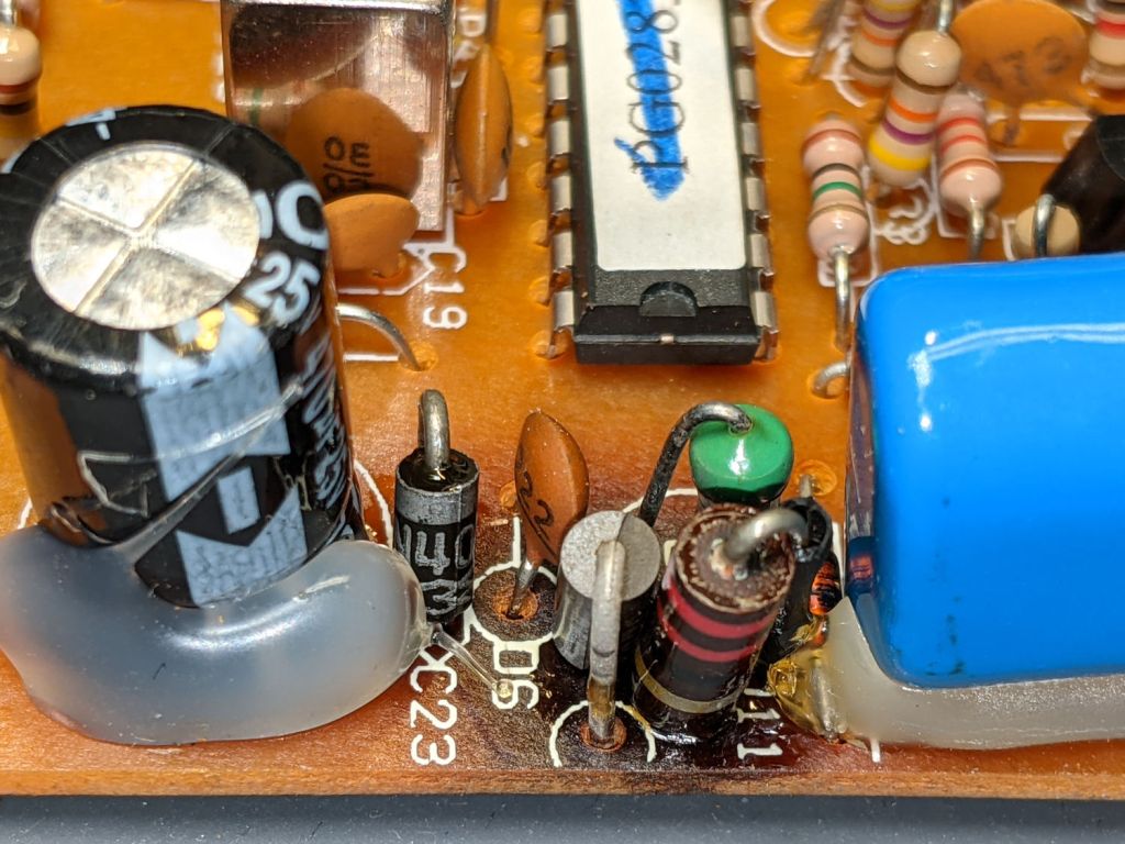
Another overheated Zener in another shunt power supply!
This BZY97C is still a diode, although I didn’t test its 68 V breakdown spec. I have no idea what they’re doing with that much juice inside an X10 RF box and have nowhere near enough interest to find out.
It still doesn’t work after a Laying On of Hands: out it goes.
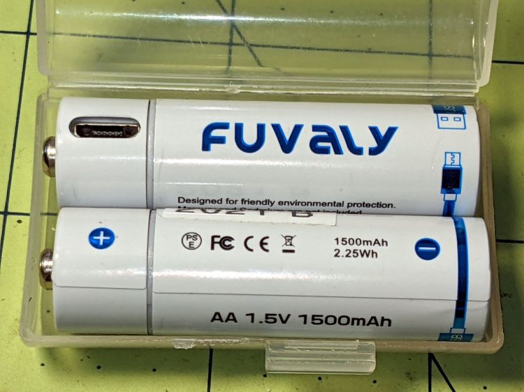
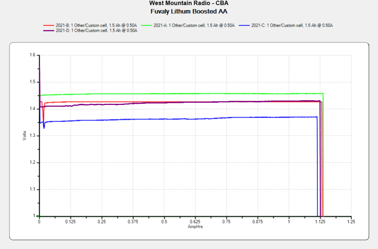
The label claims 1500 mA·h, not the 1120 mA·h I measured:
Fuvaly Bucked Li AA – mAh – 2021-02
My numbers would be higher with a load less than 500 mA. I doubt the 2.5 A maximum current rating.
The claim of 2.25 W·h is rather optimistic:
Fuvaly Bucked Li AA – 2021-02
Back of the envelope: 2.25 W·h at 1.5 V equals 1.5 A·h, all right. If you squint carefully, though, the output voltages run around 1.4 V, some of which is surely IR drop in my battery holder & test wiring, but it still knocks nearly 10% off the wattage and doesn’t seem to add to the runtime.
The camera’s battery charge indicator will obviously show Full right up until it shuts off, but I’ve always carried a spare pair of cells in my pocket anyway.
Recharging them with a USB meter in series required 425 to 600 mA·h at about 4.8 V, so about 2.5 W·h.
Enlarging the instructions from the back of the box, should they become useful:
Fuvaly Bucked Lithium AA – Instructions
Nowhere does the package mention the “brand name”, manufacturer, specifications, or much of anything substantial. I suppose anybody selling white-label products appreciates this level of detail.
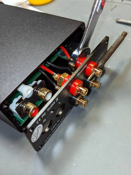
A low-end audio power amp destined for a pair of ancient-yet-still-serviceable speakers arrived, but attempting to poke wires through the side holes of the banana jacks showed they were oriented in random directions. Back in the day, banana jacks had D-shaped shafts fitted into D-shaped panel holes, but those days are gone.
A few minutes with screwdriver, wrench, and (tiny) punch sufficed to line up the holes for E-Z poking:
Fosi audio amp – jack alignment
Despite the new convenience, I decided to solder banana plugs to the speaker wires, leading to the discovery my few remaining plugs came from the very bottom of the usability barrel:
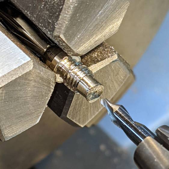
Cheap banana plug – solder side
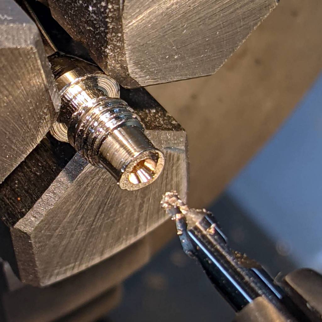
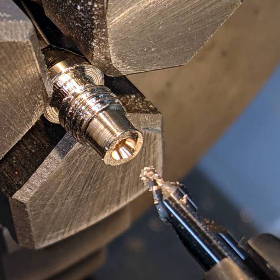
I have no idea how one might affix a wire to that blank stub, but poking a small center drill into the brass lump produces an easily solderable recess:
Cheap banana plug – center drilled
Dab with flux, tin, insert wire, add solder, repeat with all four plugs, and I’m set with a boomin’ system.
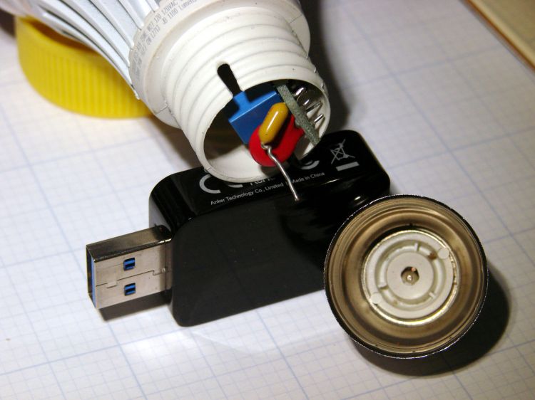
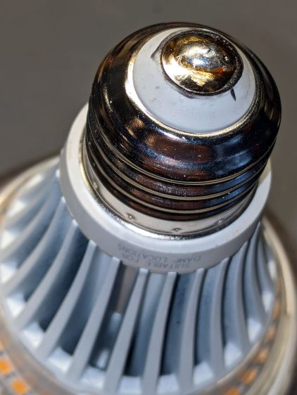
The entire metal base shell unscrewed from the plastic housing and twisted off the lead from what looks like a PTC fuse in series with the center contact; the cute little pigtail effect suggests I’ve wrecked the epoxy-to-wire seal.
It had a five year warranty which, alas, expired three years ago. This style of bulb has fallen out of favor, so I may as well get some Quality Shop Time out of it.
I don’t know how the factory machinery attached the lead to the contact button, but I’m going to go primal on it with some solder. The trick will be soldering it after assembly, so the first step is to drill through the middle of the button.
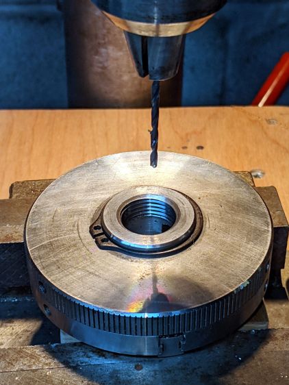
Grab it nose-down in the Sherline’s three-jaw chuck, flip it over, grab the chuck in the drill press vise, line it up, center-drill the button, then drill right through that sucker:
LED Bulb – base drilling setup
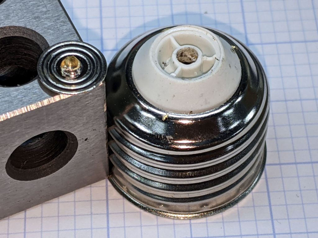
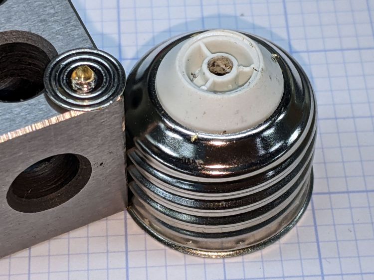
Of course, the contact came loose from the base, because I pretty much drilled right through the rivet flange holding it in place:
LED Bulb – removed center contact
Nothing a dab of epoxy can’t fix, though. I scuffed up the outside of the contact to remove the nickel (?) plating and expose the underlying brass to improve its solderability.
After the epoxy cured, align wire with hole, screw the base onto the lamp shell, and it’s ready for soldering:
LED Bulb – base ready for solder
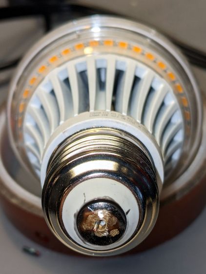
The hole is way too large for the wire, but I wasn’t about to wreck a tiny drill on what might have been a weld nugget. In any event, the bigger the blob, the better the job:
LED Bulb – soldered base
Just like light bulb bases used to look, back in the day.
With a bit of luck, it’ll sit in that socket for another seven years.
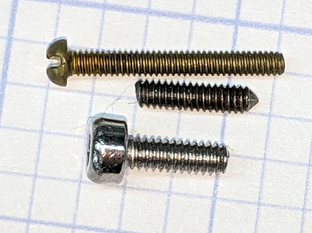
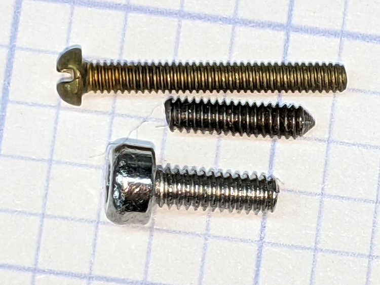
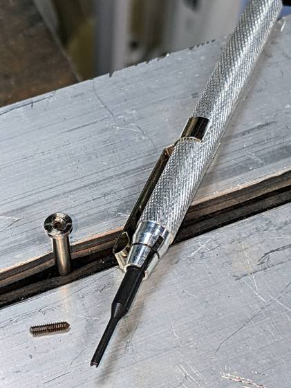
The 1-72 brass screw came heartbreakingly close to fitting and the M2 SHCS obviously won’t play. I can’t measure super-fine threads, but I can count: 16 threads on the stub occupy about the same distance as 18 threads on the 1-72 screw, so 72 × 8 / 9 = 64 tpi and it’s a 1-64 screw, not the far more standard 1-72.
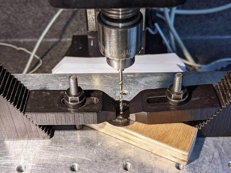
The blade hole just barely fit a #51 = 67 mil drill and measuring my assortment of mandrels produced one with the only M1.8×0.35 (OD = 71 mil) screw I’ve ever seen, so I drilled the blade with a #50 = 70 mil drill:
Gyros miniature saw blade – hole enlarging
Should the oddball screw in that mandrel break, the next step will be a #48 = 76 mil drill to fit the blade around the M2×0.4 screw for cheap and readily available mandrels.
So, being left with a broken screw stub in the original Gyros mandrel, I soaked the scene in Kroil overnight, then applied a tiny screw extractor with amazingly good results:
Gyros mandrel – broken screw extraction
I did eventually find one 1-64 screw in the Big Box o’ Tiny Screws, although its infinitesimal head seems intended for gentler duty than clamping a saw blade to the end of a whirling shaft.
Hand-held Dremel mandrels have, as far as I can tell, no particular runout specs, so chucking them in a Sherline spindle collet pretty much guarantees only a few teeth on one side of the saw will do all the cutting. Which, I hope, will suffice for my simple needs.
The red LED is actually part of an RGB Piranha, just to see how it compares to an as-yet-unbuilt version with a single red LED in the same package.
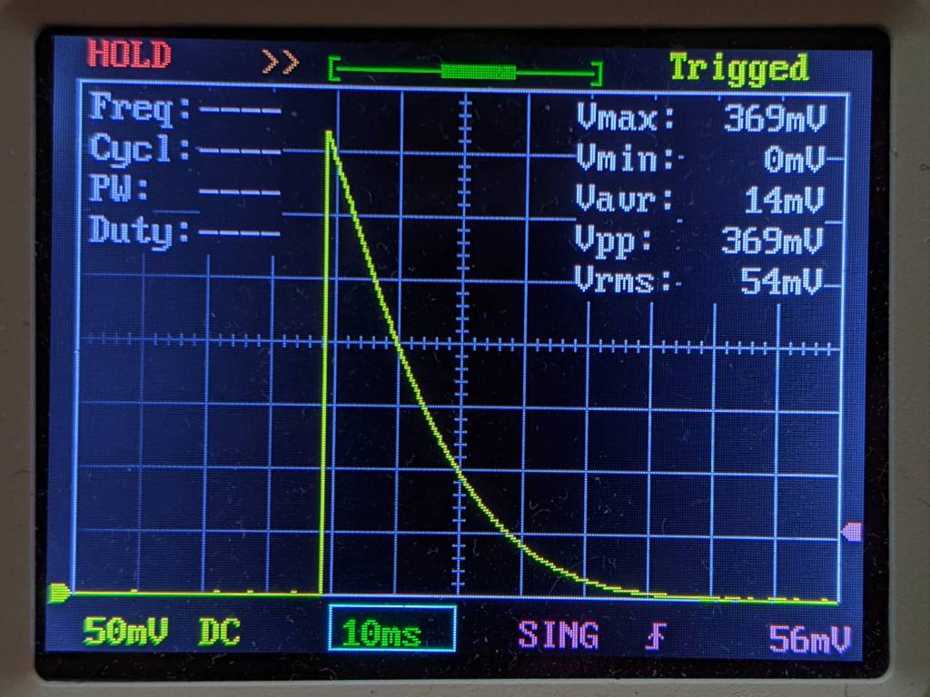
The LED drops 1.9 V of the 2.75 V from the mostly used-up AA cells:
Astable Piranha Red – 2.75 alkaline – V LED
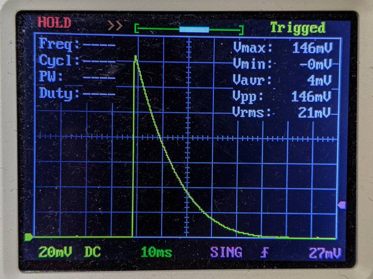
The original 33 Ω ballast resistor showed a peak current of 11 mA in a 30 ms pulse:
Astable Piranha Red – 2.75 alkaline – V 33 ohm
Replacing it with a 12 Ω resistor boosts the current all the way to 12 mA:
Astable Piranha Red – 2.75 alkaline – V 12 ohm
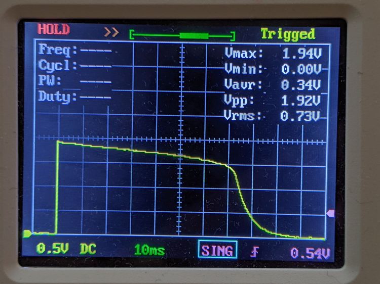
The 2N7000 gate sees a just bit more than 2 V, barely enough to get the poor thing conducting, which makes the ballast resistor mostly decorative. The MOSFET datasheet puts its 1 mA threshold somewhere between 0.8 and 3 V, so it could be worse.
Keep in mind the DSO150’s 1 MΩ input impedance sat in parallel with the 1 MΩ gate pulldown resistor forming the RC differentiator when I measured the gate voltage; I’ll leave the simulation as an exercise for the interested reader. The blinks were noticeably dimmer and perhaps a bit shorter, although eyeballometric calibration is notoriously hard.
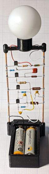
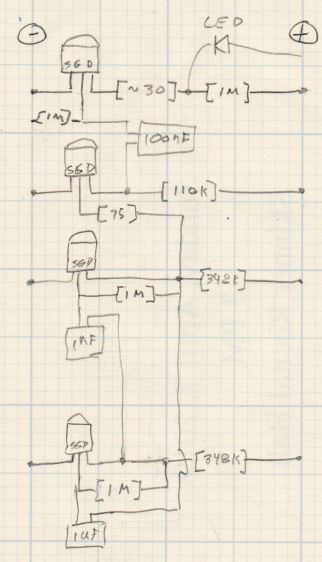
The slightly revised schematic-layout doodle stacks the transistors along the negative bus bar:
Astable wiring layout – stacked 2N7000
Flipping the bottom transistor over to snuggle the two timing caps next to each other would eliminate the long jumper wire and probably look better.
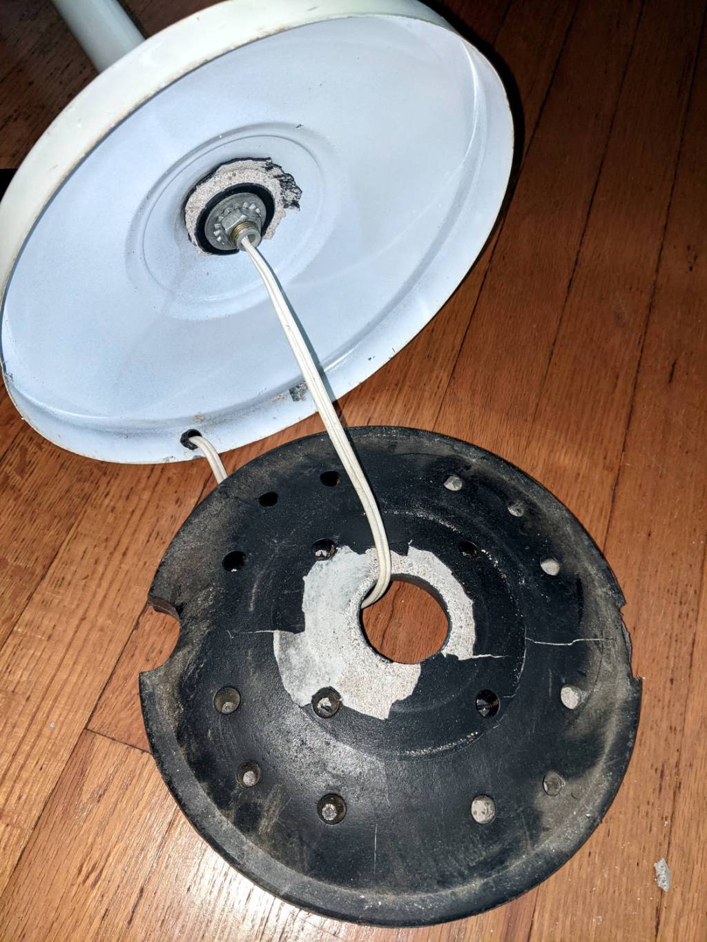
The torchiere floor lamp in the sewing room suffered a catastrophic failure:
Floor lamp – failed plastic base shell
Contrary to what you might think from seeing the shattered plastic base, we didn’t use the lamp as a club or battering ram. Apparently the designer expected the thin plastic surrounding the hole to withstand all the torque produced by the long pole against the cheap concrete / mortar / grout / whatever lump in the base. As we can recall, this lamp came to us from either a yard sale or a roadside debris harvest, so I suppose the hardware outlasted any reasonable expectation.
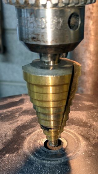
The Basement Laboratory Warehouse disgorged the pole and base from a similar lamp, albeit sporting black paint and a smaller rod connecting its pole to its somewhat larger weight. Not being too fussy about decor, I embiggened the hole in the black base to fit the white lamp’s threaded rod:
Floor lamp – enlarging replacement base
The dust on the base shows why you shouldn’t stand motionless in the Basement Laboratory for very long.
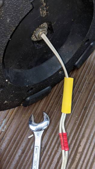
The alert reader will have noted the cord passing through a strain relief grommet in the white base. Rather than dismantle the entire lamp, I just cut the cord, ran it through the new base weight, reinstalled the washer + nut, then crimped on a pair of solderless connectors:
Floor lamp – cord splice
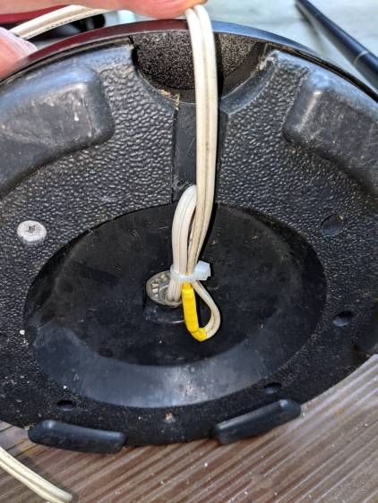
The new base doesn’t offer much in the way of attachment points, so I added a cable tie to keep the strain off the connectors:
Floor lamp – cord strain relief
A strip of genuine 3M duct tape with double-thick adhesive now traps the cord inside that small channel and, given that the lamps spends most of its time standing quietly in a corner, the cord should be fine for long enough.