Ed Nisley's Blog: Shop notes, electronics, firmware, machinery, 3D printing, laser cuttery, and curiosities. Contents: 100% human thinking, 0% AI slop.
It Would Be Nice to turn the various Raspberry Pi camera boxen around here into more-or-less full-automatic IP streaming cameras, perhaps using RTSP, so as to avoid having to start everything manually, then restart the machinery after a trivial interruption. I naively thought video streaming was a solved problem, especially on an RPi, particularly with an Official RPi Camera, given the number of solutions found by casual searching with the obvious keywords.
As far as I can tell, however, all of the recommended setups fail in glorious / amusing / tragic ways. Some failures may be due to old configurations no longer applicable to new software, but I’m nowhere near expert experienced enough to figure out what’s broken and how to fix anything in particular.
Doing RTSP evidently requires the live555.com Streaming Media libraries & test suite. Compiling requires adding -DNO_SSL=1 to the COMPILE_OPTS line in the Makefile, then letting it bake it for a while.
The v4l2rtspserver code fetches & cleanly compiles its version of the live555 code, then emits various buffer overflow errors while streaming; the partial buffers clearly show how the compression works on small blocks in successive lines. Increasing various buffer sizes from 60 kB to 100 kB to 300 kB had little effect. This may have to do with the stream’s encoding / compression methods / bit rates, none of which seem amenable to random futzing.
Another straightforward configuration compiled fine, but VLC failed to actually show the stream, perhaps due to differences between the old version of Raspbian (“Stretch”) and the new version of Raspberry Pi OS (“Buster”).
Running the RPi camera through the Video4Linux2 interface to create a /dev/video0 device seems to work, but controlling the camera’s exposure (and suchlike) with v4l2_ctl behaves erratically. Obvious effects, like rotation & flipping, work fine, but not the fine details along the lines of auto exposure and color modes.
Attempting to fire raspivid through cvlc to produce an RTSP stream required installing VLC on a headless Raspberry Pi, plus enough co-requisite packages to outfit world+dog+kitchenSink. After all the huffing & puffing wound down, the recommended VLC parameters failed to produce an output stream. The VLC doc regarding streaming is, to me, impenetrable, so I have no idea how to improve the situation; I assume RTSP streaming is possible, just not by me.
Whenever any of those lashups produced any video whatsoever, the images suffered from tens-of-seconds latency, dropped frames, out-of-order video updates, and generally poor behavior. Some maladies certainly came from the aforementioned inappropriate encoding / compression methods / bit rates.
The least horrible alternative seems to be some variation on the original theme of using raspivid to directly create a tcp stream or firing raspivid into netcat to the same effect, then re-encoding it on a beefier PC as needed. I’m sure systemd can automagically restart raspivid (or, surely, a script with all the parameters) after it shuts down.
So far, this has been an … unsatisfactory … experience, but now I can close a dozen browser tabs.
Just before midnight, the garage door opened, but, being early-to-bed folks, it wasn’t either of us. I pulled my fingernails out of the ceiling, padded out to the garage, verified there was nobody (not even a critter more substantial than a spider) inside, closed the door with the hardwired control button on the wall, and went back to bed. An hour later, the door opened again, then tried to take a bite out of me when I walked under it.
I pulled the opener’s plug, yanked its emergency release latch, lowered the door, and returned to bed; it was not a restful night.
The key to the diagnosis came from the little yellow LED on the back of the opener, just above the purple LEARN button:
Craftsman Garage Opener – indicator LED
In addition to indicating various programming states, it also lights when the opener’s radio receives a transmission from one of the remote controls. The LED was flickering continuously, showing that something was hosing the receiver with RF.
We have three remotes: one in the car, one on my bike, and one in the back room overlooking the garage. None of them worked reliably, suggesting the RF interference was clobbering their transmissions.
Disabling the remotes by removing their batteries (which were all good) also stopped the interference. Reinstalling the batteries one-by-one identified the rogue opener:
Craftsman Garage Opener – remote innards
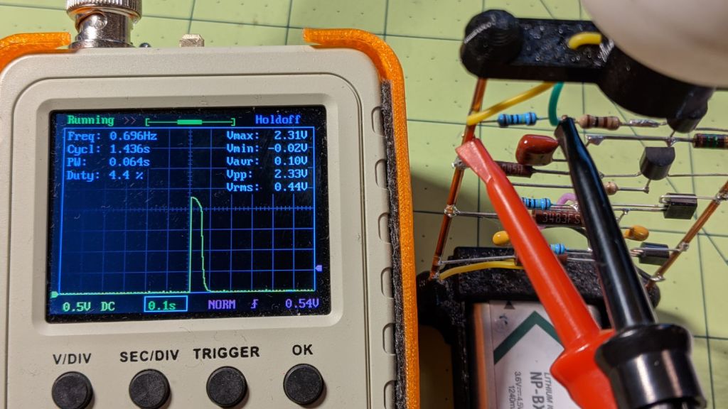
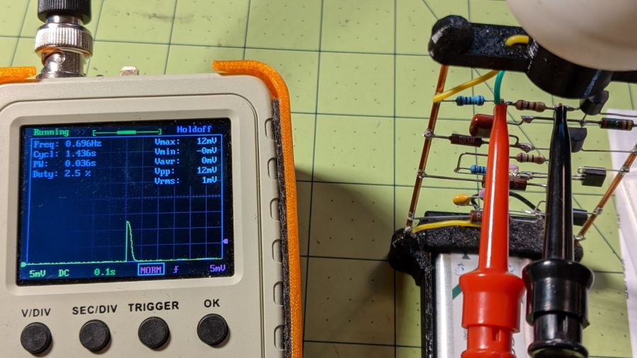
The slip of paper let me isolate the battery terminal and stick a milliammeter in the circuit, which showed the remote was drawing about 1.5 mA continuously. I thought one of the pushbutton switches had gone flaky, but swapping an unused one for the main door switch had no effect.
I lost track of which remote it was, but it lived in the car or the back room for all its life, so it hasn’t suffered extreme environmental stress. I have no idea why it would fail late one night, although I admit to not monitoring the LED on a regular basis. For whatever it’s worth, in the weeks leading up to the failure, activating the opener sometimes required two pokes at the remote, but nothing bad enough to prompt any further investigation.
A new cheap knockoff remote arrived in few days and it’s all good.
Protip: different openers, even from the same company, use different RF frequencies. For Craftsman openers, the color of the LEARN button is the key to the frequency; purple = 139.53753 MHz.
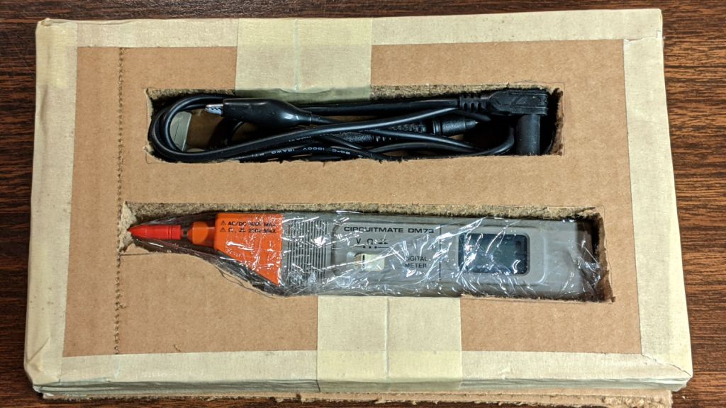
For reasons not relevant here, I sent the Beckman DM73 to a good home in Europe. Having some experience with the brutality applied to innocent packages by various package-delivery organizations, I filled a Priority Mail Flat Rate Small Box with a solid block of corrugated cardboard:
DM73 – cardboard armor
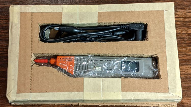
One inner layer has a cutout for the manual:
DM73 – Operator Manual package
The meter and its leads tuck into form-fitting cutouts:
Beckman DM73 – cardboard packing
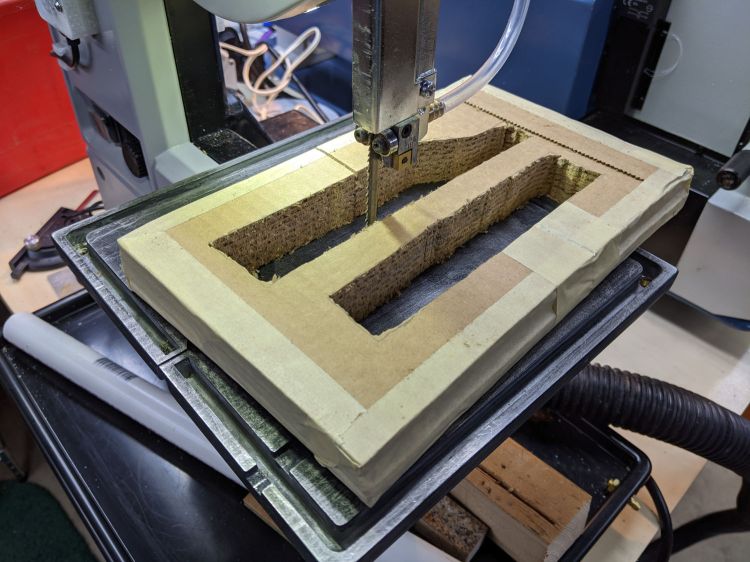
I bandsawed the cutouts from a block with enough layers for some space on the top and bottom:
DM73 – bandsawing cardboard package
After mulling that layout overnight, I made a similar block with the saw cuts on diagonally opposite corners, so pressure on the center of the edges won’t collapse the unsupported sides. A slightly larger meter cutout allowed a wrap of closed-cell foam sheet that likely doesn’t make any difference at all.
With everything in place, the box had just enough space for a pair of plastic sheets to better distribute any top & bottom impacts.
I won’t know how the armor performed for a few weeks, but it’s definitely the best packaging idea I’ve had so far.
Update: After nearly two weeks, the package arrived undamaged and the meter was in fine shape. Whew!
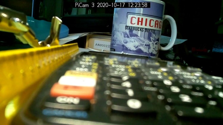
Arducam Motorized Focus Camera – desktop test range
Run the test code:
# Simpleminded focusing test for
#  Arducam Motorized Focus Camera
# Gets events through evdev from rotary encoder knob

# Ed Nisley - KE4ZNU
# 2020-10-20

import sys
import math
import evdev
import smbus

# useful functions

def DAC_from_distance(dist):
    return math.trunc(256*(10.8 + 2180/dist))

# write DAC word to camera I2C bus device
#  and ignore the omnipresent error return

def write_lens_DAC(bus,addr,val):
    done = False
    while not done:
        try:
            bus.write_word_data(addr,val >> 8,val & 0xff)
        except OSError as e:
            if e.errno == 121:
#                print('OS remote error ignored')
                done = True
        except:
            print(sys.exc_info()[0],sys.exc_info()[1])
        else:
            print('Write with no error!')
            done = True

# set up focus distances

closest = 50            # mm
farthest = 500
nominal = 100           # default focus distance

foci = [n for n in range(closest,nominal,5)] \
     + [n for n in range(nominal,250,10)]  \
     + [n for n in range(250,1501,25)]

# compute DAC equivalents for each distance

foci_DAC = list(map(DAC_from_distance,foci))

focus_index = foci.index(nominal)

# set up the I2C bus

f = smbus.SMBus(0)
lens = 0x0c

# set up the encoder device handler
# requires rotary-encoder dtoverlay aimed at pins 20 & 21

d = evdev.InputDevice('/dev/input/by-path/platform-rotary@14-event')
print('Rotary encoder device: {}'.format(d.name))

# set initial focus

write_lens_DAC(f,lens,foci_DAC[focus_index])

# fetch I2C events and update the focus forever

for e in d.read_loop():
#    print('Event: {}'.format(e))

    if e.type == evdev.ecodes.EV_REL:
#        print('Rel: {}'.format(e.value))

        if (e.value > 0 and focus_index < len(foci) - 1) or (e.value < 0 and focus_index > 0):
            focus_index += e.value

        dist = foci[focus_index]
        dac = foci_DAC[focus_index]

        print('Distance: {:4d} mm DAC: {:5d} {:04x} i: {:3d}'.format(dist,dac,dac,focus_index))

        write_lens_DAC(f,lens,dac)
Because the knob produces increments of ±1, the code accumulates them into an index for the foci & foci_DAC lists, then sends the corresponding entry from the latter to the lens on every rotary encoder event.
And then It Just Works!
The camera powers up with the lens focused at infinity (or slightly beyond), but setting it to 100 mm seems more useful:
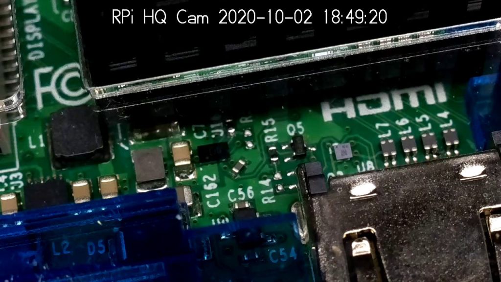
Arducam Motorized Focus Camera – 100 mm
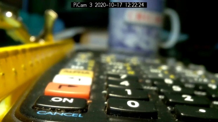
Turning the knob counterclockwise runs the focus inward to 50 mm:
Arducam Motorized Focus Camera – 50 mm
Turning it clockwise cranks it outward to 1500 mm:
Arducam Motorized Focus Camera – 1500 mm
The mug is about 300 mm away, so the depth of field extends from there to infinity (and beyond).
It needs more work, but now it has excellent upside potential!
Name:   gpio-key
Info:   This is a generic overlay for activating GPIO keypresses using
        the gpio-keys library and this dtoverlay. Multiple keys can be
        set up using multiple calls to the overlay for configuring
        additional buttons or joysticks. You can see available keycodes
        at https://github.com/torvalds/linux/blob/v4.12/include/uapi/
        linux/input-event-codes.h#L64
Load:   dtoverlay=gpio-key,<param>=<val>
Params: gpio                    GPIO pin to trigger on (default 3)
        active_low              When this is 1 (active low), a falling
                                edge generates a key down event and a
                                rising edge generates a key up event.
                                When this is 0 (active high), this is
                                reversed. The default is 1 (active low)
        gpio_pull               Desired pull-up/down state (off, down, up)
                                Default is "up". Note that the default pin
                                (GPIO3) has an external pullup
        label                   Set a label for the key
        keycode                 Set the key code for the button
Snuggle the button configuration next to the encoder in /boot/config.txt:
I haven’t yet discovered where the label text appears, because I picked a keycode defining the button as the decimal point key on a numeric keypad. Perhaps one could create a unique key from whole cloth, but that’s in the nature of fine tuning. In any event, pressing / releasing the button produces key-down / key-up events just like you’d get from a real keyboard.
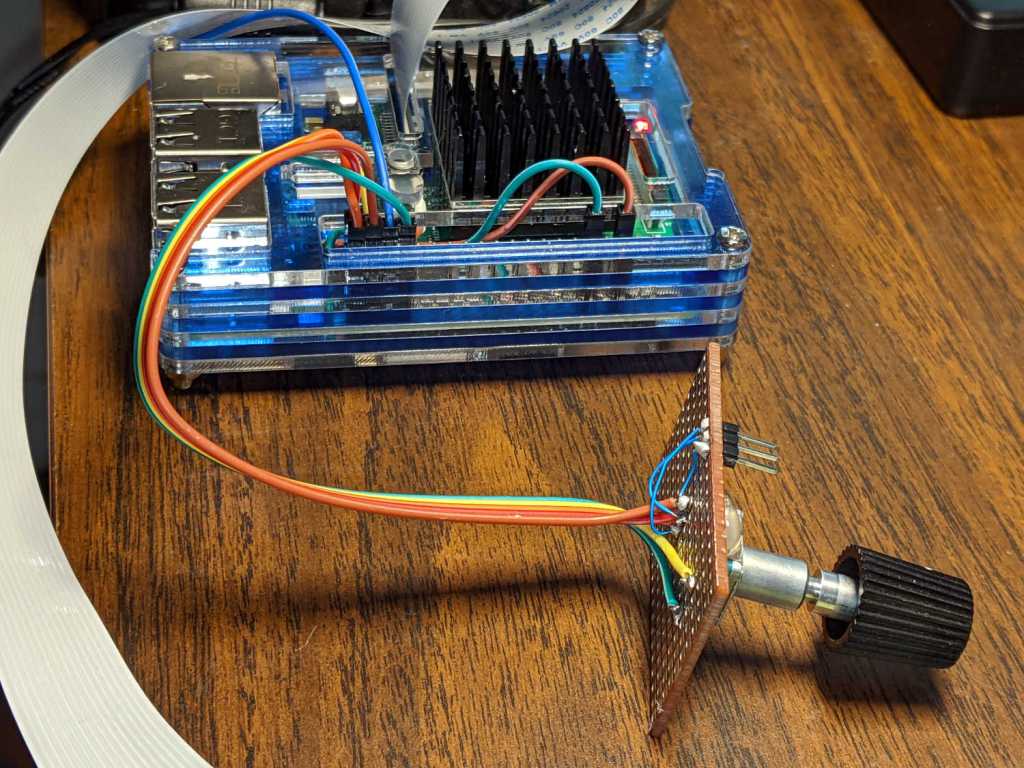
The four pins required for the encoder + switch make a tidy block at the right (in this view, left as shown above) end of the RPi’s header:
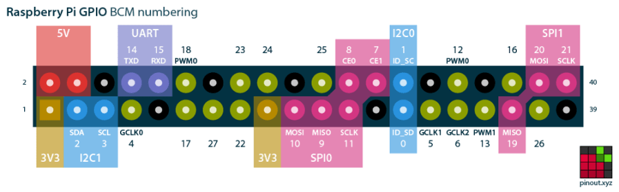
Raspberry Pi pinout
If you needed the SPI1 hardware, you’d pick different pins.
Reboot that sucker and another input device appears:
ll /dev/input/by-path/
total 0
lrwxrwxrwx 1 root root 9 Oct 18 10:00 platform-button@1a-event -> ../event0
lrwxrwxrwx 1 root root 9 Oct 18 10:00 platform-rotary@14-event -> ../event2
lrwxrwxrwx 1 root root 9 Oct 18 10:00 platform-soc:shutdown_button-event -> ../event1
As with the encoder device, the button device name includes the hex equivalent of the pin number: 26 decimal = 0x1a.
Run some code:
# Keypress from Raspberry Pi GPIO pin using evdev
# Add to /boot/config.txt
#  dtoverlay=gpio-key,gpio=26,keycode=83,label="KNOB"

import evdev

b = evdev.InputDevice('/dev/input/by-path/platform-button@1a-event')
print('Button device: {}'.format(b.name))

print(' caps: {}'.format(b.capabilities(verbose=True)))
print(' fd: {}'.format(b.fd))

for e in b.read_loop():
    print('Event: {}'.format(e))
    if e.type == evdev.ecodes.EV_KEY:
        print('Key {}: {}'.format(e.code,e.value))
Which produces this output:
Button device: button@1a
caps: {('EV_SYN', 0): [('SYN_REPORT', 0), ('SYN_CONFIG', 1)], ('EV_KEY', 1): [('KEY_KPDOT', 83)]}
fd: 3
Event: event at 1603036309.683348, code 83, type 01, val 01
Key 83: 1
Event: event at 1603036309.683348, code 00, type 00, val 00
Event: event at 1603036310.003329, code 83, type 01, val 00
Key 83: 0
Event: event at 1603036310.003329, code 00, type 00, val 00