Ed Nisley's Blog: Shop notes, electronics, firmware, machinery, 3D printing, laser cuttery, and curiosities. Contents: 100% human thinking, 0% AI slop.
Despite freezing the kitchen scraps going into the worm bin since the previous fruit fly infestation, a zillion flies are now in residence. Lacking the peppermint-stick tube of yesteryear, I conjured another fly trap from common household items:
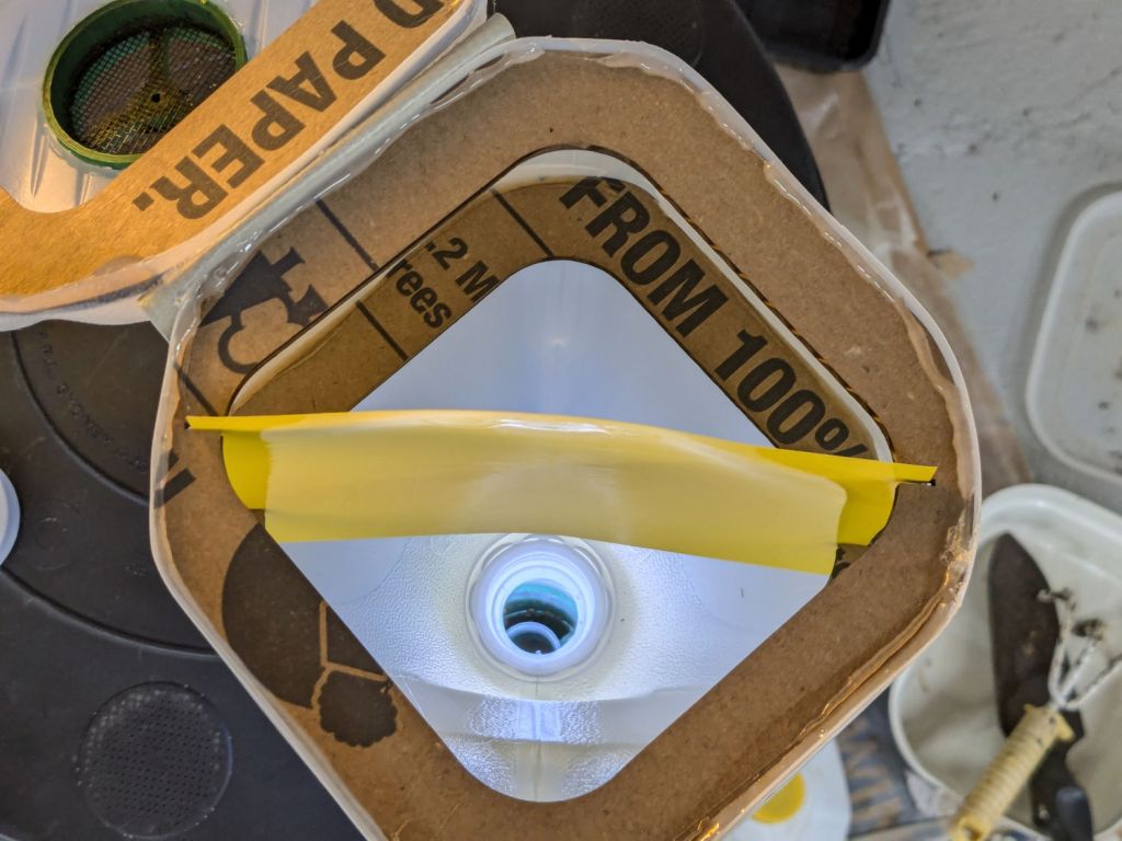
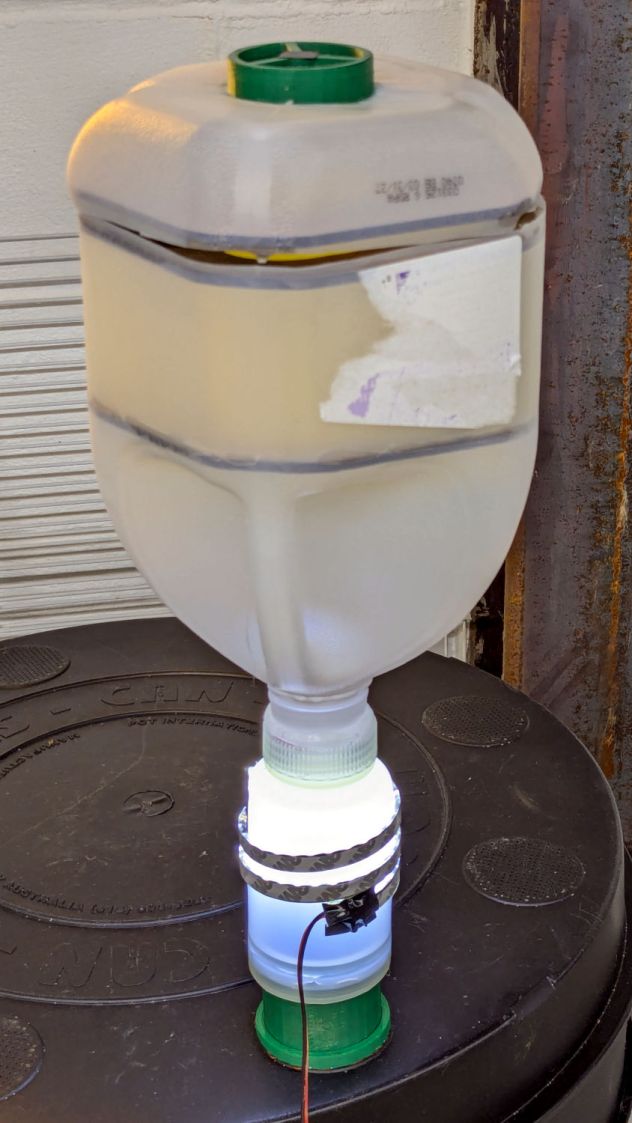
Worm Bin Fly Trap – overview
The gap around the top got a strip of tape after I took the picture.
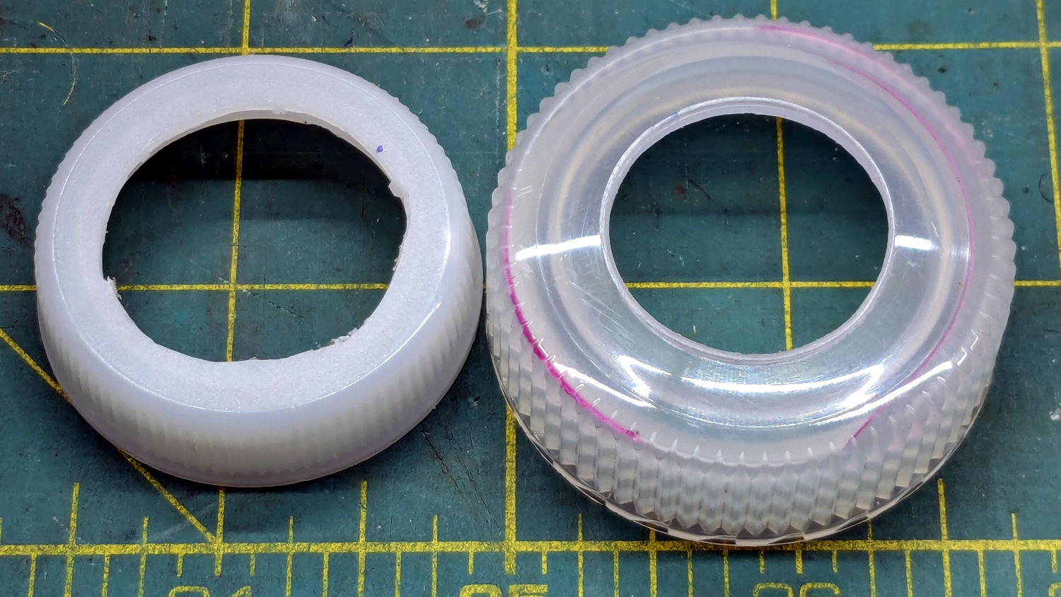
I was all set to 3D print a threaded adapter to join the two bottles when I realized they already had lids. A few minutes of lathe work added a passageway:
Worm Bin Fly Trap – Bottle caps
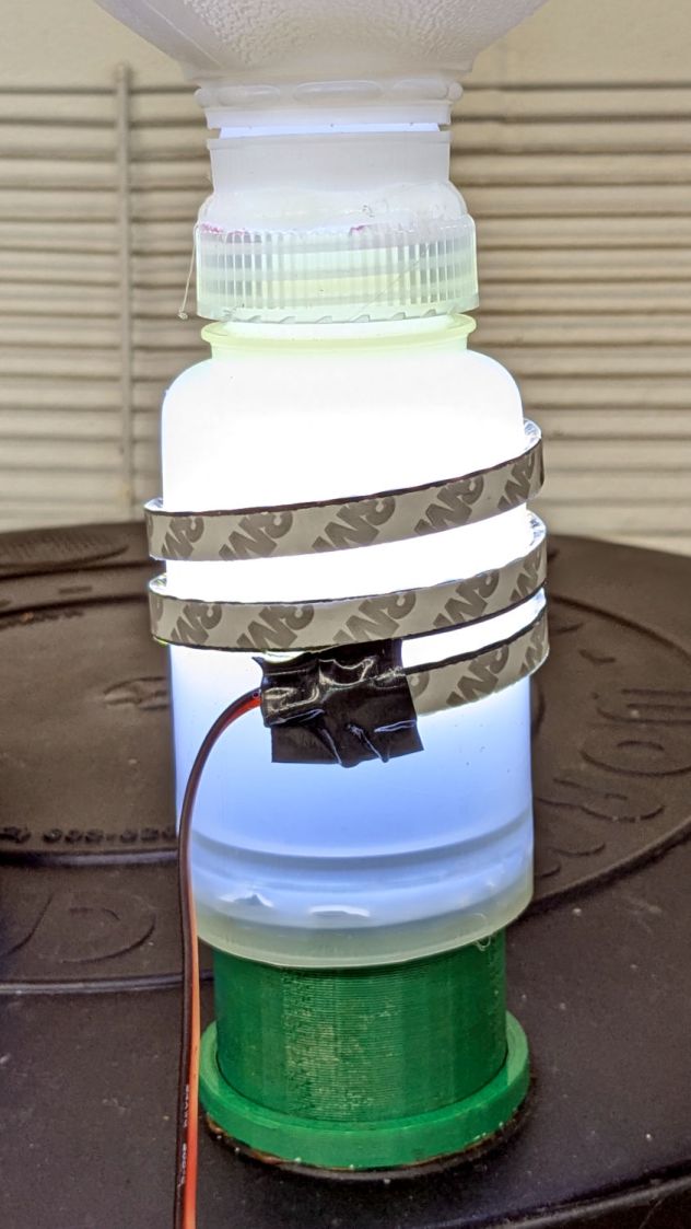
They’re held together by a generous ring of hot melt glue:
Worm Bin Fly Trap – lighting detail
The LED strip provides enough light to simultaneously attract the flies and repel the worms.
The laser cuttery looks like this:
Worm Bin Fly Trap – LightBurn parts
The white shape in the black block is a scan of the cut-open jug, with the other shapes in that row being rectangularized versions. The two tiny notches in the Top and Bottom shapes hold the sticky paper.
The two rings at the top adapt the LED-wrapped bottle to the existing fitting on the worm bin from the previous episode. They’re visible as shadows near the bottom of the bottle.
The circle is a laser-cut hole in the gallon jug bottom for the screened plug made for the pepermint-stick tube; the less said about that operation the better.
So far, so good, although previous experience suggests the flies will be breeding ahead of their (considerable) losses for the next few weeks.
Mary reported a problem unplugging the USB charger powering the light pad (the successor to the pad I repaired) she uses for quilting layouts:
USB Charger – as found
Yes, that blade is sticking out of the hot (“Line”) side of the outlet.
The only way into the charger was through its other end:
USB charger – interior top
Because I had no intention of returning it to service, I tried pushing the errant blade back in place, only to have it overshoot the mark and bulldoze various parts aside:
USB charger – PCB blade contacts
The two upright shapes contact the blades, but do not lock them in place. The PCB pulled easily out of the case, with no objection from the remaining (“Neutral”) blade.
The blades are simple steel bars press-fit into the plastic case, without holes / dimples / notches to lock them into the plastic. As far as I could tell, they were not molded in place.
I tossed the corpse into the e-waste box, extracted another USB charger from the Box o’ USB Chargers and returned the light pad to service.
I do have a few Genuine UL Listed USB chargers, but these are not among them.
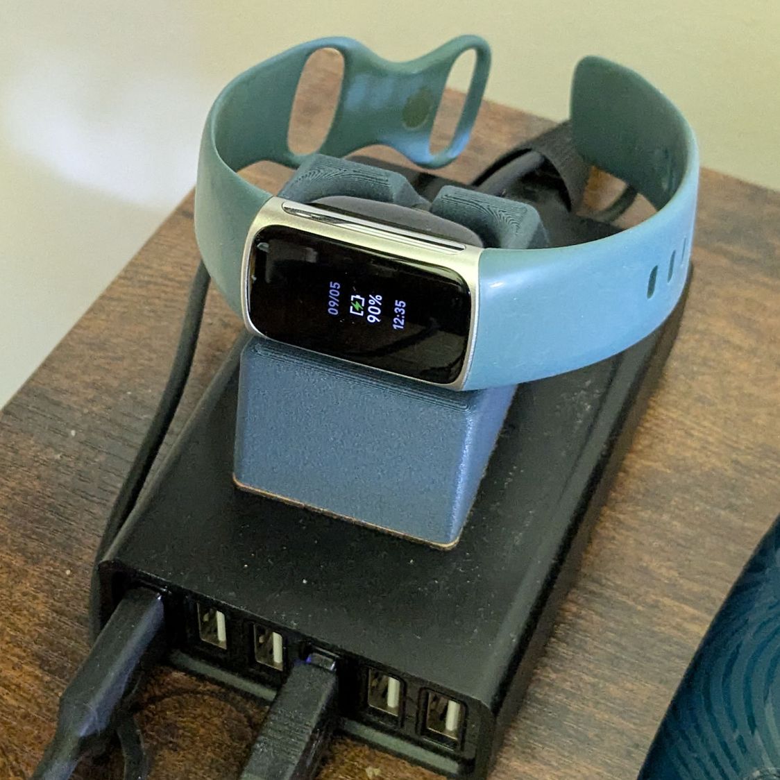
My Fitbit Charge 5 has become fussy about its exact position while snapped to its magnetic charger, so I thought elevating it above the usual clutter might improve its disposition:
FitBit Charge 5 stand – installed
The Charge 5 now snaps firmly onto its charger, the two power pins make solid contact, and it charges just like it used to.
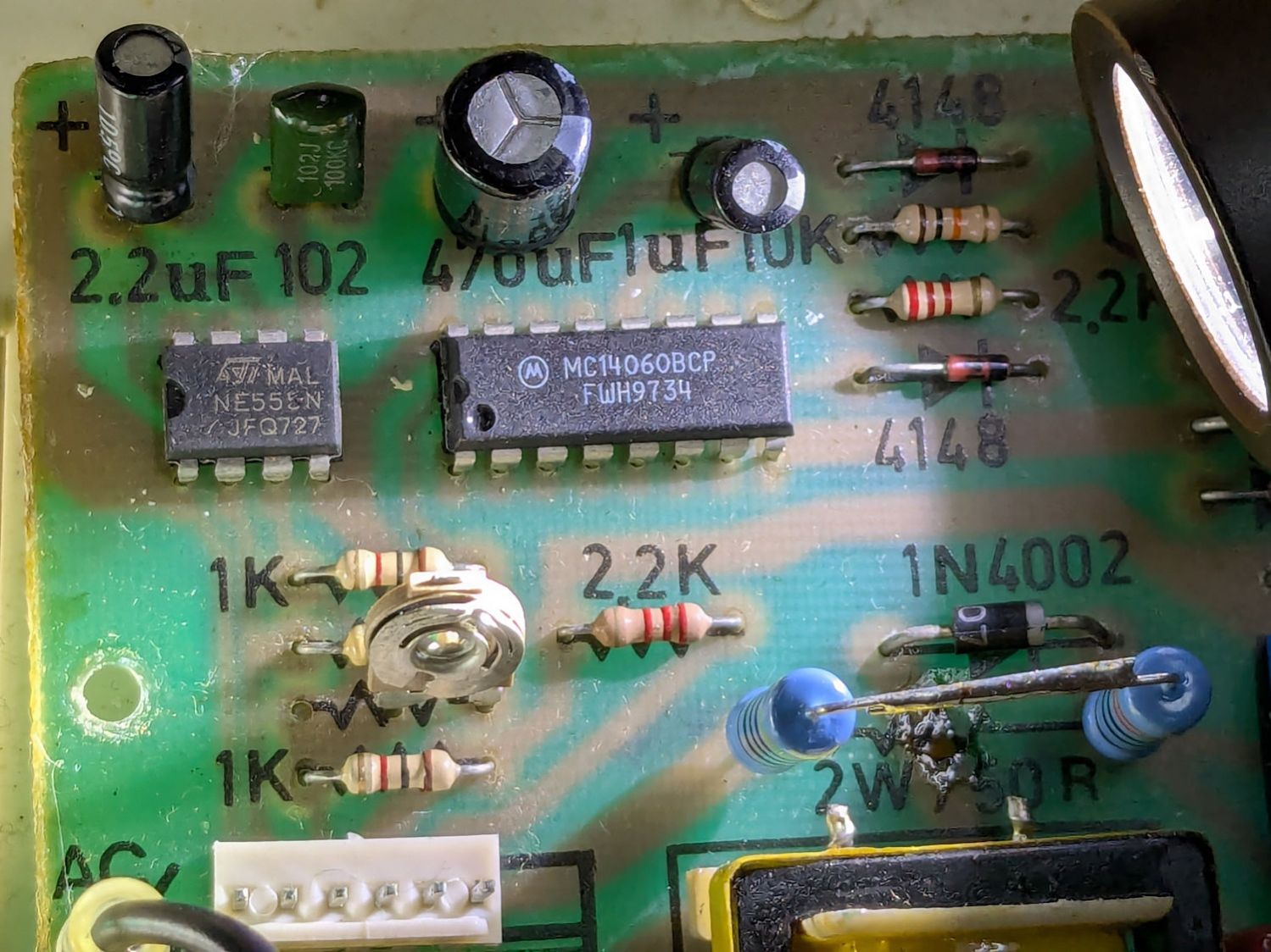
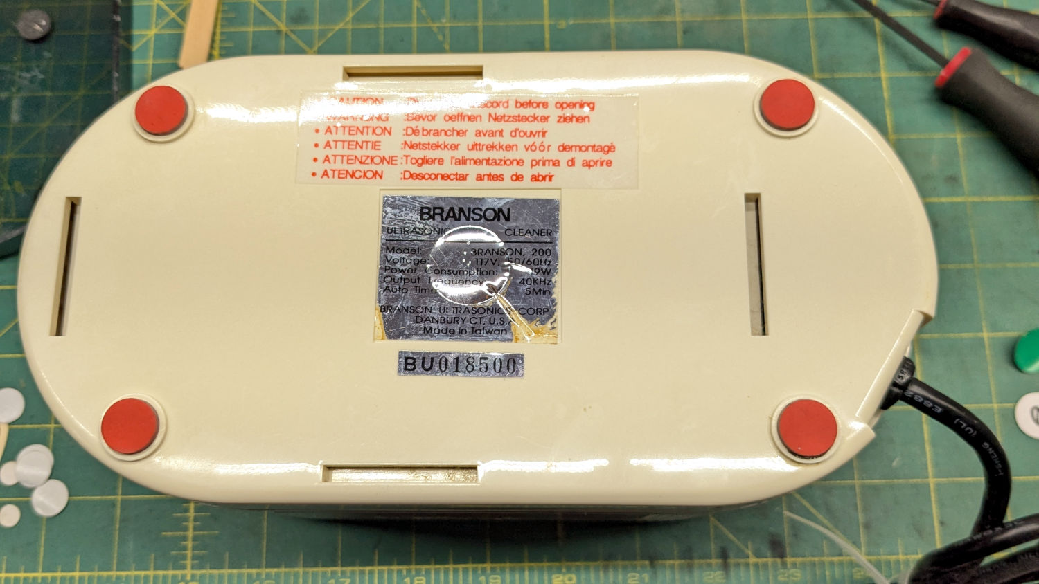
The Branson 200 ultrasonic cleaner in the bathroom has been with me for a long time. If I’m reading the IC date codes correctly, it’s one of the first things I bought after real paychecks began arriving back in 1974:
Branson 200 ultrasonic cleaner – IC date codes
The circuit board has that spacious old-time layout:
Branson 200 ultrasonic cleaner – PCB overview
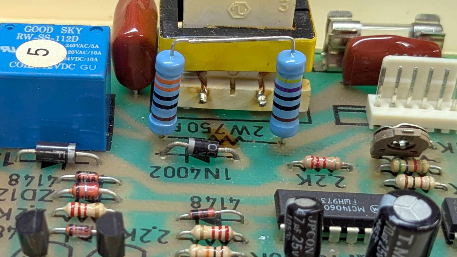
Believe it or not, this isn’t why I took the thing apart:
Branson 200 ultrasonic cleaner – charred resistor
I’ve never seen a PCB with the component values printed on it, but they definitely came in handy!
That resistor measured 743 Ω: still good, even with an extra-crispy coating.
Assuming it was dissipating a bit more than its 2 W rating could handle, I replaced it with a 470 Ω + 330 Ω series combination of 2 W 1% metal film resistors:
Branson 200 ultrasonic cleaner – retrofit resistors – top
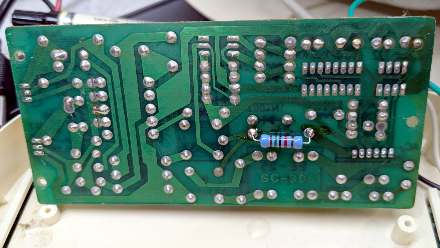
In parallel with a 15 kΩ resistor on the back of the PCB to bring them down to 759 Ω:
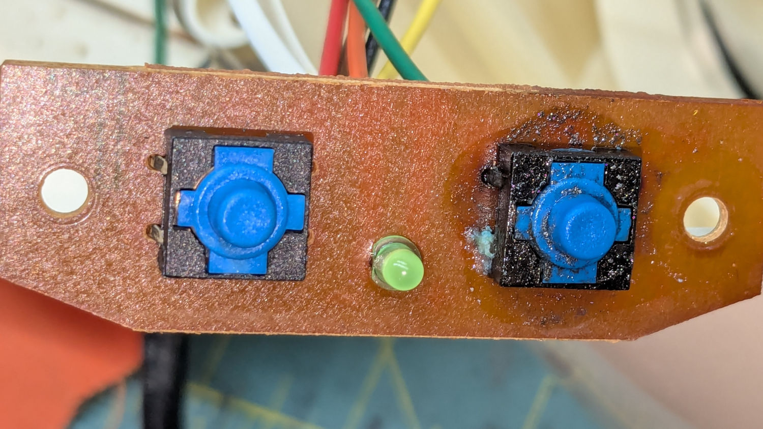
Well, almost perfectly. The original case holes were a snug fit around a 25/64 inch = 9.8 mm drill , so I hand-twisted X and Y drills (10.1 and 10.3 mm, respectively) to embiggen the holes for a loose fit around the new switches.
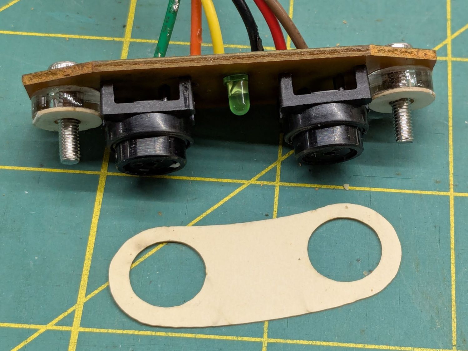
The two small plastic disks + paper shims hold the PCB just far enough away from the case to put the switch actuators flush with the case surface, with 12 mm M3 SHCS replacing the original 6 mm screws.
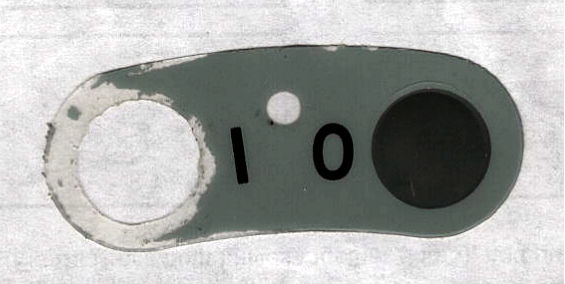
The cardboard test piece came from the usual scan of the original switch cover and, after a few iterations, we now have a stylin’ paper replacement:
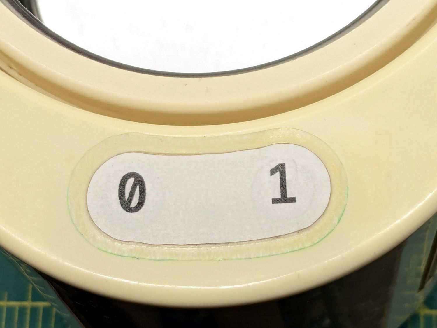
The transparent cover with greenish edges is transfer tape intended for vinyl sheets, which will likely not survive very long at all. It’s outset 3 mm from the paper label, just barely enough to get any traction at all on the case.
While I was at it, I replaced the worn black rubber feet with fancy red stamp-pad rubber feet:
For the record, only two screws secure the top & bottom parts of the case. They’re on the power-cord end of the bottom, so those are the only two feet you must peel off to get inside.
All of which put the cleaner back in operation while I figure out what kind of tape will seal the power switches more permanently.
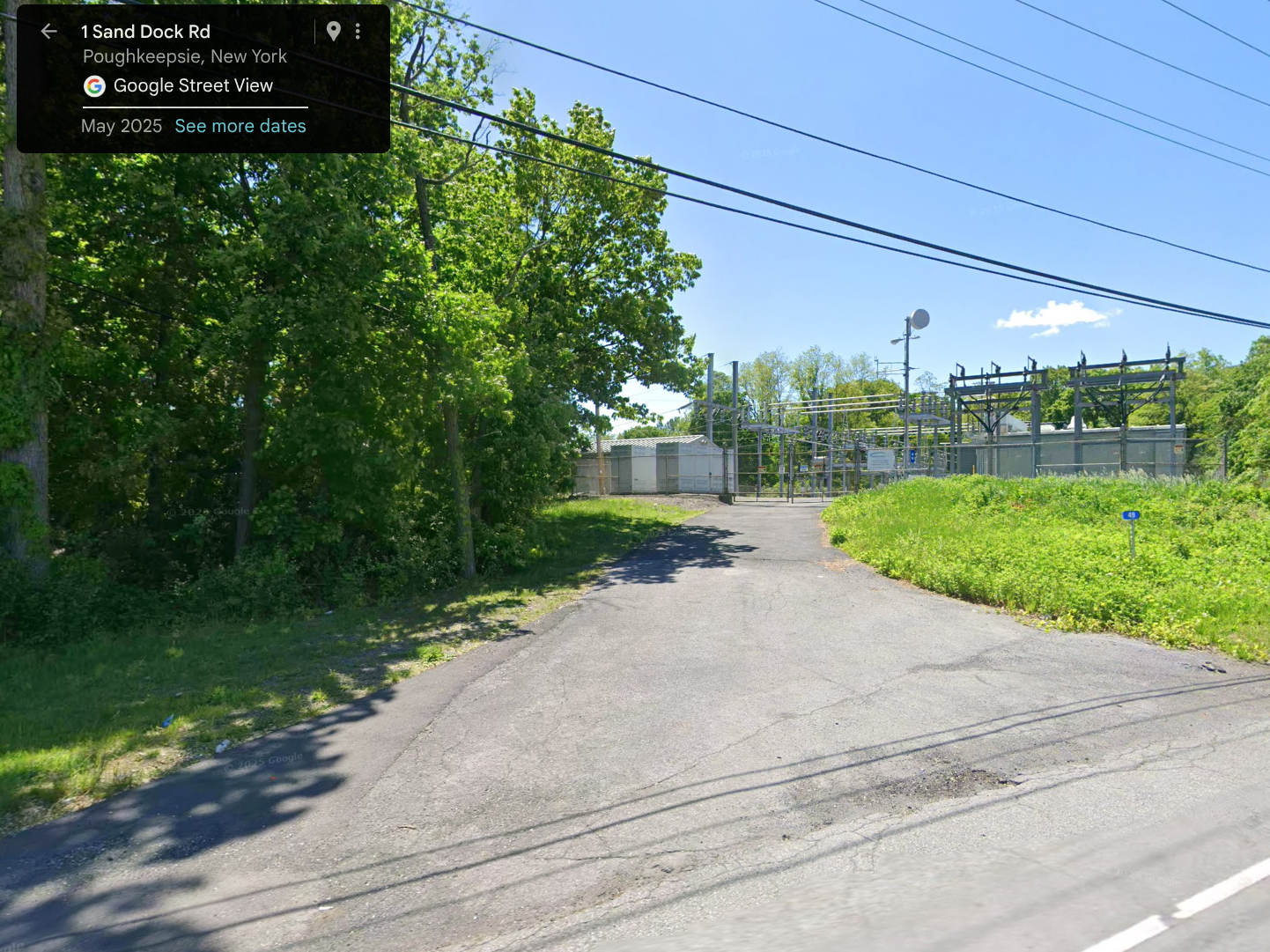
For reasons not relevant here, I walked along IBM Rd to the end of Sand Dock Rd and back, passing the switchyard serving the IBM Poughkeepsie site:
Street View – 1 Sand Dock Rd
The overall capacity is surely in the tens of megawatts and there’s an overwhelming hum coming down that driveway:
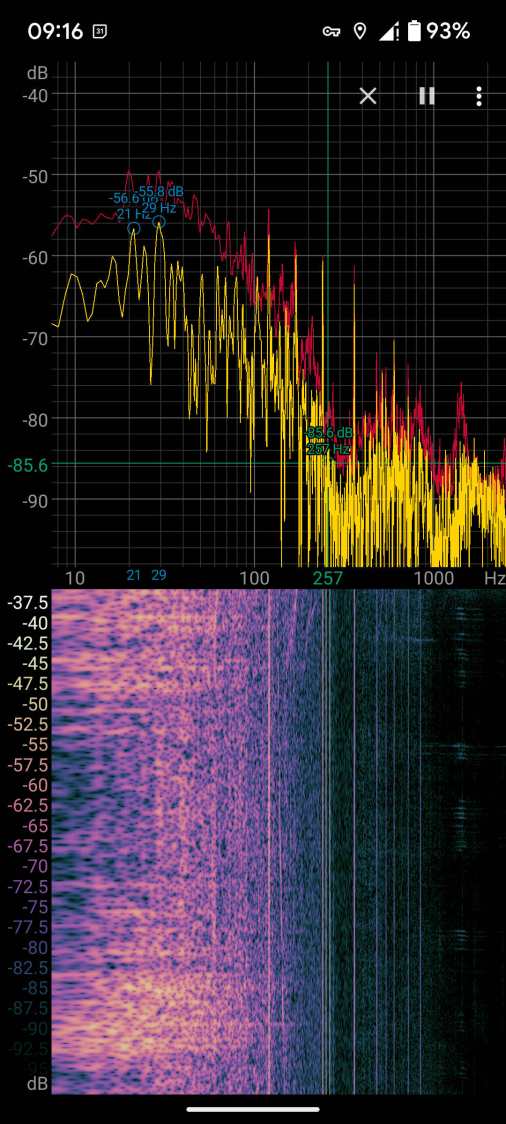
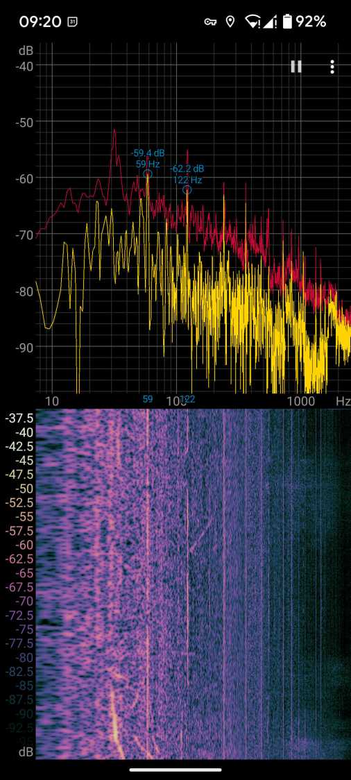
Switchyard hum
Those peaks and the corresponding lines in the waterfall show the equipment emits acoustic energy all the way up to about 480 Hz, call it the eighth harmonic of 60 Hz.
Transformer steel has low magnetostriction, which produces most of the noise at even harmonics of the 60 Hz power line (because each cycle has two current maxima). The spectrogram shows the switchyard handles enough current to emit plenty of odd harmonic energy, with a notable peak at 180 Hz.
For comparison, standing a few feet from the transformer behind a medical office building along IBM Rd:
Transformer hum
No 180 Hz energy from that transformer!
Moving a few feet further away dropped those peaks into the background.
Even with my deflicted ears, I think can hear the switchyard hum from a considerable distance along the road, so maybe the background isn’t as quiet as I think.