Ed Nisley's Blog: Shop notes, electronics, firmware, machinery, 3D printing, laser cuttery, and curiosities. Contents: 100% human thinking, 0% AI slop.
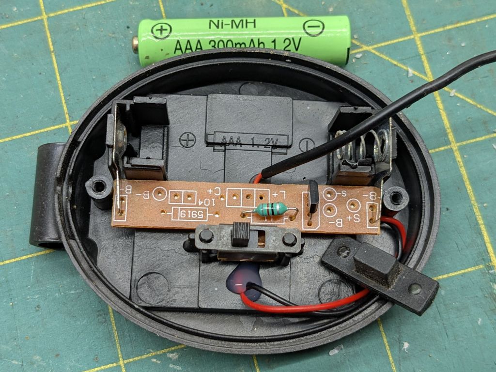
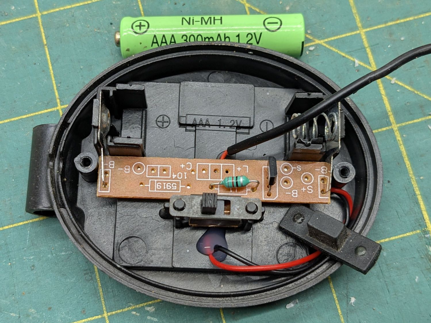
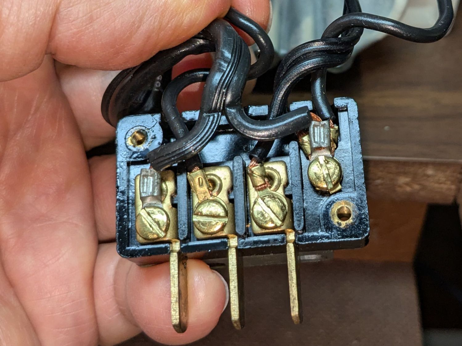
For the record, this is inside the machine’s power connector:
Kenmore 158 – power connector wiring
Power for the original glowworm incandescent light comes from the two rightmost terminals: 120 VAC switched by the machine’s power button. Those terminals now go to a new, much more flexy, cable for the 12 VDC power supply, with a step-up supply for the needle LEDs.
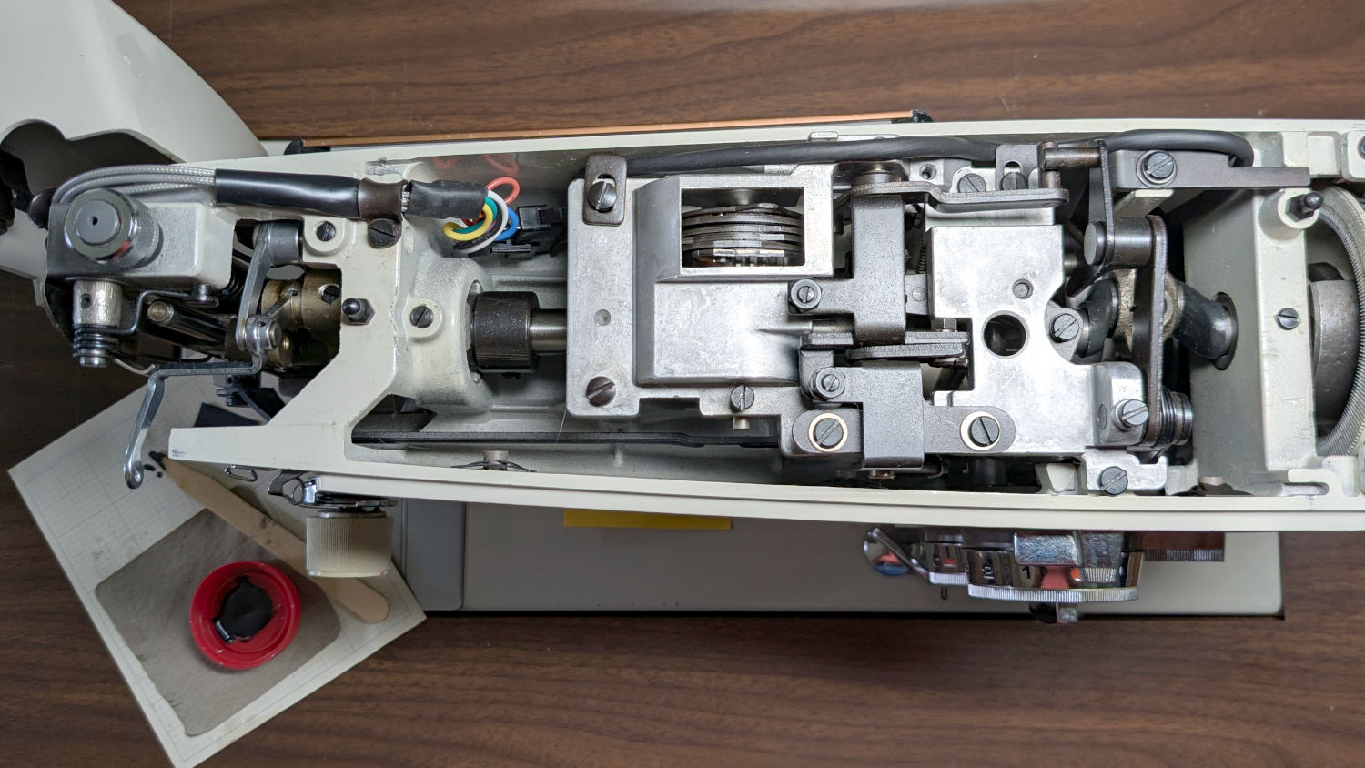
An overview of the wire routing:
Kenmore 158 – COB LED wire routing
There’s now a 9-pin JST SM connector between the repurposed serial cable and the LEDs, mostly so I can add another light bar to the front in the unlikely event it becomes necessary.
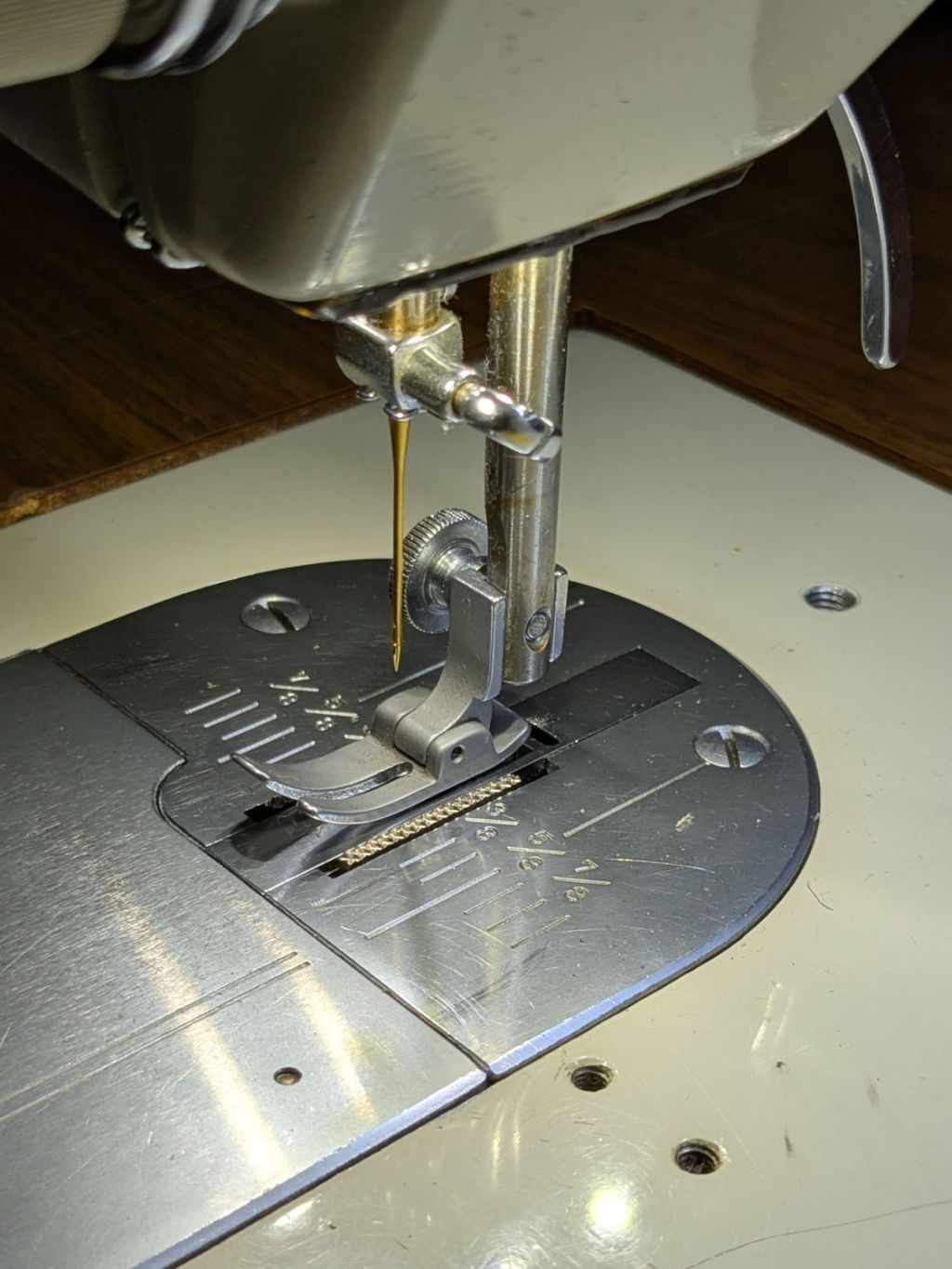
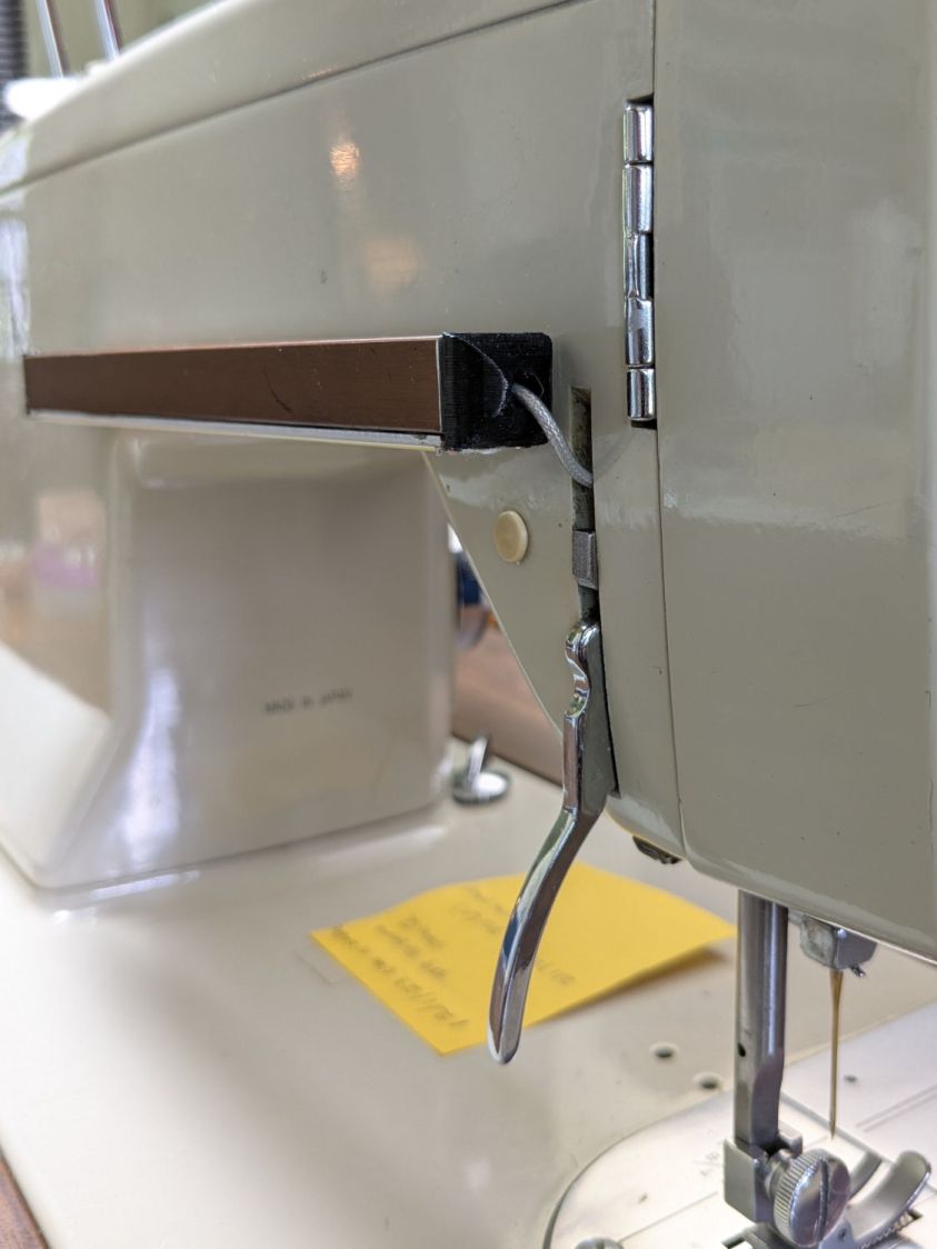
The rear light bar wire once again burrows into the machine above the presser foot lever:
Kenmore 158 – COB LED bar wire routing
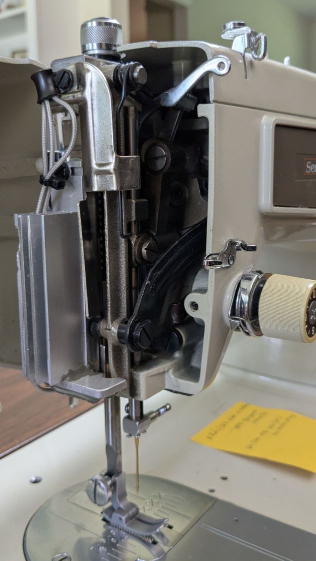
All the LED wiring fans out through the endcap:
Kenmore 158 – COB LED needle heatsink
You can just barely see the edge of the strip of LEDs epoxied to the bottom of the machine nose, on the right of the needle.
If I were inclined to rebuild the needle LEDs, I’d use flexy silicone wiring instead of the Teflon insulated coax. The black insulation wouldn’t be nearly as pretty, but it’d be *way* easier to cut to length and solder.
The patient survived the operation and sewing should resume shortly …
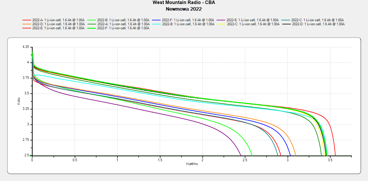
I don’t know what the bump in the middle of the new battery discharge curve means. Something weird in the chemistry, I suppose. Getting good batteries from Amazon surely remains a crapshoot and I now have four chargers.
Recharging all six batteries required 5488 mA·hr, just over 900 mA·hr apiece. Running the camera on a one-hour bike ride burns 600-ish mA·hr, so that’s comforting.
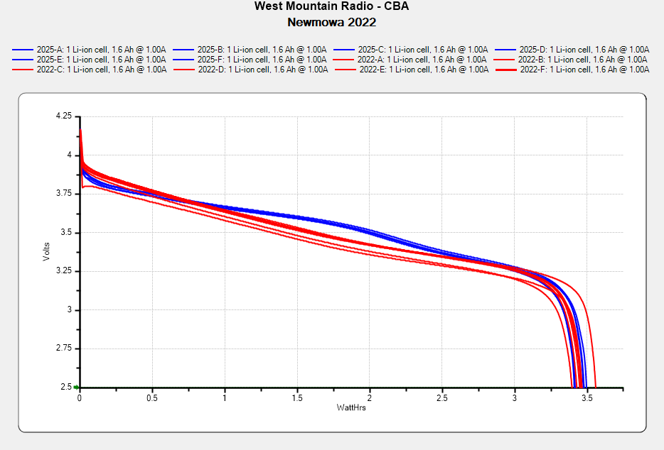
Comparing the new results with the 2022 batteries tested last month:
NP-BX1 – Newmowa 2022 in 2025-06
The upper traces appear in red in the first plot, the lower curves come from three years of use.
The best four have a capacity down 14% from the good old days and the weakest pair are down 29%.
The camera uses 1.9 W, so a battery with 2.5 W·hr capacity should last 78 minutes, but about 400 mV of voltage depression causes the camera to give up before using its full capacity.
So they have a useful lifetime of maybe two years in our regular bike riding schedule and I should have bought replacements last year. I hope the next batch isn’t New Old Stock or recycled cells.
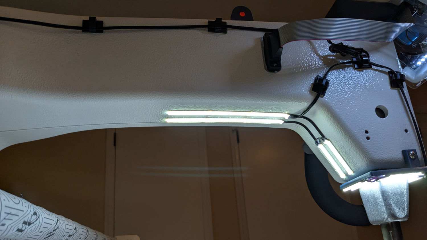
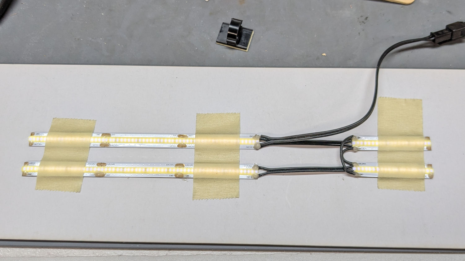
With the nose ring lights in place, I soldered up eight more 24 V LED strips to light the quilt under the HQ Sixteen’s arm:
HQ Sixteen – under-arm lights – bottom view
A simple fixture aligned the strips for soldering:
HQ Sixteen – under-arm lights – soldering fixture
I intended to peel the masking tape off the glossy cardboard, then use it to keep the strips aligned while I pressed the PSA adhesive on the back of the strips to the machine. The silicone molded over the LEDS turned out to be supremely un-stick-able to the tape and the strips got far more handling than I planned, but I think the adhesive will work.
The cable from the power supply now has a pair of JST SM connectors on the end. Although crimping two conductors into the same pin is not good practice, all 14 of the LED strips draw an aggregate of maybe 130 mA, so I think it’ll suffice.
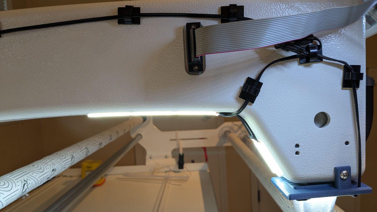
The JST connectors hide behind the ribbon cable going to the machine’s front panel, so there’s not a lot of basis for arguing they’re unsightly:
HQ Sixteen – under-arm lights – side view
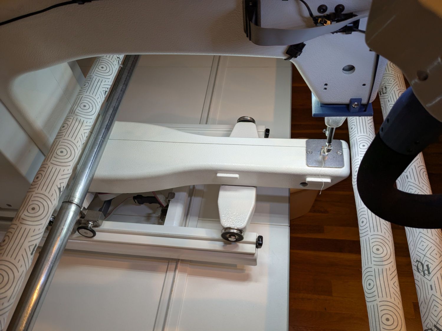
The finished part of the quilt passes under the bottom bar on the left (the rear of the machine table) and forms an ever-increasing roll around the top bar; the white fabric leader attaches to the edge of the quilt. The LED strips illuminate the in-progress part of the quilt under the arm and should be far enough forward to not snag on the rolled-up finished part.
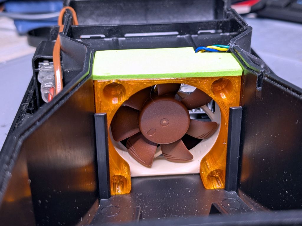
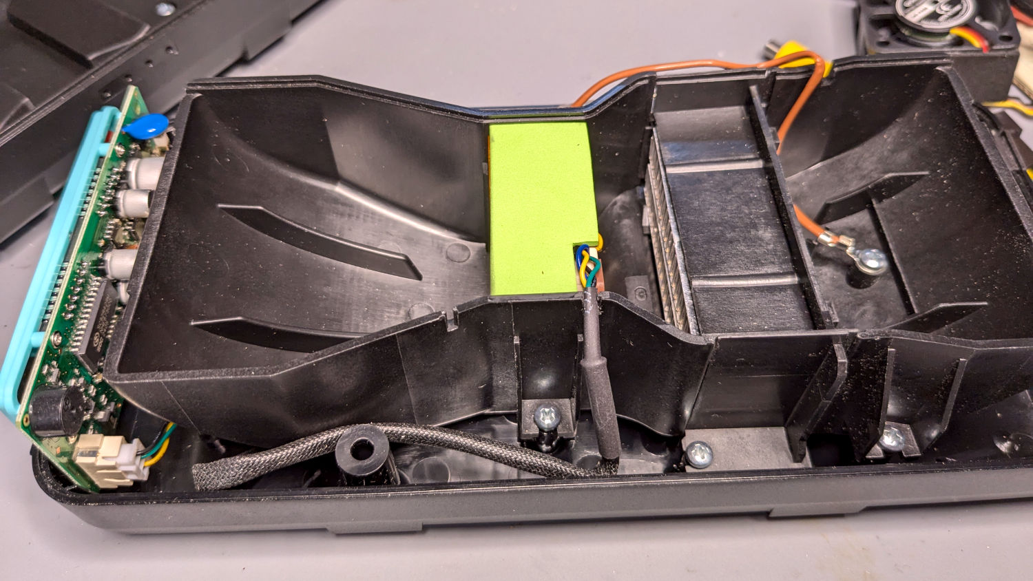
The OEM fan inside the PolyDryer is annoyingly loud, even to my deflicted hearing, so I printed a Noctua NF-A4x10 fan adapter and installed a much quieter fan:
PolyDryer – Noctua fan installed
The adapter is upside-down from the suggested orientation, I didn’t bother screwing it to the fan because it has sleeves fitting into the fan screw holes, the slot holds everything together, the vivid green EVA foam sheet sits atop a craft adhesive sheet (both cut with scissors!) ensuring they don’t part company, and it works just fine.
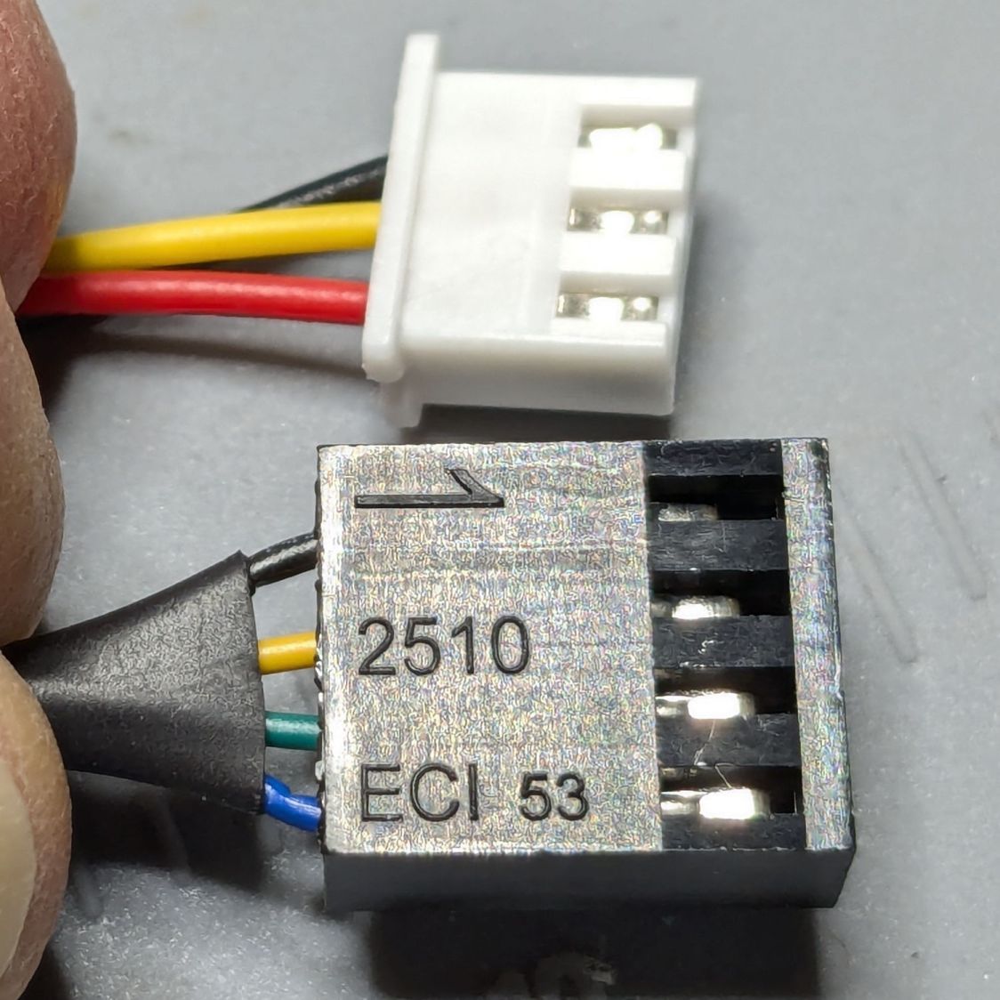
Of course, the OEM fan has a three-wire cable and the Noctua has a four-wire cable:
PolyDryer – OEM vs Noctua fan cables
Although you can’t quite make it out on the white plastic, both connectors have their Pin 1 marks adjacent to each other. I oriented them like that to put the pin release latches on top; a foolish consistency is the hobgoblin of small minds.
Fortunately, Noctua documents their pinout, a bit of probing verified the OEM fan pinout (which does not match the Noctua 3-wire pinout), and the Basement Warehouse Wing emitted an assortment of matching JST XHP connectors. Chop off the black connector and rewire it in a 3-pin XHP connector:
Pin 1 = OEM Red → Noctua Yellow = +24 V
Pin 2 = OEM Yellow → Noctua Green = Tachometer
Pin 3 = OEM Black → Noctua Black = Ground / Common
unused = Noctua Blue = PWM Speed Control
Which is barely visible plugged into the control PCB on the left:
PolyDryer – Noctua fan wiring
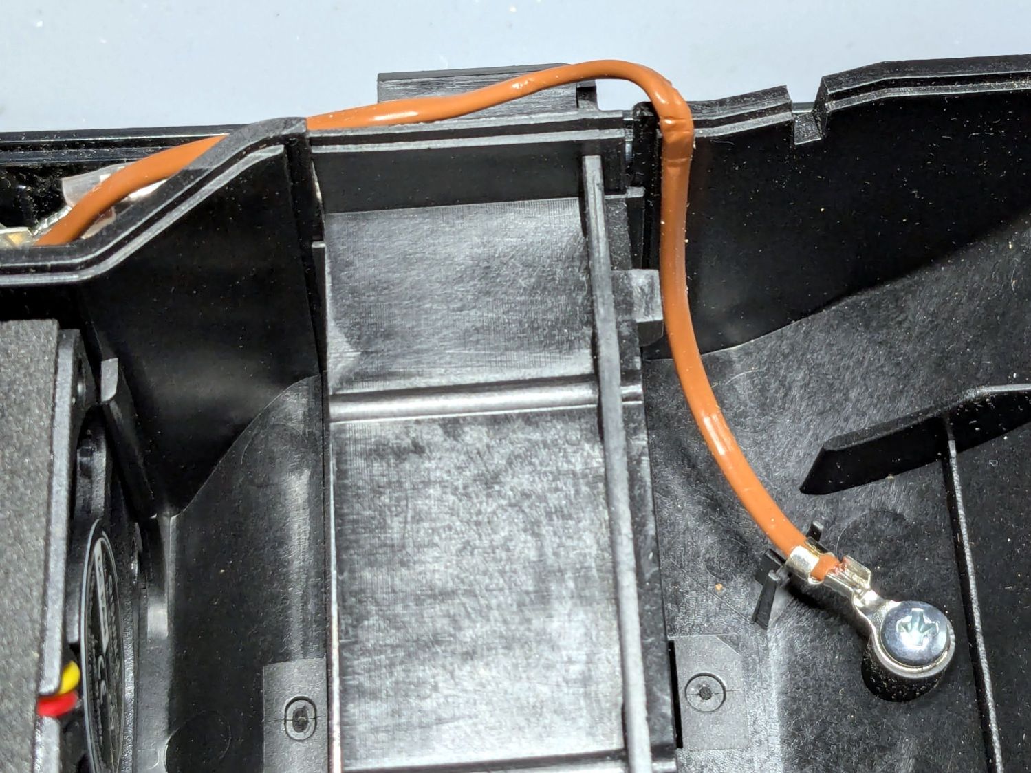
The brown thermocouple wire in the upper right didn’t start out in the notch intended to pass it out of the air flow downwind of the heater:
PolyDryer – crunched thermocouple wire
The wire is exceedingly stiff and requires some persuasion, but it will eventually stay in that slot.
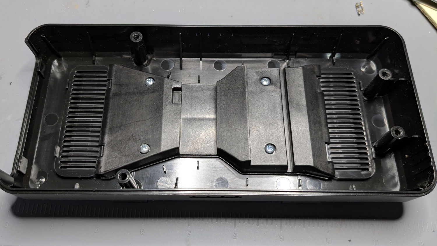
One of the PolyDryer modifications (which I can no longer find) suggested improving the vent openings, because the default slats block more than half of the surface area:
PolyDryer – molded vent slats
I chopped out all but three of the slats and stuffed an arch of aluminum window screen into each recess:
PolyDryer – vent screens installed
Admittedly, it looks a bit raggedy:
PolyDryer – vent screen – detail
As far as I can tell without actually measuring anything, the air flow has increased.
Now, to see how whether all that makes any difference.
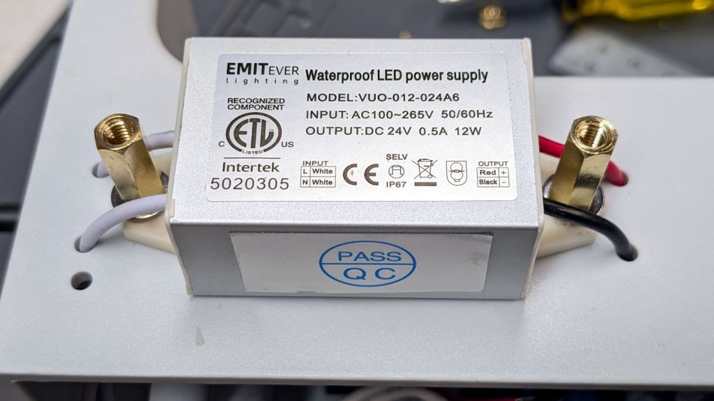
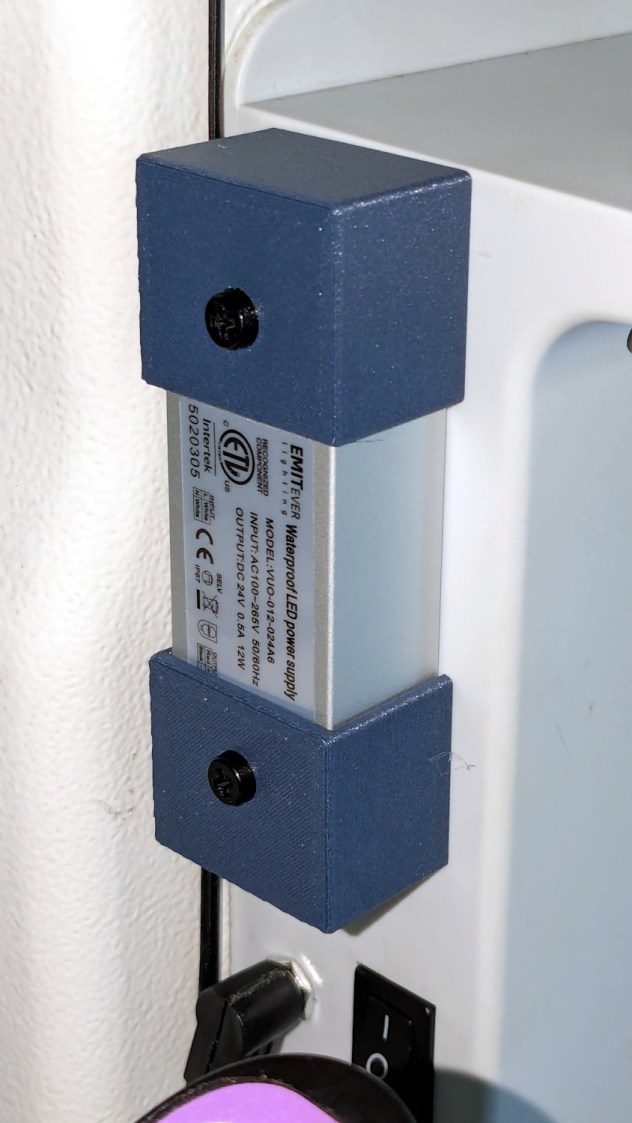
With the quilt off the HQ Sixteen, I could install the 24 V power supply for the Nose Ring Lights:
HQ Sixteen Nose Ring Lights – power supply installed
IMO, black nylon screws look spiffier than brass.
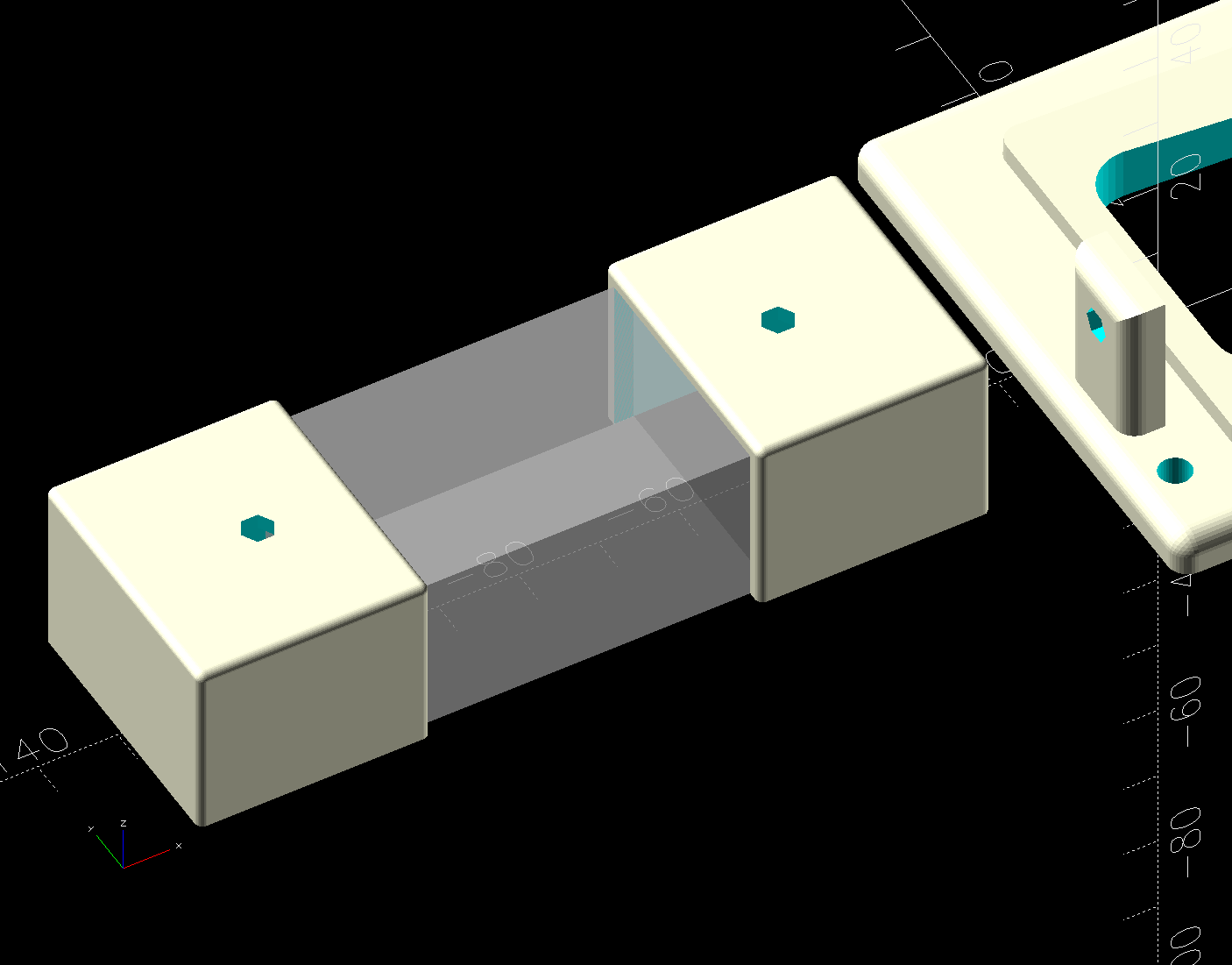
The solid model shows the covers have a 2 mm overlap with the power supply case to keep them lined up:
HQ Sixteen Nose Ring Lights – power supply cover – solid model
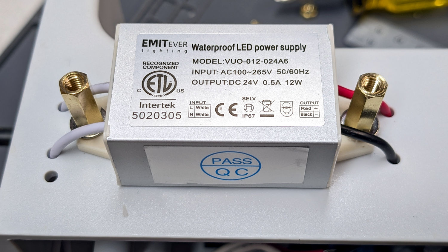
I managed to reuse three of the five holes from the previous 12 V power supply and drill only three more:
HQ Sixteen Nose Ring Lights – power supply detail
The tops of the power supply ears aren’t quite flat, giving the standoffs a slight tilt that the covers mostly drag back into alignment.
The M4 brass standoffs screw into holes tapped in the thick plastic, thus eliminating nuts inside the power pod:
HQ Sixteen Nose Ring Lights – power supply wiring
The yellow silicone tape wraps two pairs of Wago connectors that dramatically simplify electrical connections in anything with enough space for their chonky bodies.
In the unlikely event you need such things, the original post links the OpenSCAD source code.
With the power supply in place, I think I can put some LED strips under the arm of the machine to light up more of the quilt than the nose lights can reach. More pondering is in order.