The Smell of Molten Projects in the Morning

Ed Nisley's Blog: Shop notes, electronics, firmware, machinery, 3D printing, laser cuttery, and curiosities. Contents: 100% human thinking, 0% AI slop.

Category: Electronics Workbench

Electrical & Electronic gadgets

  • Whirlpool Clothes Dryer: Heater Examination

    Whirlpool Clothes Dryer: Heater Examination

    A correspondent (you know who you are: thanks!) pointed out the Thermal Cutoff can trip should the 240 V heater coil sag enough to contact the grounded steel air duct surrounding it. Think of a connection from the heater in the lower right corner of the wiring diagram to the neutral wire:

    Whirlpool dryer - wiring diagram - detail
    Whirlpool dryer – wiring diagram – detail

    If the short is close to the middle of the heating element, the right half the heater will remain active even when all of the normal thermostats cut off the left half. The two half-elements will see about their usual 120 V and won’t burn out, but the right half will continue to heat the air until the Thermal Cutoff trips at 350 °F.

    A short near either end of the heating element will subject that section to a higher voltage than usual and promptly burn it out, in which case the dryer will fail to heat due to the much lower power dissipated in the remaining section.

    So I took the dryer apart after a (successful!) washing day to see if that had happened.

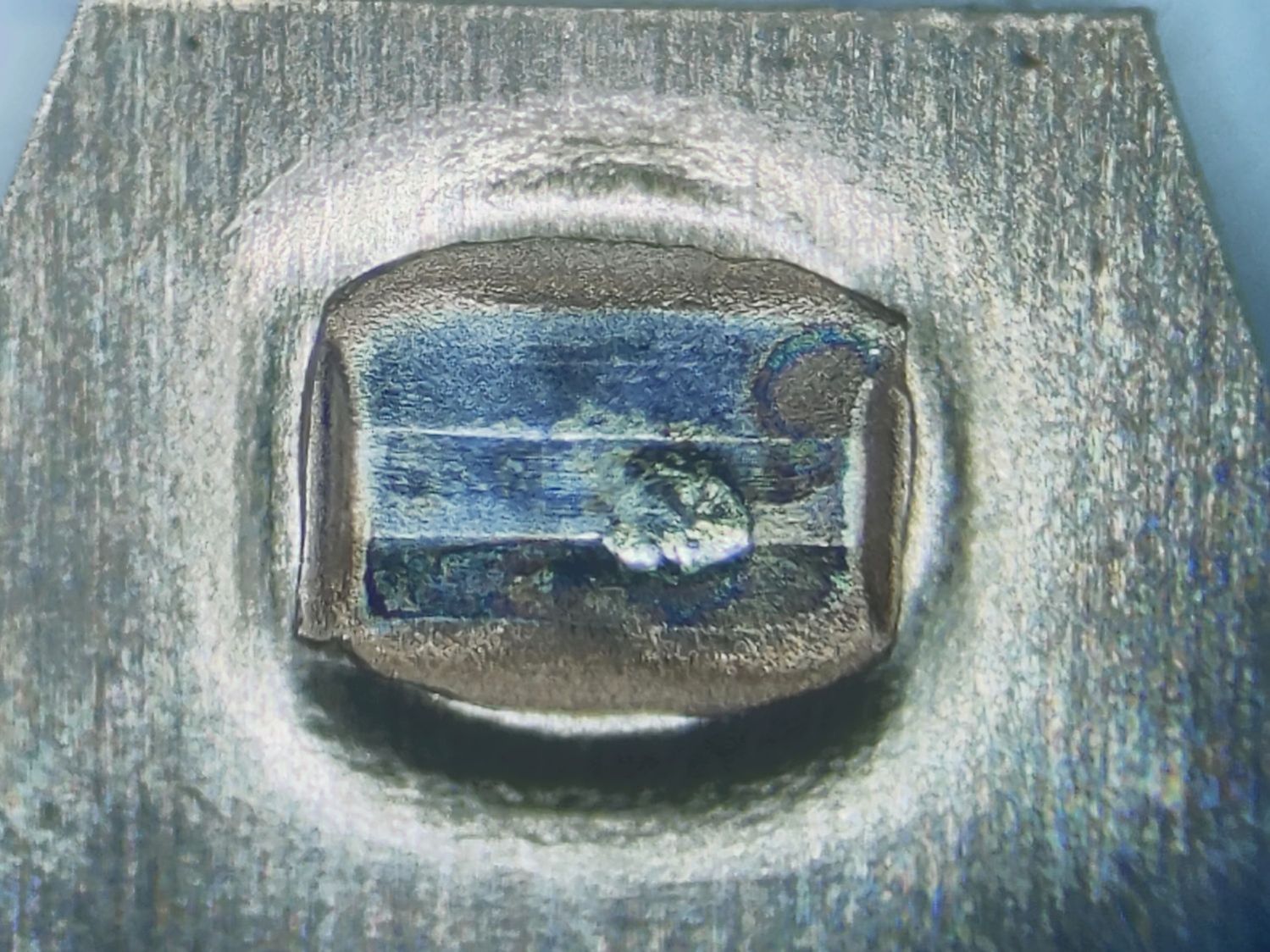
    A spring clip holds the top of the heater duct in place:

    Whirlpool Clothes Dryer - bulkhead parts - heater duct clip
    Whirlpool Clothes Dryer – bulkhead parts – heater duct clip

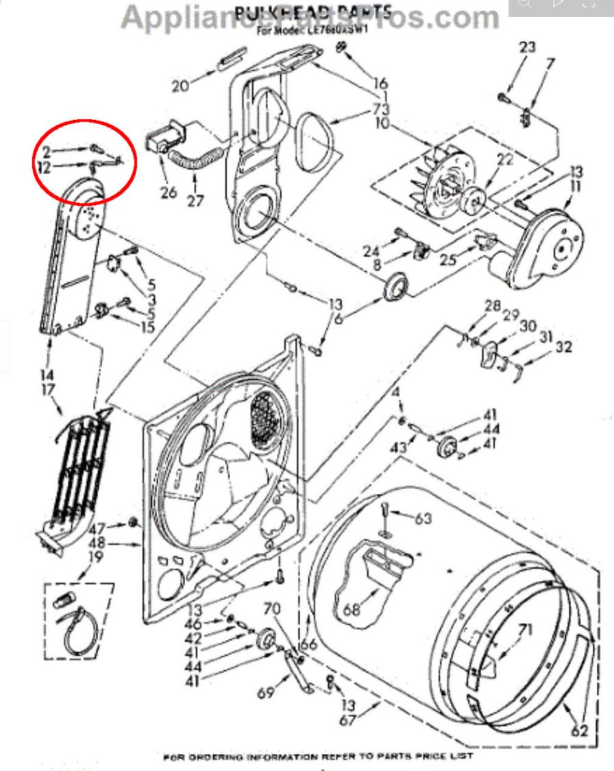
    AFAICT the clip cannot be disengaged from the duct in situ without removing the hex-head sheet metal screw holding it to the bulkhead, which requires inserting a 5/16 inch socket on the end of a 6 inch extension through a hole in the non-removable upper back cover. You (well, I) cannot see the screw from any position, so the process requires reaching up over the duct to position the socket by feel.

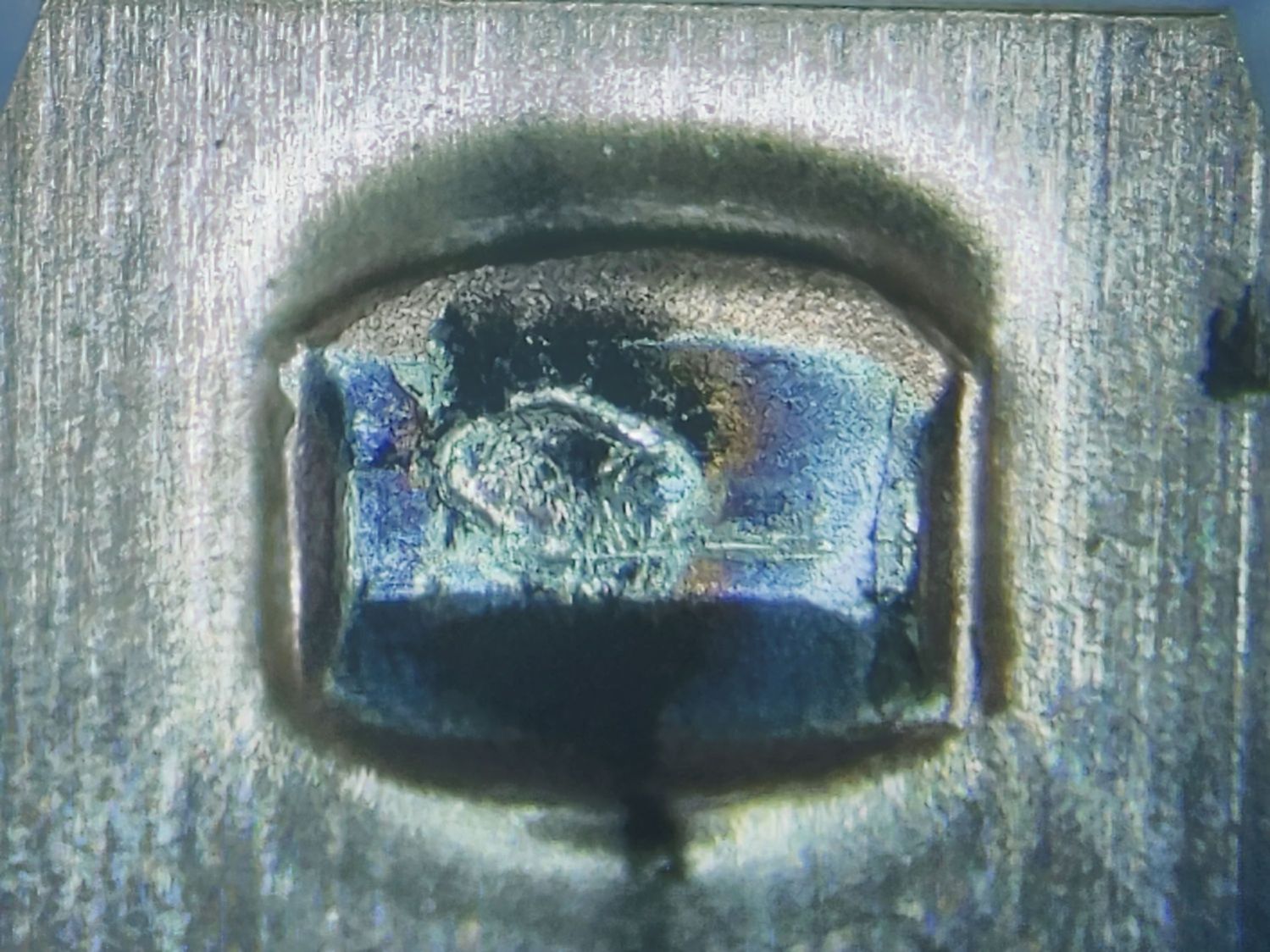
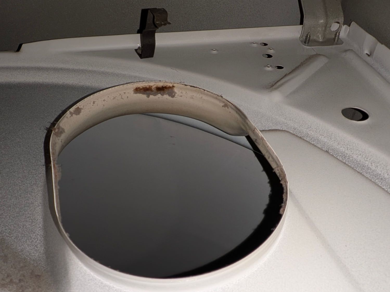
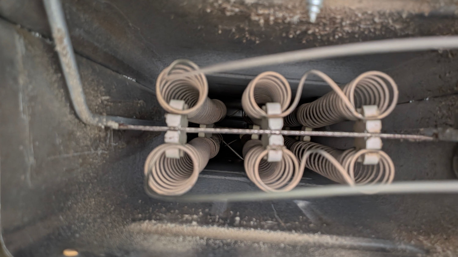
    This view looking up inside the dryer with the duct removed shows the clip on the bulkhead:

    Whirlpool Clothes Dryer - heater duct clip
    Whirlpool Clothes Dryer – heater duct clip

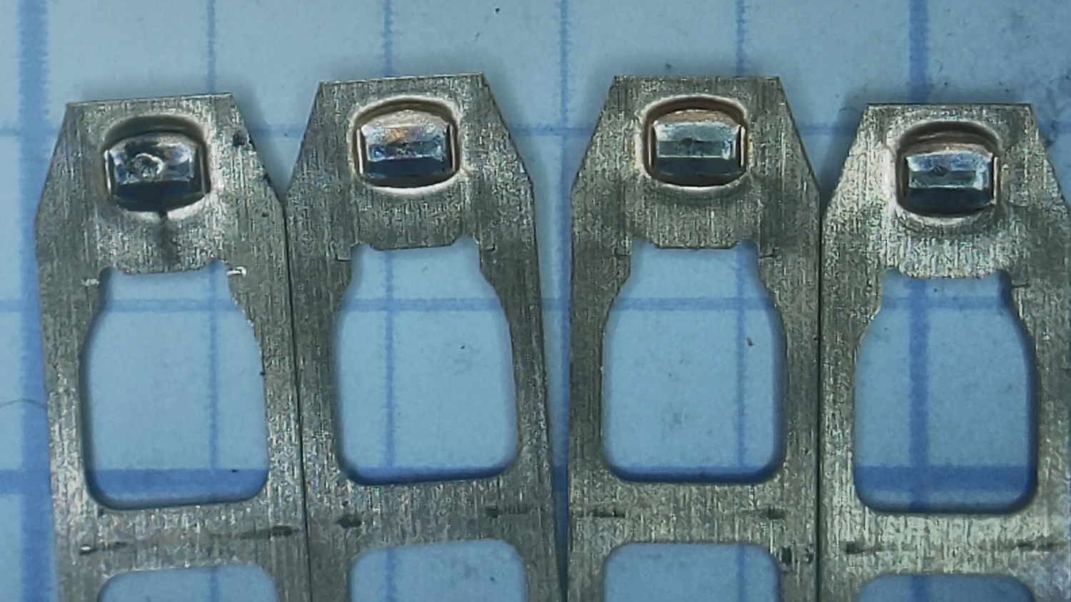
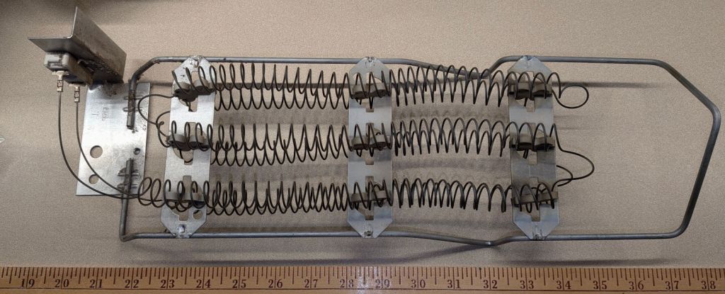
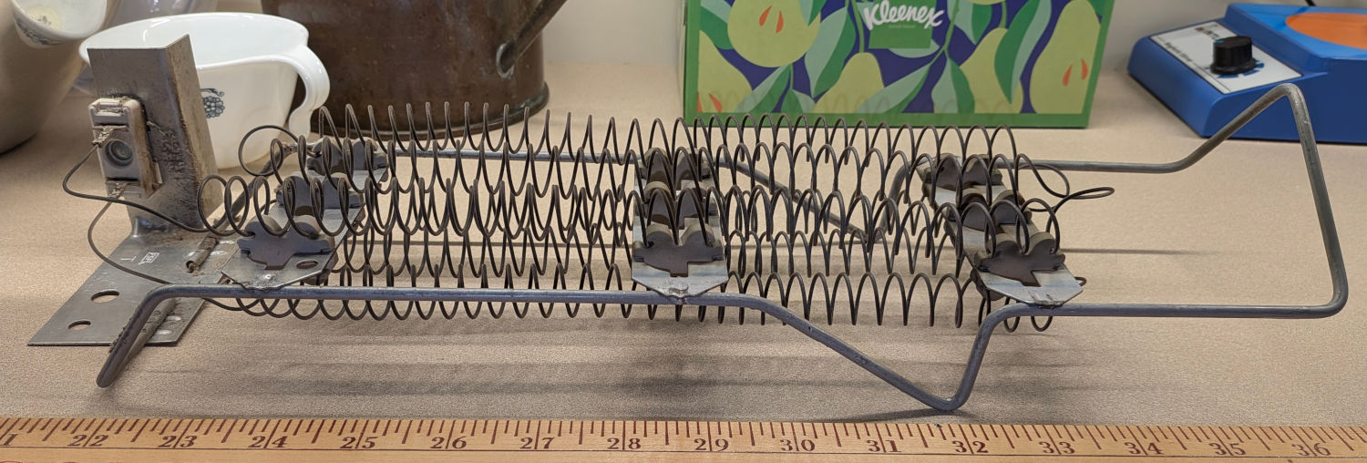
    The heating element looked to be in fine shape, with no sags or distortions:
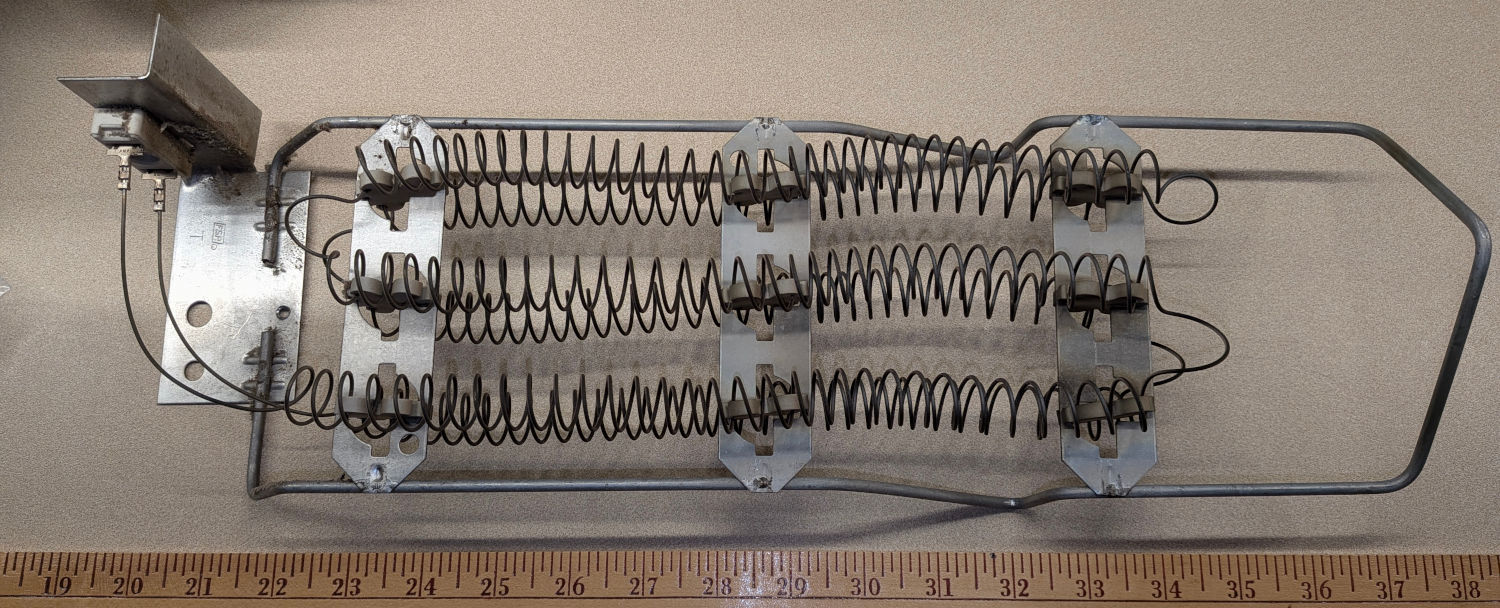
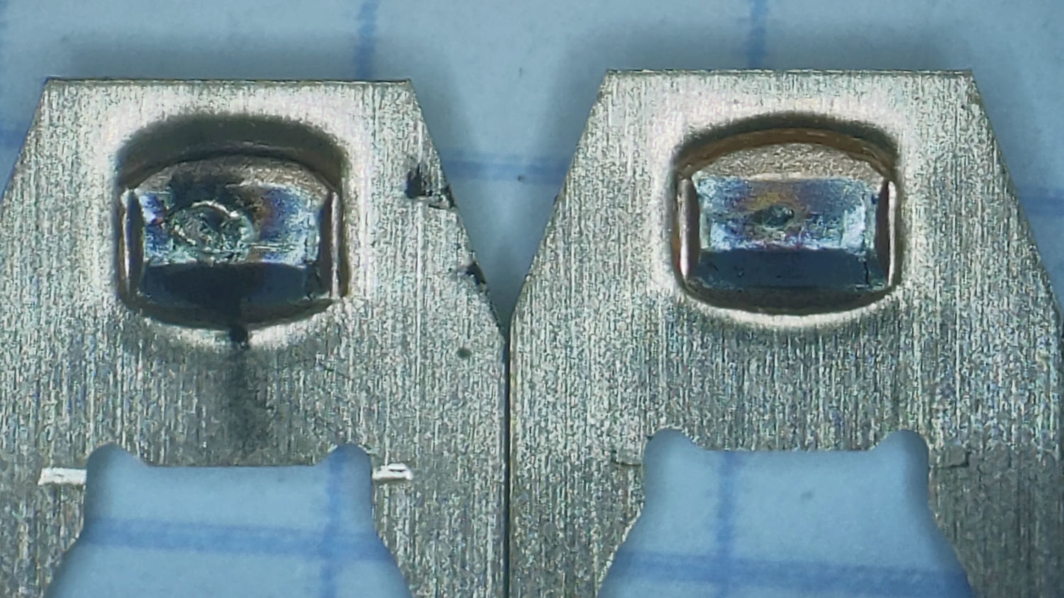
    Whirlpool Clothes Dryer - heater top view
    Whirlpool Clothes Dryer – heater top view

    A side view:

    Whirlpool Clothes Dryer - heater side view
    Whirlpool Clothes Dryer – heater side view

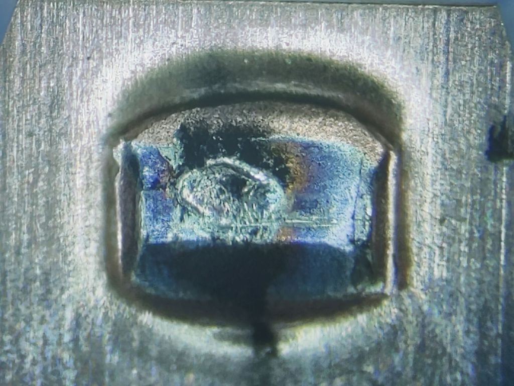
    Taking a picture of the duct’s interior is impossible, but an eyeballometric inspection shows no burns / scorches / pits from contact with the coils:

    Whirlpool Clothes Dryer - heater duct interior
    Whirlpool Clothes Dryer – heater duct interior

    So AFAICT the Thermal Cutoff tripped due to Inherent Defect, rather than an overly high temperature.

    Reinstalling the duct requires fitting the spring clip into its slot in the duct, maneuvering the duct onto its lower bulkhead brackets without dropping the clip, persuading the top of the duct with the clip into position, getting the screw into the clip and the hole, then aligning the socket with the screw. If I were doing this for a living, I would definitely charge you extra; newer dryers have an easily removable heating element for well and good reason.

    So the dryer is, once again, back together again and, once again, works as well as it ever did, with another set of thermostats / cutoffs in the box of dryer and washer parts against future need.

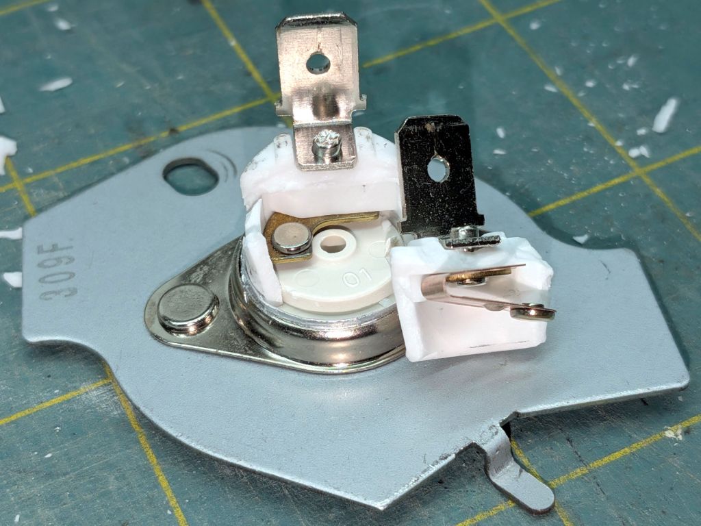
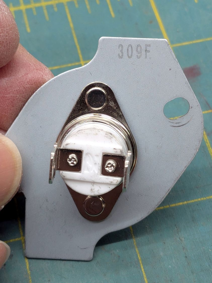
    For reference, the heater seems to be a WP4391960.

  • Whirlpool Clothes Dryer: Thermal Cutoff Trip

    Whirlpool Clothes Dryer: Thermal Cutoff Trip

    A bit less than a year after replacing all the thermal switches / cutoffs / thermostats in the Whirlpool clothes dryer, the Thermal Cutoff went open-circuit. It’s located at the top of the heater duct:

    Whirlpool dryer - heater duct top
    Whirlpool dryer – heater duct top

    The wiring diagram lists it as tripping at 350 °F and “NOT RESETTABLE”:

    Whirlpool dryer - wiring diagram - detail
    Whirlpool dryer – wiring diagram – detail

    Curiously, the replacement switch had only one mark:

    Whirlpool Clothes Dryer - thermal cutoff - marking
    Whirlpool Clothes Dryer – thermal cutoff – marking

    I find it difficult to believe anybody would build a thermal cutout at 309°F = 154 °C.

    Crushing it with a Vise-Grip reveals the interior:

    Whirlpool Clothes Dryer - thermal cutoff - disassembled
    Whirlpool Clothes Dryer – thermal cutoff – disassembled

    I don’t know what permanently opens the circuit in there, but it definitely happened. The contacts remain unblemished, so they were pressed firmly together until the end.

    With nothing to lose, I reinstalled the Thermal Cutoff I removed last year (*) and the dryer works fine again.

    It is possible lint accumulating in the filter bag I added to the exhaust vent restricted the airflow enough to overheat the cutoff, but the Operating Thermostat should keep the air around 155 °F and the Hi Limit thermostat should have tripped at 250 °F, long before the temperature reached 350°F.

    Another cutoff will arrive shortly and will remain in the Box o’ Dryer Parts against future need.

    (*) Which is why I keep the old parts around, because a dubious part on hand is much better than the new part I might not be able to get due to, oh, “supply chain issues”.

  • Kensington Expert Mouse Trackball: Switch Failure

    Kensington Expert Mouse Trackball: Switch Failure

    All of my Kensington Expert Mouse Trackballs have worked fine for the last several years, despite their previous history of scroll ring troubles, until the main button on the trackball at my left hand stopped responding to thumb pressure.

    You can tell that button has done a lot of clicking:

    Kensington Expert Mouse Trackball - worn button
    Kensington Expert Mouse Trackball – worn button

    The switch layout comes as no surprise:

    Kensington Expert Mouse Trackball - switch layout
    Kensington Expert Mouse Trackball – switch layout

    Those are Genuine Omron D2F-01 SPDT switches and the replacements are Genuine Anonymous D2F-01F. While I had the cover off, I replaced all four switches.

    Protip: The black cable on the right must go under the three wires between the PCBs. Arranged as shown, the scroll ring will drag on the cable.

    I dismantled the switches and put their Common bar under the microscope. I believe these contacts rest on the Normally Closed switch terminal, which is electrically inert:

    Kensington Expert Mouse Trackball - NC contacts
    Kensington Expert Mouse Trackball – NC contacts

    Three of them have about the same amount of wear:

    Kensington Expert Mouse Trackball - NC contact 2
    Kensington Expert Mouse Trackball – NC contact 2

    The leftmost one looks worse:

    Kensington Expert Mouse Trackball - NC contact 1
    Kensington Expert Mouse Trackball – NC contact 1

    Flipping them over (in the same order) exposes what I think are their Normally Open contacts responsible for all the button action:

    Kensington Expert Mouse Trackball - NO contacts
    Kensington Expert Mouse Trackball – NO contacts

    Again, the rightmost three look about the same and the contact on the left shows more wear, plus what looks like a soot streak:

    Kensington Expert Mouse Trackball - NO Contacts 1 2
    Kensington Expert Mouse Trackball – NO Contacts 1 2

    A closer look:

    Kensington Expert Mouse Trackball - NO Contact 1
    Kensington Expert Mouse Trackball – NO Contact 1

    These things operate at logic levels, so most of the damage surely comes from mechanical erosion and the soot is pulverized metal.

    While waiting for the switches to arrive, I deployed an Expert Mouse Trackball from a PC in the Basement Shop. The repaired unit went down there, so its new switches should survive longer even if they’re of mediocre quality.

  • Auto Parking Light LED Bulbs: FAIL

    Auto Parking Light LED Bulbs: FAIL

    After about eight years and a similar failure last year, this came as no surprise:

    White W5W Parking Light - failed chips
    White W5W Parking Light – failed chips

    It’s a W5W “parking light” in the same fixture as the melty halogen high-beam bulbs (used as daytime running lights at half power), so it gets toasted on those occasions when we drive somewhere.

    The adhesive holding the LED strip to the aluminum shell fossilized and came loose:

    White W5W Parking Light - failed adhesive
    White W5W Parking Light – failed adhesive

    Now that I know what to look for, I’d get LED bulbs with chips soldered directly to the PCB, although it’s not obvious what holds the PCB to the aluminum frame.

    I reinstalled the original incandescent bulbs.

  • LED Garage Light: Desk Lamp Upcycling

    LED Garage Light: Desk Lamp Upcycling

    One of the heatsink panels from the defunct LED garage light now casts a uniform warm-white glow on my desk:

    LED Garage Light - desk light
    LED Garage Light – desk light

    A PCB intended as a lithium battery charger serves as a constant-current supply:

    LED Garage Light - constant current driver
    LED Garage Light – constant current driver

    The three trimpots, from left to right:

    • Constant-voltage limit adjustment
    • Full-charge current setpoint (irrelevant here)
    • Constant-current limit adjustment

    The as-received trimpot settings will be wildly inappropriate for a nominal 10 W COB LED array, so:

    • Connect the output to about 10 Ω of power resistors
    • … with an ammeter in series
    • Connect the input to a 12 VDC / 1-ish A wall wart
    • Adjust the output voltage to 10 V
    • Adjust the output current to 900 mA

    As long as the voltage limit is over about 10 V, it will (likely) never matter, as the LED forward drop doesn’t vary much with temperature. Setting it to something sensible keeps it out of the way.

    The middle trimpot apparently sets a voltage for a comparator to light an LED when the battery current drops below that level as it reaches full charge.

    Although the regulator touts its high efficiency, it does run hot and a heatsink seemed in order:

    LED Garage Light - heatsink
    LED Garage Light – heatsink

    Stipulated: the fins run the wrong way and it’s sitting in the updraft from the main heatsink. It’s Good Enough™.

    The switch on the top comes from the collection of flashlight tailcap switches and controls the 12 V input power. It’s buried up to its button in a generous dollop of JB Kwik epoxy, which seemed the least awful way to get that done.

    The solid model looks about like you’d expect:

    LED Lamp Driver case - switch housing - show solid model
    LED Lamp Driver case – switch housing – show solid model

    The OpenSCAD code exports the (transparent) lid as an SVG so I can import it into LightBurn and laser-cut some thin acrylic. Two tape snippets hold the lid in place pending more power-on hours, after which I’ll apply a few dots of cyanoacrylate adhesive and call it done.

    The case builds in two pieces that glue together to avoid absurd support structures:

    LED Lamp Driver case - switch housing - build solid model
    LED Lamp Driver case – switch housing – build solid model

    A 3D printed adapter goes between the desk lamp arm and the lamp heatsink bolt:

    LED Lamp Driver case - arm adapter - solid model
    LED Lamp Driver case – arm adapter – solid model

    The OpenSCAD source code files for the case and adapter arm as a GitHub Gist:

    // LED Lamp arm adapter
    // Ed Nisley – KE4ZNU
    // 2026-03-18
    include <BOSL2/std.scad>
    Layout = "Adapter"; // [Show,Build,ArmClamp,SinkClamp,Adapter]
    /* [Hidden] */
    HoleWindage = 0.2;
    Protrusion = 0.01;
    Gap = 5.0;
    $fn=5*3*4;
    HoleOC = 45.0;
    ArmRad = 7.5;
    ArmWidth = 11.3;
    SinkOD = 11.5;
    SinkThick = 3.2;
    SinkOC = 20.0;
    ClampThick = 5.0; // outside sink, watch thinning due to hull()
    // Define things
    // Screw & bushings in lamp arm bracket
    // … over-long bushings to prevent coincident surfaces
    module ArmClamp() {
    BushingThick = 1.5;
    BushingOD = 9.0;
    union() {
    ycyl(ArmWidth,d=4.0 + HoleWindage); // central M4 screw
    for (j=[-1,1]) {
    back(j*(ArmWidth – BushingThick + Protrusion)/2)
    ycyl(BushingThick + Protrusion,d=BushingOD);
    back(j*(ArmWidth + 10)/2)
    cuboid([2*ArmRad,10,2*ArmRad]);
    }
    }
    }
    module SinkClamp() {
    union() {
    ycyl(2*SinkOC,d=6.0 + HoleWindage); // central M6 screw
    for (j=[-1,1])
    back(j*SinkOC/2) {
    ycyl(SinkThick + Protrusion,d=SinkOD);
    cuboid([SinkOD,SinkThick + Protrusion,2*SinkOD]);
    }
    }
    }
    module Adapter() {
    difference() {
    hull() {
    right(HoleOC)
    ycyl(ArmWidth,r=ArmRad);
    ycyl(SinkOC + SinkThick + 2*ClampThick,d=SinkOD);
    }
    right(HoleOC)
    ArmClamp();
    SinkClamp();
    }
    }
    // Build it
    if (Layout == "ArmClamp")
    ArmClamp();
    if (Layout == "SinkClamp")
    SinkClamp();
    if (Layout == "Adapter")
    Adapter();
    if (Layout == "Build")
    up(SinkOD/2)
    yrot(-atan((ArmRad – SinkOD/2)/HoleOC))
    Adapter();
    // LED Constant-current driver case
    // Ed Nisley – KE4ZNU
    // 2026-03-15
    include <BOSL2/std.scad>
    Layout = "Show"; // [Show,Build,Case,Lid,LidSVG,Switch]
    /* [Hidden] */
    ThreadThick = 0.2;
    HoleWindage = 0.2;
    Protrusion = 0.01;
    Gap = 5.0;
    WallThick = 1.8;
    TapeThick = 1.5;
    DriverOA = [48.5,13.5 + TapeThick,23.5]; // PCB forward Y, pots along top to rear
    SinkOA = [31.5,12.0,15.5]; // fins forward
    SinkOffset = [(DriverOA.x – SinkOA.x)/2,0,2.0]; // from lower left front corner of PCB
    AdjPots = [14,24,34]; // screwdriver adjust offsets
    AdjOD = 3.0; // … access hole dia
    CaseOA = DriverOA + [2*WallThick,2*WallThick,2*WallThick];
    echo(CaseOA=CaseOA);
    LidOA = [CaseOA.x – WallThick,CaseOA.z – WallThick,1.0];
    Cables = [8.0,3.0 + WallThick/2,LidOA.z];
    SwitchWireOC = DriverOA.x – 6.0;
    SwitchCapBase = [DriverOA.x + WallThick,DriverOA.y + WallThick];
    SwitchCapTop = [DriverOA.x,12.0];
    SwitchCavity = [25.0,10.5,5.5];
    // Define things
    module Lid() {
    difference() {
    cuboid(LidOA,anchor=BOTTOM+FWD+LEFT);
    for (i = AdjPots)
    translate([i,LidOA.y – AdjOD/2 – WallThick/2,-Protrusion])
    cyl(LidOA.z + 2*Protrusion,d=AdjOD,anchor=BOTTOM,$fn=8,spin=180/8);
    translate([LidOA.x/2,-Protrusion,-Protrusion])
    cuboid(Cables + [0,Protrusion,2*Protrusion],rounding=1.0,edges=[BACK+LEFT,BACK+RIGHT],anchor=BOTTOM+FWD);
    }
    }
    module SwitchBox() {
    difference() {
    prismoid(SwitchCapBase,SwitchCapTop,SwitchCavity.z,anchor=BOTTOM);
    down(Protrusion)
    cuboid(SwitchCavity + [0,0,2*Protrusion],anchor=BOTTOM);
    hull()
    for (i=[-1,1])
    right(i*SwitchWireOC/2)
    zcyl(CaseOA.z,d=3.0,$fn=8,spin=180/8);
    }
    }
    module Case() {
    difference() {
    cuboid(CaseOA,chamfer=WallThick/2,anchor=BOTTOM+FWD+LEFT);
    translate([WallThick,WallThick + Protrusion,WallThick])
    cuboid(DriverOA + [0,WallThick + Protrusion,0],anchor=BOTTOM+FWD+LEFT);
    translate(SinkOffset + [WallThick,WallThick + 2*Protrusion,WallThick])
    cuboid(SinkOA,anchor=BOTTOM+BACK+LEFT);
    for (i=[-1,1])
    translate([i*SwitchWireOC/2 + CaseOA.x/2,CaseOA.y/2,CaseOA.z/2])
    zcyl(CaseOA.z,d=2.0,anchor=BOTTOM,$fn=8,spin=180/8);
    translate([WallThick/2,(CaseOA.y + LidOA.z),WallThick/2])
    xrot(90)
    scale([1,1,2])
    Lid();
    }
    }
    // Build it
    if (Layout == "Switch")
    SwitchBox();
    if (Layout == "Case")
    Case();
    if (Layout == "Lid")
    Lid();
    if (Layout == "LidSVG")
    projection(cut=true)
    Lid();
    if (Layout == "Show") {
    Case();
    translate(SinkOffset + [WallThick,WallThick + 2*Protrusion,WallThick])
    color("Gray",0.7)
    cuboid(SinkOA,anchor=BOTTOM+BACK+LEFT);
    translate([CaseOA.x/2,CaseOA.y/2,CaseOA.z])
    SwitchBox();
    translate([WallThick/2,CaseOA.y,WallThick/2])
    xrot(90)
    color("Gray",0.7)
    Lid();
    }
    if (Layout == "Build") {
    fwd(Gap)
    xrot(90)
    Case();
    translate([CaseOA.x/2,(Gap + CaseOA.y/2),0])
    SwitchBox();
    }
  • Magnetic Stirrer: Interior

    Magnetic Stirrer: Interior

    Of late, the magnetic stirrer mixing my morning cocoa occasionally doesn’t start spinning when I turn it on, which calls for some investigation.

    Removing the four obvious screws concealed under the rubber feet and prying off bottom cover reveals the trivial innards:

    Magnetic stirrer - interior
    Magnetic stirrer – interior

    The speed adjustment pot holds the little circuit board in place, with the green LED setting its jaunty angle.

    The motor spins a pair of neodymium magnets:

    Magnetic stirrer - magnet holder
    Magnetic stirrer – magnet holder

    I expected a gearbox instead of the direct drive setup.

    Perhaps those whirling neodymium magnets have been slowly demagnetizing the motor’s internal (alnico?) magnets.

    The motor brushes seem to be a pair of stiff wires, rather than carbon blocks, contacting the commutator, the wear from which may account for motor’s decreasing startup enthusiasm. Even though I didn’t expect a BLDC motor, this one may have been overly cheapnified.

    Perhaps kickstarting the motor with the steel fork I use to fish the stirrer magnet out of the mug will get the thing going.

  • LED Garage Light: Autopsy

    LED Garage Light: Autopsy

    The hidden part of all three LED arrays in the dead garage light looked like this:

    LED Garage Light - inadequate heatsink compound
    LED Garage Light – inadequate heatsink compound

    Although the compound was still gooey, there wasn’t nearly enough of it. The few tendrils on the heatsink suggest the LED array had bowed upward, pulled away from the cast aluminum, and eliminated any direct conduction.

    A bit of probing showed each LED array had 16 series groups of 4 parallel LEDS, with one group in each array failed open. That group was toward the end away from the inadequate heatsink compound: the LEDs died from heatstroke brought on by neglect.

    The Drawer o’ LED Arrays disgorged a bag of surplus LEDs labeled “10 W 9-12 V 750 mA”:

    LED Garage Light - epoxy replacement
    LED Garage Light – epoxy replacement

    It’s sitting on a generous blob of steel-filled JB Kwik epoxy that should do a great job of conducting heat. A bag of cheap constant-current supplies is on order.

    Amazon has similar “10 W 9-12 V 350-450 mA” arrays.

    Try as I might, I can’t get 10 W from those numbers, but I’ve never understood advertising math.