Ed Nisley's Blog: Shop notes, electronics, firmware, machinery, 3D printing, laser cuttery, and curiosities. Contents: 100% human thinking, 0% AI slop.
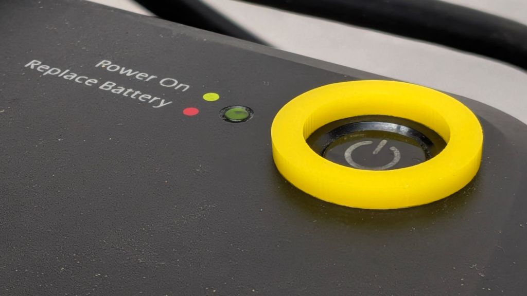
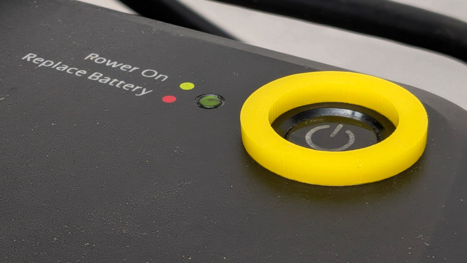
It turns out that dragging a USB cable across the top of the UPS for the PC (about to be) running the Sherline mill was enough to flip its flush-mounted hairtrigger power switch. Although I can’t recess the switch, adding a mollyguard should help:
Mollyguard – UPS power switch
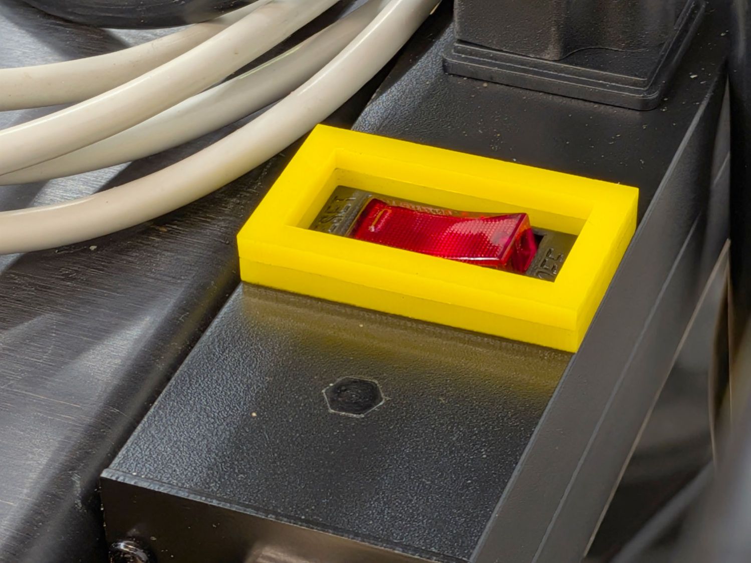
The power switches on the new outlet strips also seem unduly sensitive and a preemptive strike seemed in order:
Mollyguard – outlet strip switch
Two layers of 3 mm acrylic just barely clear the switch, but should prevent casual trips. AFAICT, the little hexagonal shape fills the hole for an indicator LED this strip doesn’t have.
The Samsung dishwasher (model DW80K7050US/AA 03) that Came With The House fails immediately after entering the Dry part of the cycle: a relay in the control PCB under the door goes doink, all the LEDS go off then on again, the countdown timer stops changing, and that repeats as long as you like.
After considerable listening & pondering, I decided one event early in the Dry cycle involved starting a fan to vent the steam out of the interior. The wiring diagram shows the fan has a Fault wire: perhaps the fan has failed.
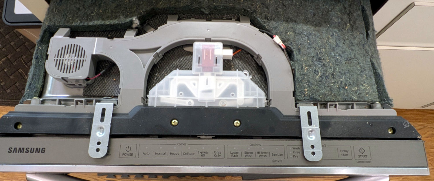
The maintenance manual shows different fans in three different places, although the control board has a connector for only one. By process of elimination, I found the fan atop the cabinet:
Samsung dishwasher – top view
The cable from the fan in the vented compartment on the left burrows under the gray duct, around its back side, and plugs into the small white connector on the right. You must ease the cable from a row of hooks guiding it around the back of the duct, which requires slightly lifting the duct.
Unhook the two metal straps, remove four screws from the black vent, and lift it off the top to reveal the duct outlet pores:
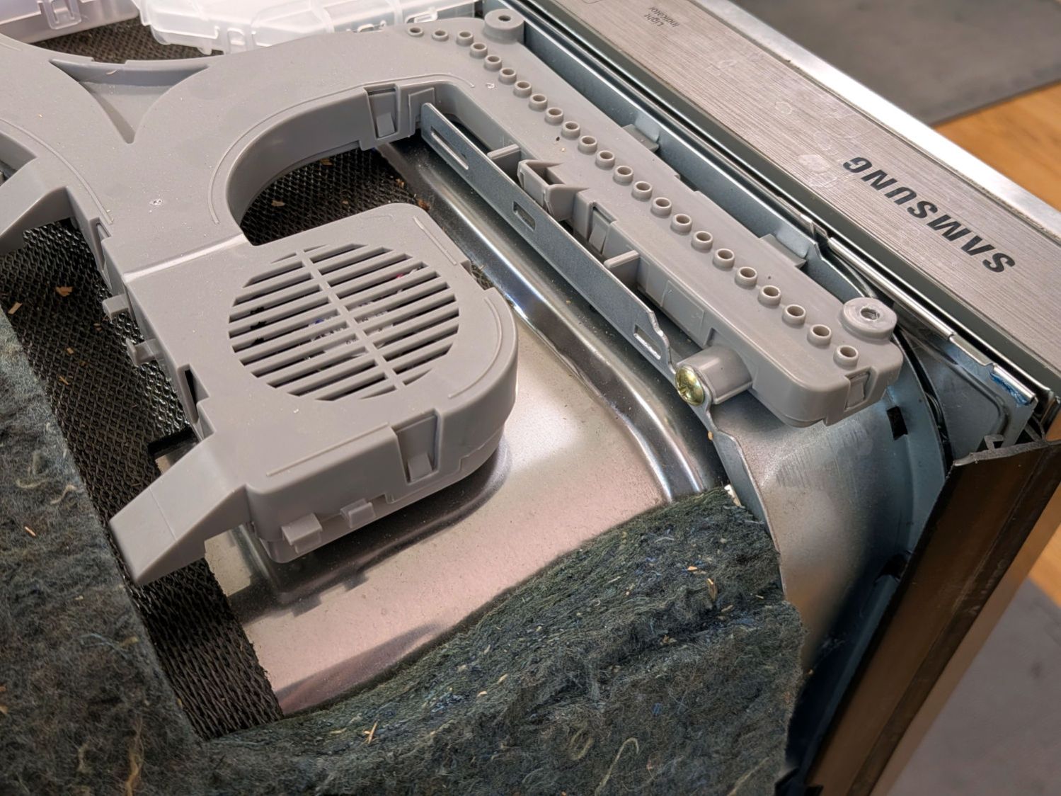
Samsung dishwasher – fan duct – overview
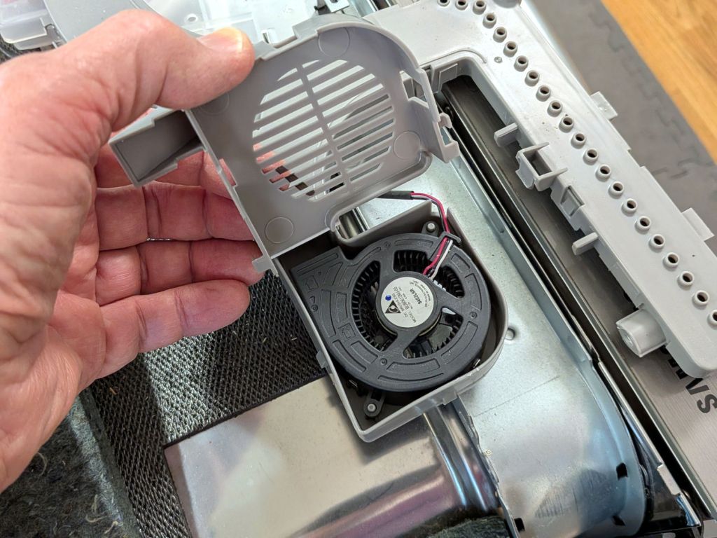
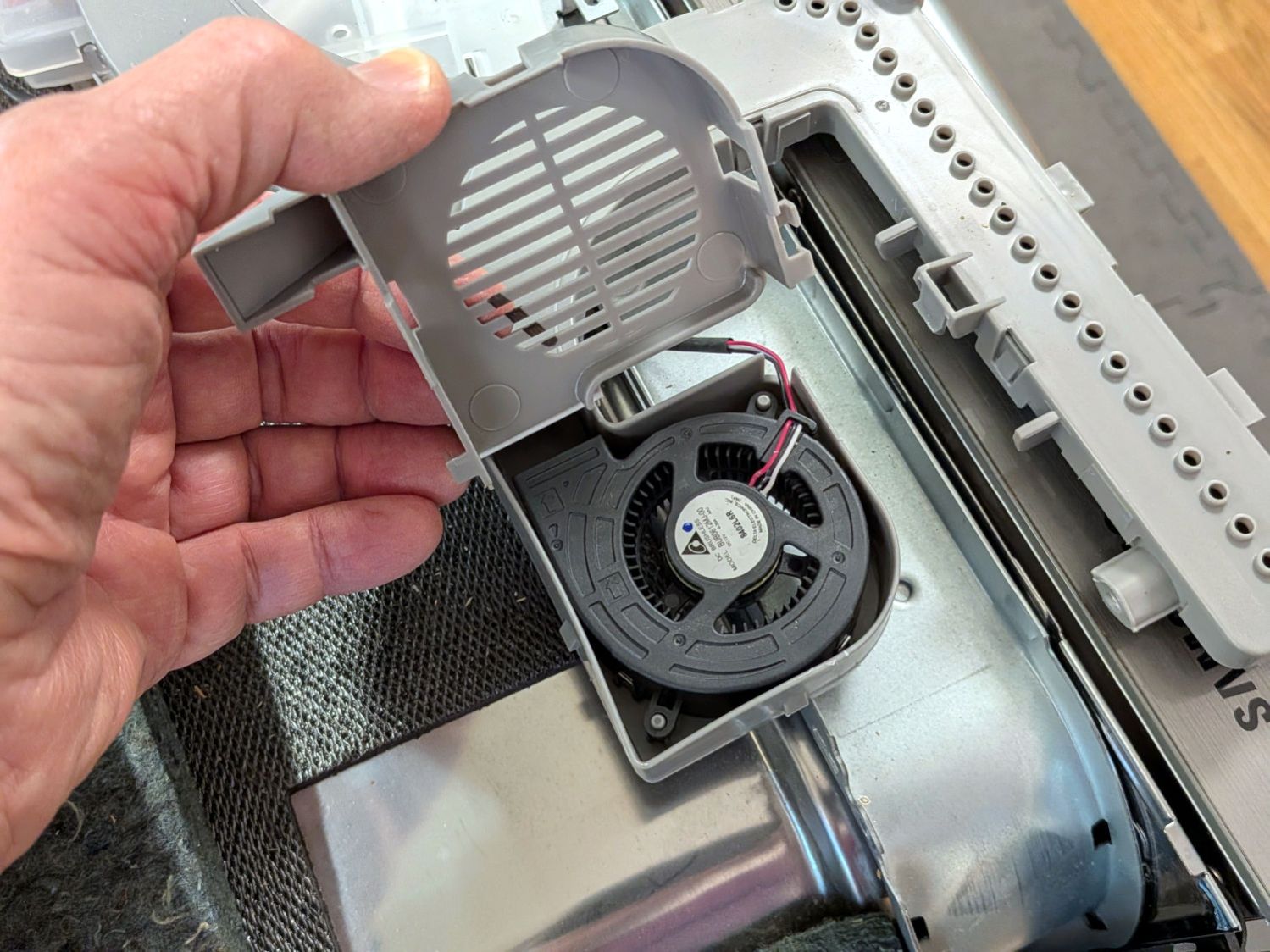
Remove four more screws, lift the fan duct assembly just a little bit, and pry open three latches around the fan compartment with a consumer electronics case-cracking tool:
Samsung dishwasher – fan housing
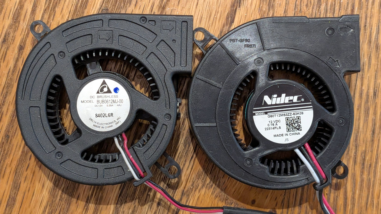
The new fan (on the right) looks very much like the OEM fan (on the left), even though it’s the $15 version rather than the $150 version you might buy from similar randomly named sellers if you were so inclined:
Samsung dishwasher – OEM vs new fan
Detach the old fan & its cable, drop the new fan in place, snake its cable, plug its plug, and install All The Things in reverse order.
Unfortunately, after shoving the dishwasher back into its cubby, the new fan didn’t change the failure at all.
I hitched the old fan up to the bench supply and it spun just like it should. Wiring the Fault wire to a 5 V supply through a resistor shows it’s the usual tachometer signal pulsing as the rotor spins.
Which means the next step requires more pondering and PCB probing. The failure is too consistent to be a Heisenbug, but maybe something shook loose in there.
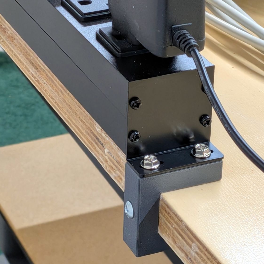
A spate of tidying-up led to mounting an outlet strip along the back of a bench:
Outlet Bench Mount – installed
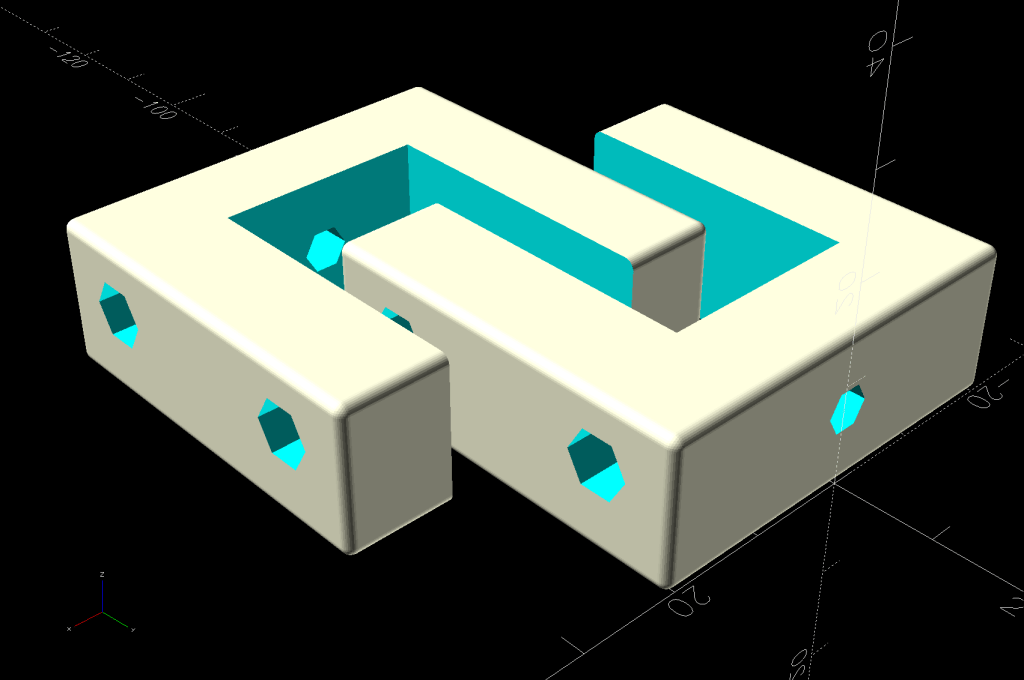
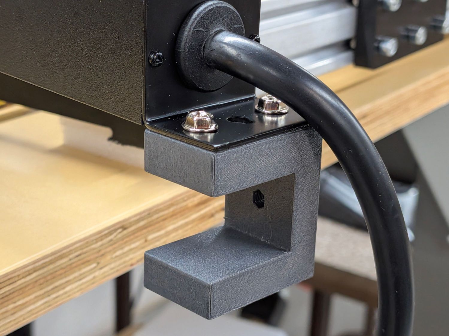
Rather than drill holes into the top of the bench for those screws, they fit into M4 brass inserts heat-staked into the brackets:
Outlet Bench Mount – show view
The holes for those inserts aren’t centered side-to-side on the brackets, because the screw holes aren’t centered on the bent-steel angles forming the outlet strip endplates.
The bottom arm on the brackets probably isn’t necessary, but they kept the outlet strip from crawling away while I match-drilled two holes for the screws into the side of the benchtop.
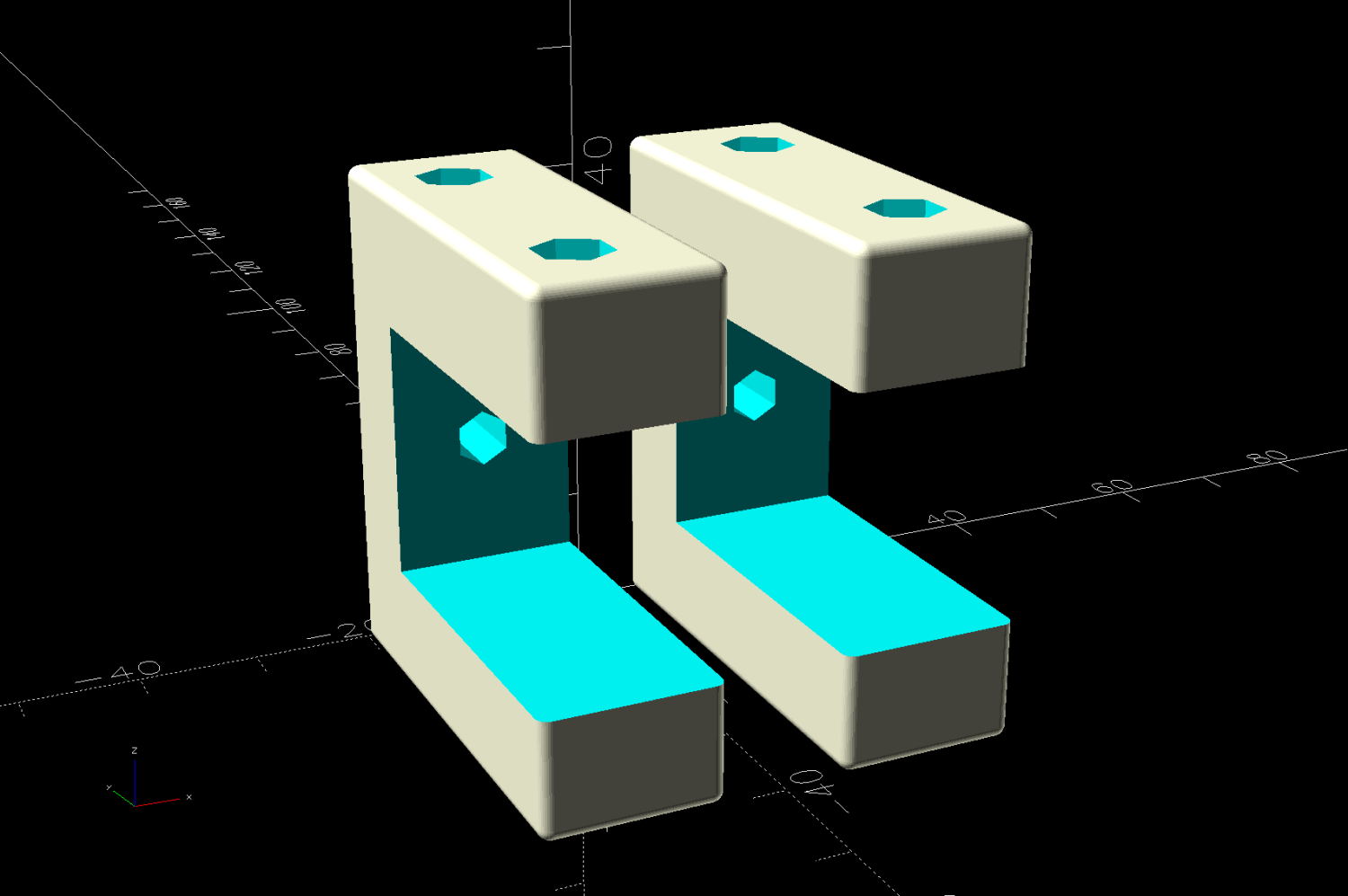
For obvious reasons, the brackets print on their sides:
Outlet Bench Mount – build view
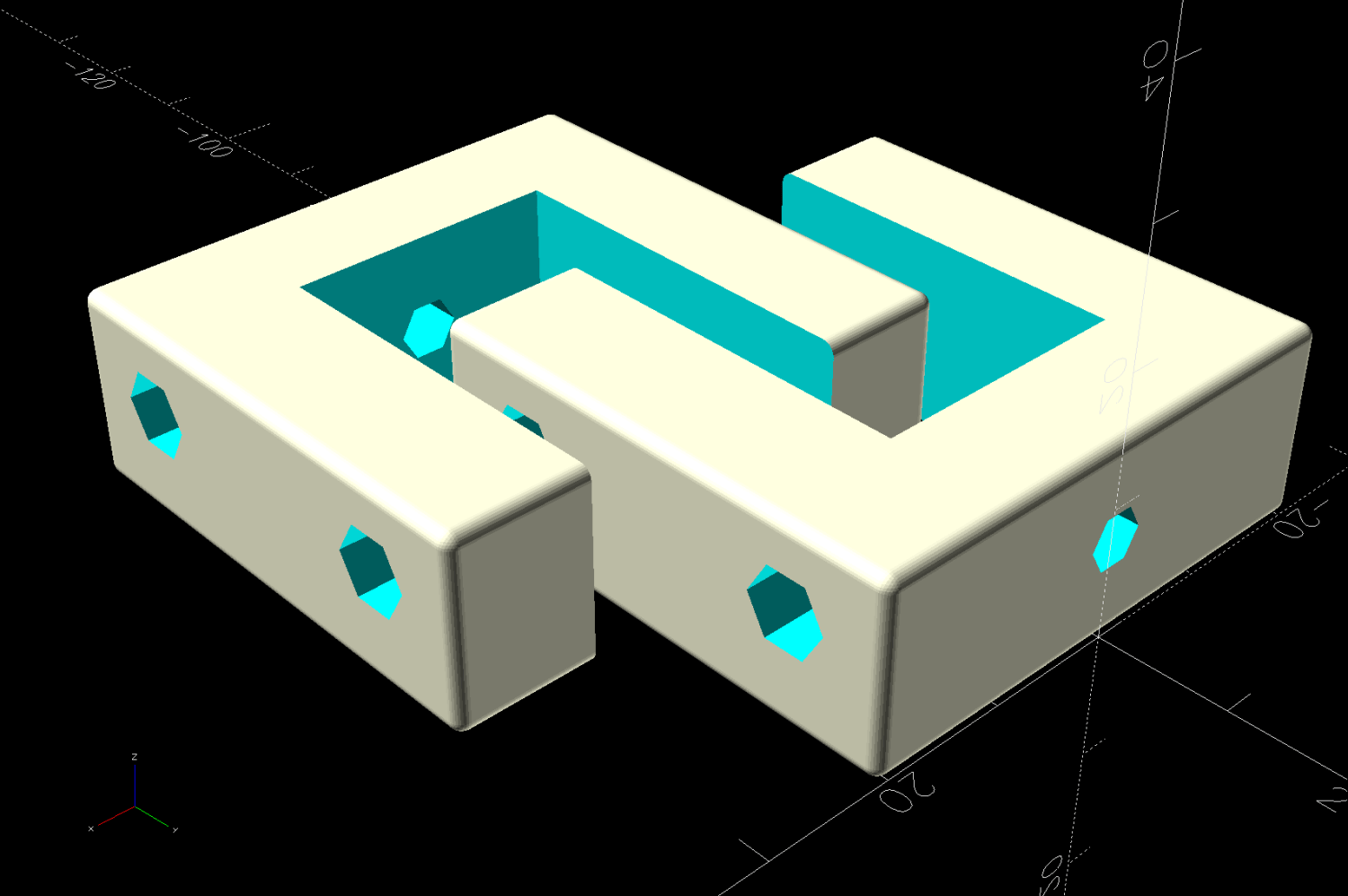
Another outlet strip from a different manufacturer is, of course, different, but changing three parameters in the OpenSCAD program summons a different bracket from the vasty digital deep:
Outlet Bench Mount – different brand
Parametric modeling and a 3D printer are exactly the right hammers for the job …
This file contains hidden or bidirectional Unicode text that may be interpreted or compiled differently than what appears below. To review, open the file in an editor that reveals hidden Unicode characters.
Learn more about bidirectional Unicode characters
Before measuring a wire resistance in the laser cutter, I checked the resistance of the two test leads on the Aneng AN8009 meter (“Check your zero!”) to show an unsteady reading around dozen ohms.
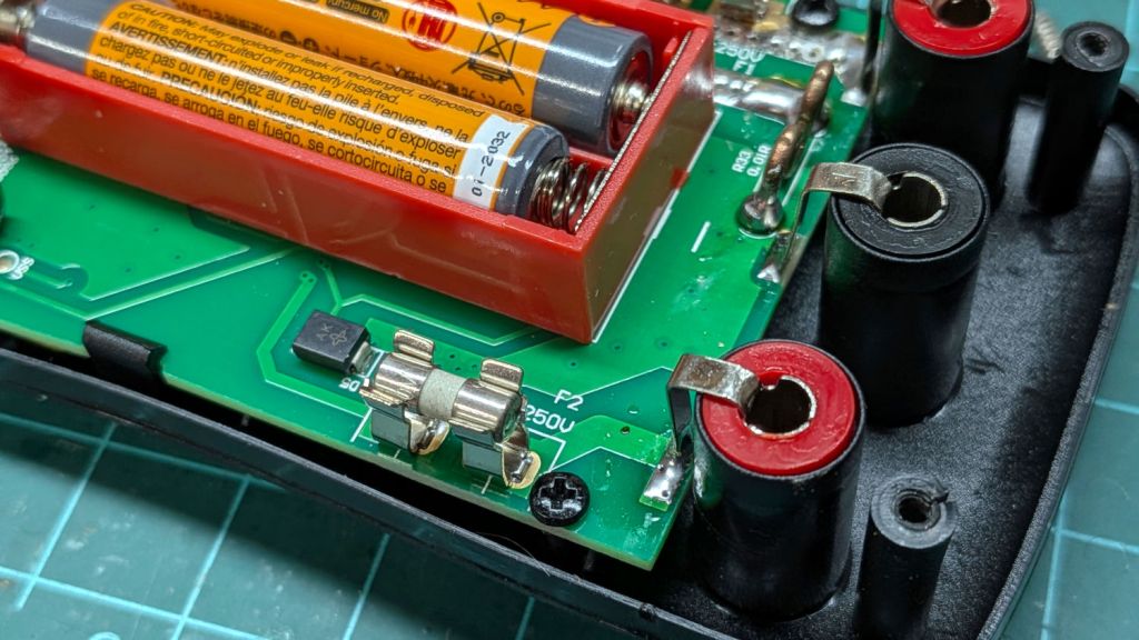
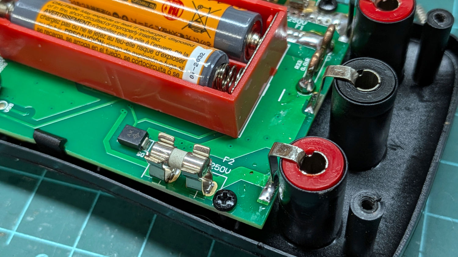
Poking around inside showed the internal fuse apparently making poor contact with its holder, as poking it changed the random values:
Aneng 8009 low-current fuse
Two tiny drops of Caig DeoxIT stabilized the reading around 1 Ω across several different combinations of test probes, so I declared victory. There is surely an offset calibration buried in the firmware, but it’s no longer a trimpot available to service technicians.
The ceramic fuse has an internal resistance of about an ohm, but swapping it for a replacement fuse with 0.2 Ω resistance didn’t materially change the results. It’s worth noting those glass fuses are slightly longer than they should be, surely due to their leads, and required slightly bending the fuseholder clips.
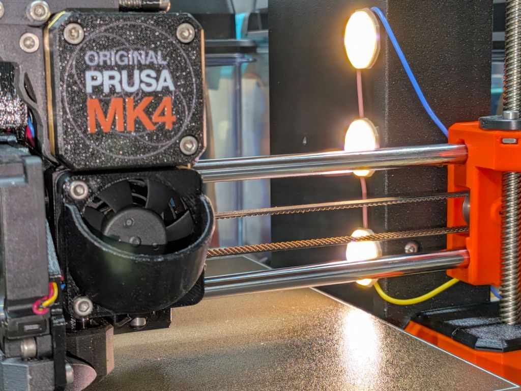
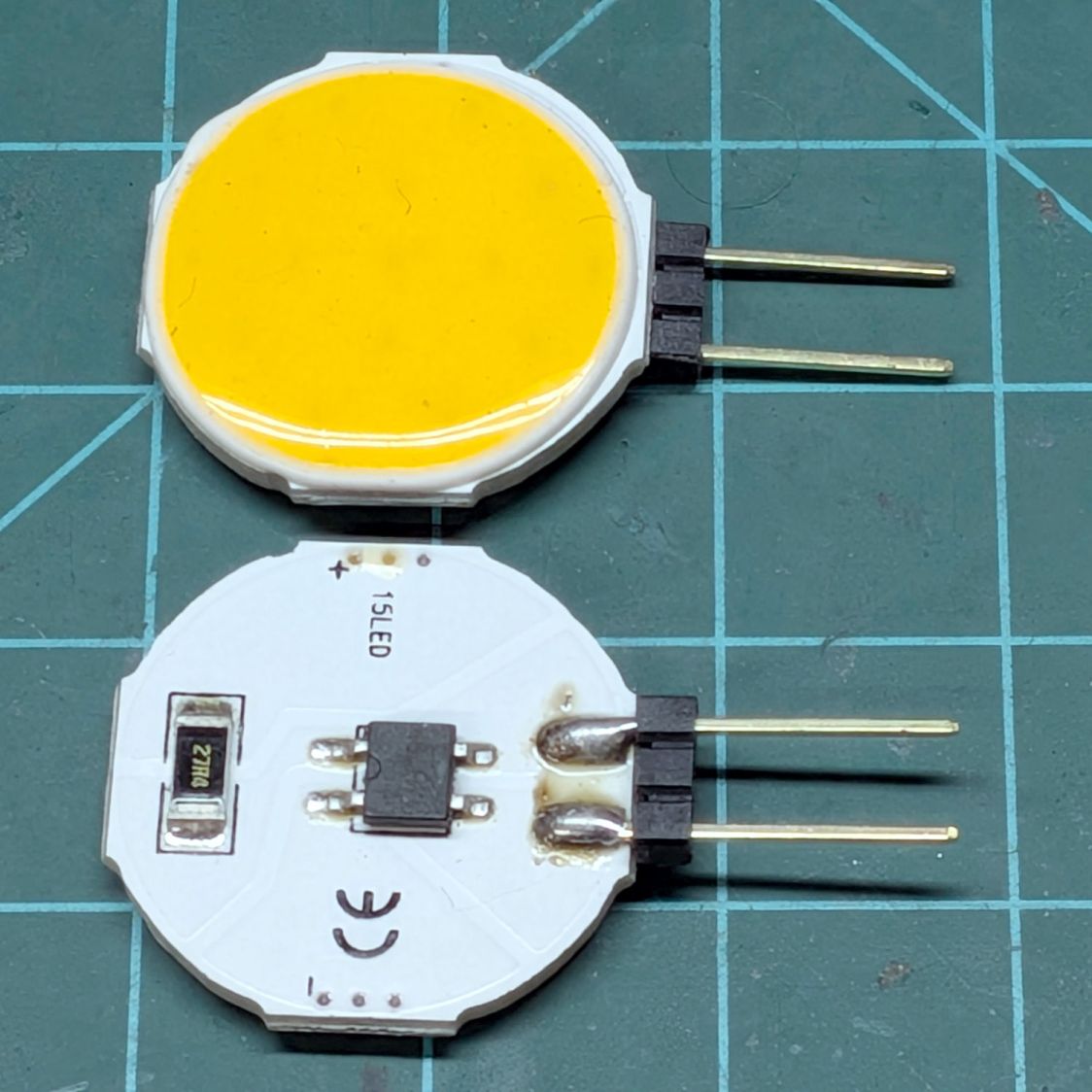
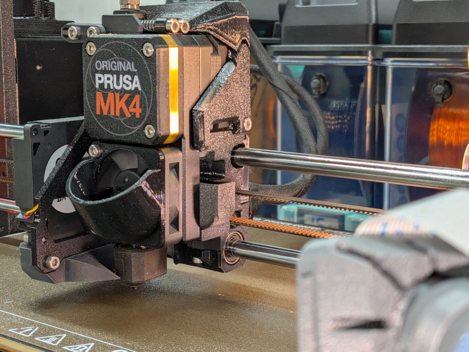
There’s also not much room for a lighting fixture on the printer where it must mount, so I modified a trio of nominally 12 V / 4 W COB LED panels:
Prusa MK4 – Extruder sidelight – COB LEDs
Their “4 W” rating seems aspirational, at best, as a 12 VDC supply pushes only 75 mA through the panel, so they tick along at 900 mW. If you expect cheap eBay / Amazon components to live up to their specs, dream on.
The modifications:
Unsolder the pins
Crunch off the surprisingly precise 27.4 Ω SMD resistor
Clean up the rubble
Wire the panels directly in series, ignoring their bridge rectifiers
The 15 LEDs on each panel are arranged in five parallel chains of three LEDs for a total forward drop of 8.3 V, so putting three panels in series works with the MK4’s 24 V power supply.
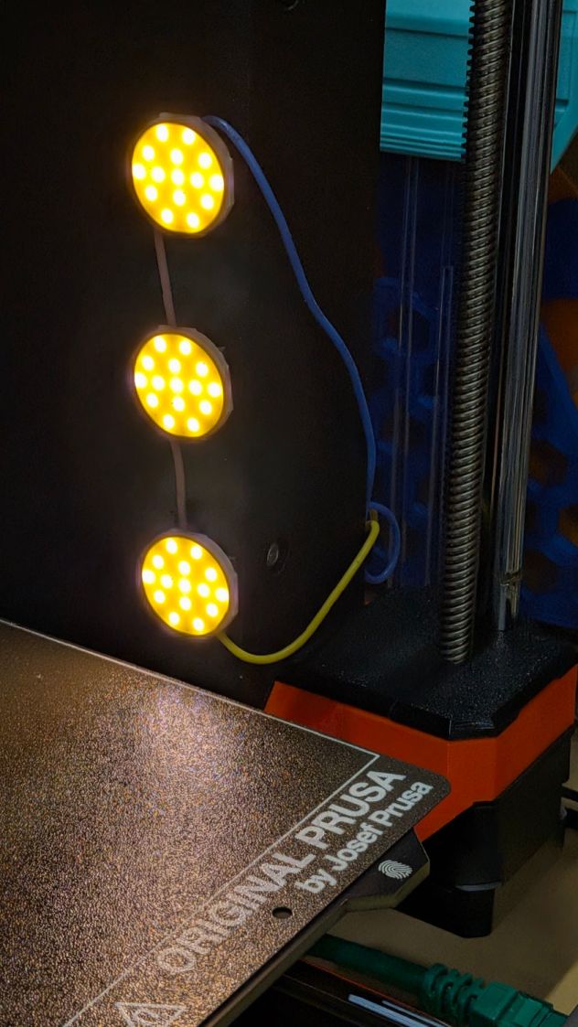
Stick them onto the MK4 power supply case with foam tape and wire them directly to the 24 V terminals:
Prusa MK4 – Extruder sidelight – installed
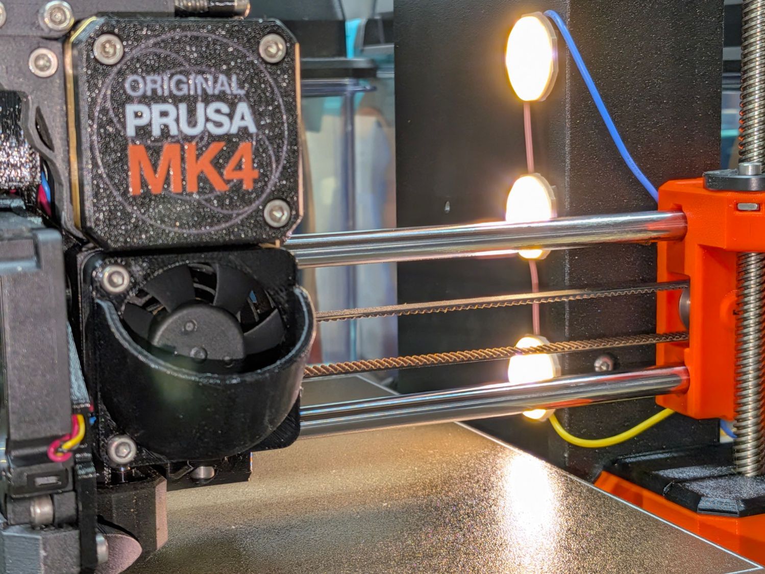
There’s very little clearance between the machine frame and the X Axis carriage on the threaded rod. Putting the LEDs in a 3D printed case and routing the wires lower on the column would be nice touches:
Prusa MK4 – Extruder sidelight – front view
The panels start at 30 mA when cold and drop to 25 mA as they warm up in the 63 °F = 17 °C Basement Shop. Each panel dissipates 250 mW: bright enough for the task, dim enough to avoid overpowering the camera’s limited dynamic range, and definitely within whatever power rating they should have.
Looking over the camera’s shoulder in normal shop lighting suggests it’s about right:
Although you’d want to set that up to run automagically when the RPi starts up, for now I just fire it off as needed through an SSH session, with the ampersand letting it run after that terminal session closes.
The RTSP port (5886) and stream (wrens) can be anything you like, which comes in handy when squirting streams through port-forwarded firewall pinholes using a router that cannot handle different external and internal port numbers.
While setting up a Raspberry Pi camera, I had occasion to pull out its USB power cable, whereupon grabbing the camera while unscrewing it from the tripod felt unusually sharp:
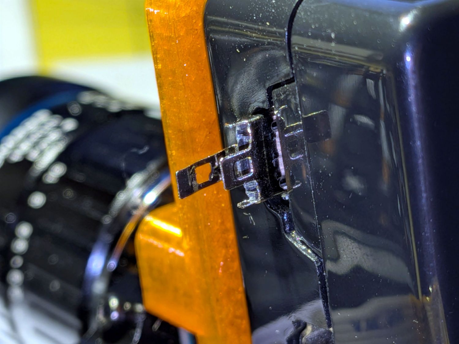
Micro-B USB – RPi jack
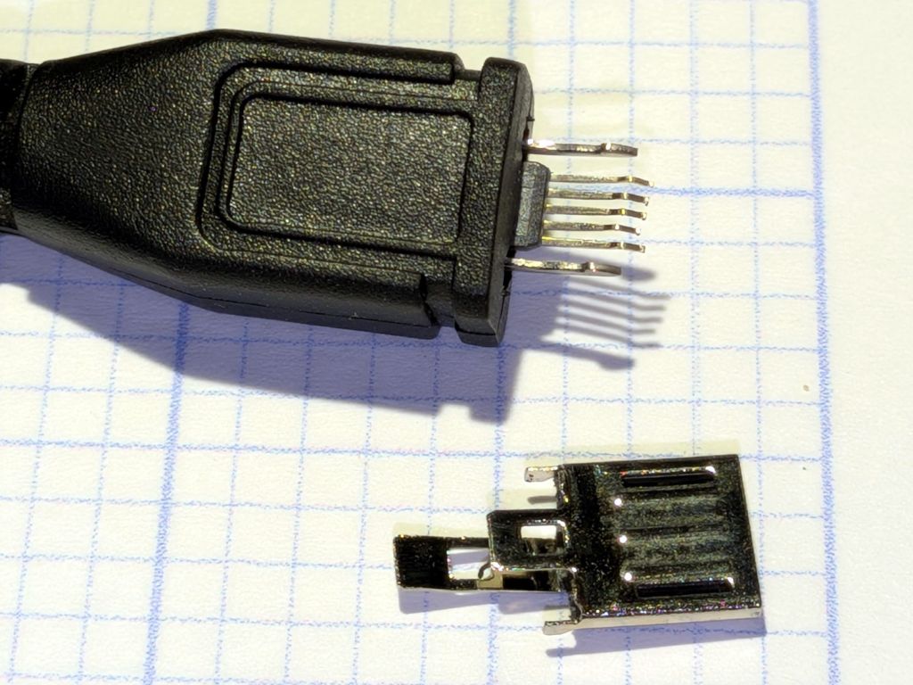
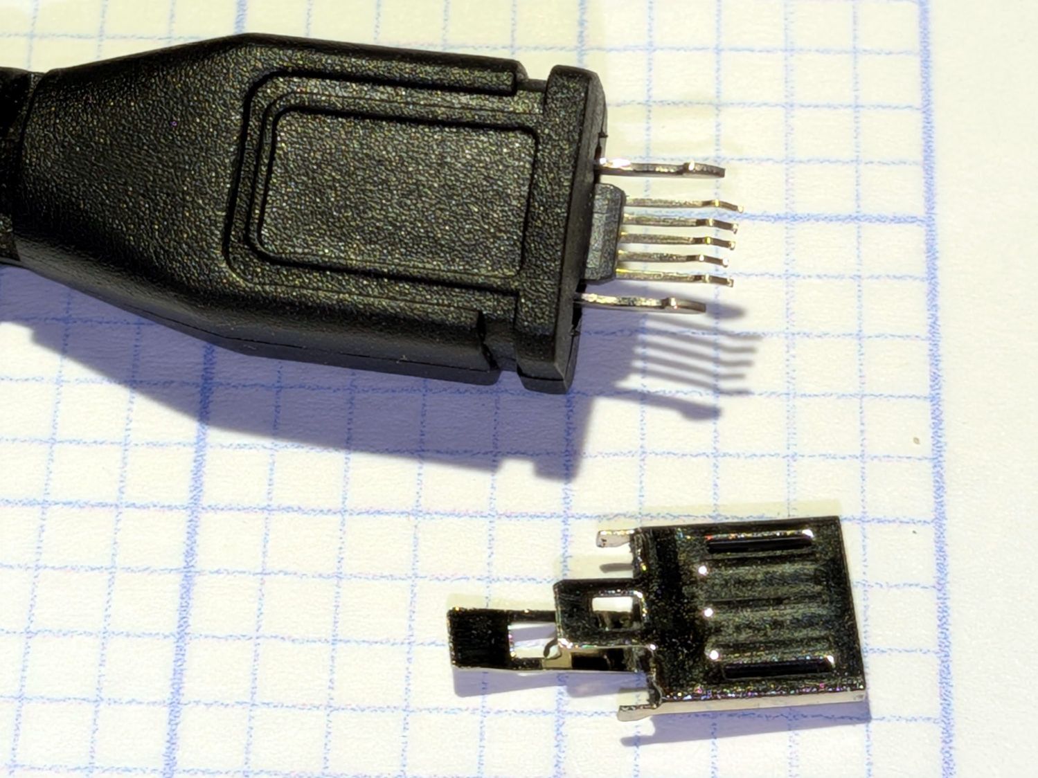
It seems the wall wart’s USB Micro-B connector pulled apart:
Micro-B USB connector – disembowled
Somewhat to my surprise, it was a CanaKit 5 V 2.5 A wall wart, definitely not the cheapest piece of junk ever made by the hand of man. On the other paw, it’s been around for quite a while, so …
Even I will agree that’s not a repairable failure, so I planned to splice in a Micro-B connector from a volunteer chosen from the Box o’ USB Micro-B Cables:
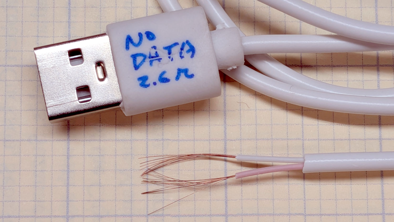
Each of those conductors appears to be made up of nine springy copper-colored 0.06 mm strands, somewhat smaller than 40 AWG: not what you want on the business end of a 2.5 A wall wart. I had previously measured the cable’s overall resistance with a surprisingly useful Treedix USB Cable Tester and it was on the very high end of the charge-only cable collection.
So I soldered a female USB-A breakout from the Drawer o’ USB Breakouts to the wall wart’s wires, snapped a 3D printed case around it, got a good (0.26 Ω) A-to-Micro-B cable from the Box o’ USB Adapters, and moved on.