Ed Nisley's Blog: Shop notes, electronics, firmware, machinery, 3D printing, laser cuttery, and curiosities. Contents: 100% human thinking, 0% AI slop.
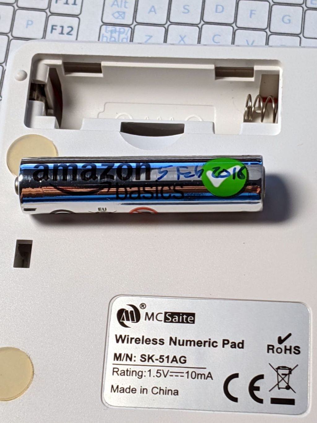
One of the streaming media players behaved funny, which always results in a numeric keypad battery replacement. This AmazonBasics AAA alkaline was down to about 0.5 V and long past its best-used-by date:
Suggestions that Amazon monitors their Marketplace sellers to figure out what’s profitable, then promote a Good Enough house brand product to kill off the competition, seem to describe the situation just about perfectly.
The iPhone was nowhere to be found, so harvesting its organs seemed appropriate:
Alpatronix iPhone XS case – opened
I assume the four steel disks aligned the coil with the wireless charger.
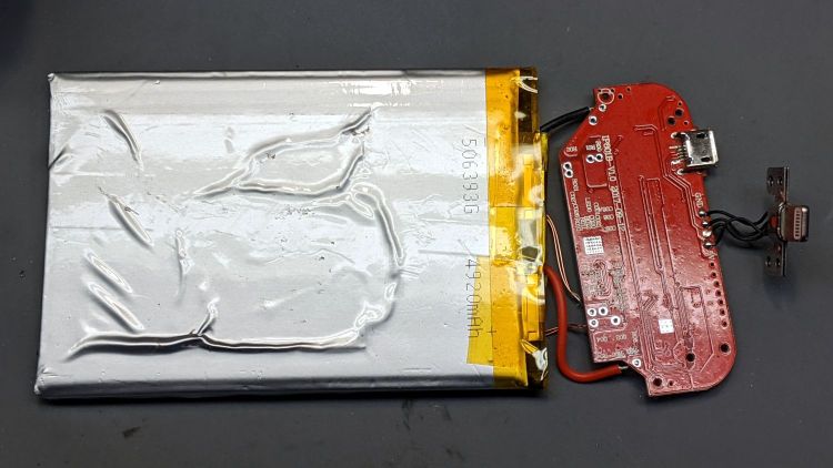
A few hours of steady tension relieved enough of the sticky tape to release the battery:
Alpatronix iPhone XS case – battery removal
Although its bag now sports a few wrinkles:
Alpatronix iPhone XS case – battery adhesion
The alert reader will note the outside of case proudly proclaimed “Capacity: 5000 mAh” while the underside of the battery says “4920 mAh”, but that’s surely close enough for consumer electronics these days.
The battery charges through either the Qi coil or a (mercifully standard Micro-B) USB jack and everything seems to work.
Not sure what I’ll do with a bare lithium cell and its charger, but they ought to come in handy for something around here.
For completeness, all of the surviving UPS sealed lead-acid batteries compared with a new battery:
UPS SLA 2021-10-22
They’re all discharged at 4 A, far higher than the nominal “20 hour” rate of 450 mA = 9 A·hr / 20 hr, but an order of magnitude closer to the rated UPS output of a few hundred watts which would call for a few tens of amps.
The new battery delivers 73 W·hr under those conditions, perhaps 50% more than the 50-ish W·hr from the used batteries, and with a much higher overall terminal voltage during the discharge.
Having just replaced Rev 1 of the amber running light with Rev 3 (about which, more later) on Mary’s Tour Easy, both the front and rear lights began blinking erratically. Given that they have completely independent circuitry, this strongly suggests a power problem.
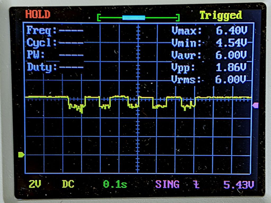
Herewith, the headlight circuit voltage:
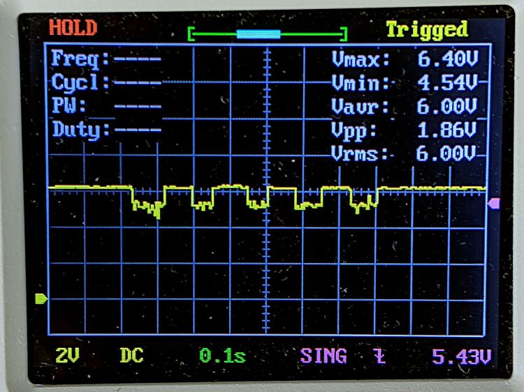
Bafang headlight voltage – two 1 W running lights
The voltage should be a constant 6 or 6.3 V, depending on which description you most recently read. That is the case with only one light attached, so the problem occurs only when running both lights.
The four pulses come from the amber LED’s Morse code “b” (dah-dit-dit-dit) with a 85 ms dits; the first dah pulse should be three times longer than the dits and definitely isn’t. The rear light’s red LED stays on continuously, except for two dark dits, so it draws a constant current and does not produce any changes in this trace.
Both lights have 2.0 Ω sense resistors setting the LED current to 400 mA, which corresponds to 250 mA each from the Bafang controller’s 6.3 V headlight circuit. The headlight circuit’s total of 500 mA should work fine, although the “spec” seems to be basically whatever the OEM headlight requires.
The Rev 1 amber light ran the LED at 360 mA with a supply current around 450 mA. That light and the rear light on the back ran fine, so the supply seems to have a hard maximum current limit at (a bit less than?) 500 mA.
The least-awful solution seems to be backing off both LED currents to 360 mA to keep the total supply current well under 500 mA.
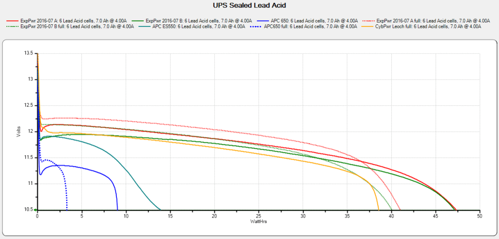
The UPS coddling the M2 printer began complaining about a bad battery, so I ran (nearly) all the UPS batteries through the tester:
UPS SLA 2021-10-10
The two blue flubs in the lower left come from the failed battery, with the dotted trace after charging to 13.7 V and letting the current drop to 20 mA.
The red and green traces come from two other UPS batteries installed in 2016, with the dotted traces after charging similarly. The orange-ish trace is from the battery in a Cyberpower UPS bought in 2016, so it looks like all batteries of that vintage fade equally.
Except for another pair of batteries in another UPS that had discharged stone cold dead; it may have been shut down and unplugged during a power outage and they never quite recovered.
After five years, it’s time to refresh the fleet …
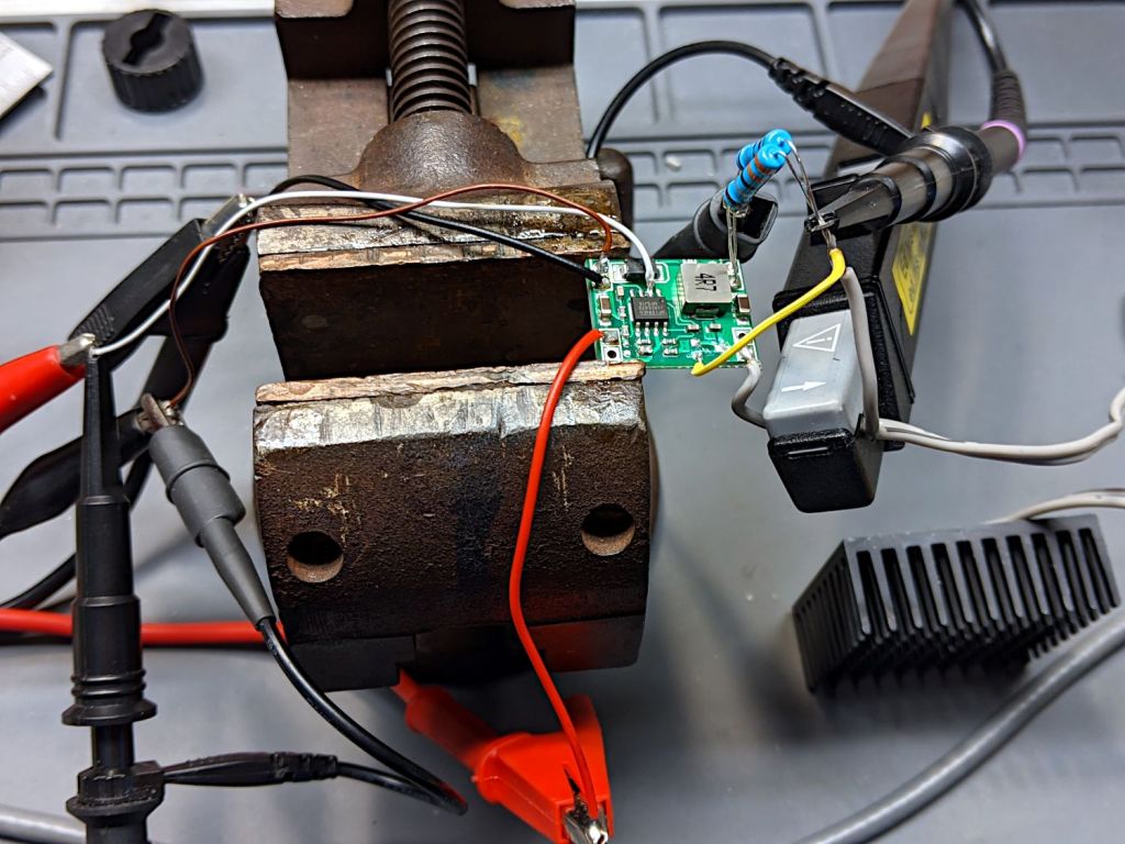
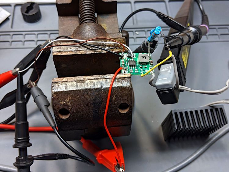
A test setup on the bench allows a bit more room for probes:
1 W Amber LED – MP1584 pulse setup
Some heatsink tape holds the LED to the far side of that oversize heatsink.
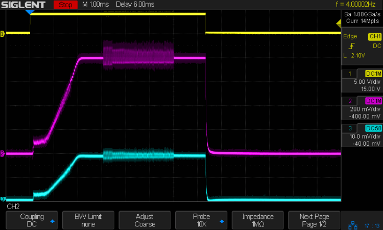
The input signal (top trace) arrives from a function generator set to blip the MP1584 regulator’s Enable input at 4 Hz with a 7 ms pulse:
Amber 1 w LED – pulse 200 mA-div
The purple trace is the voltage across the 2 Ω sense resistor. The MP1584 datasheet says the regulator soft-starts for (typically) 1.5 ms, during which the output ramps upward at 600 mV/ms to 800 mV , whereupon the actual regulation commences. The amber LED forward drop adds 2.5 V to the sense voltage, so the regulator produces 3.3 V from the 6.3 V bench supply input.
The cyan trace is the output current through the LED and sense resistor, also ramping up to 800 mV/2 Ω = 400 mA to drive the LED at 1 W.
The furry section shows when the regulator is actively regulating, with the output voltage rising and falling over a small range to maintain the average current (via the sense voltage). Successive Enable pulses may have longer, shorter, or completely missing fur, with no predictable pattern. Increasing the duty cycle doesn’t affect the results, with the fur sometimes extending for the entire pulse and sometimes being completely missing.
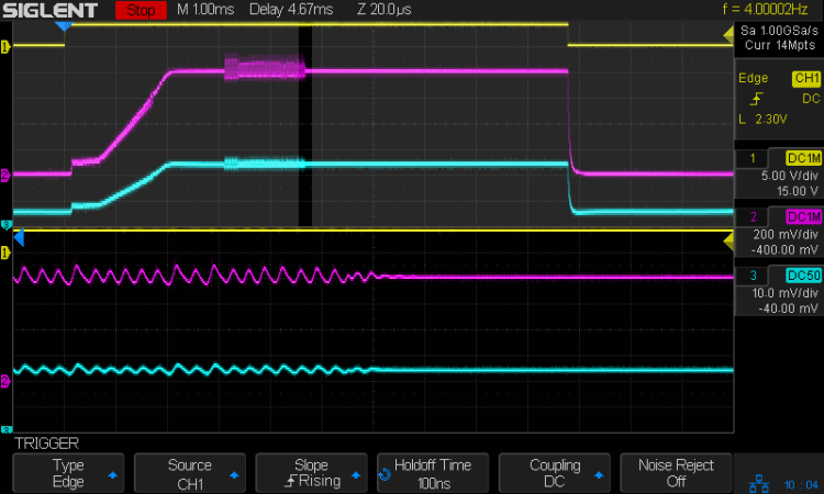
I think the regulator can settle in one of two metastable states. The best case has a constant voltage producing a constant LED current, with the sense voltage remaining within whatever deadband keeps the error amplifier happy. When something knocks the sense voltage out of the deadband, the error amp starts the usual regulation cycle, which will stop when the minimum or maximum voltage of a cycle remains within the deadband:
Amber 1 w LED – pulse – detail – 200 mA-div
The ripple shows the regulator running at three cycles per 20 µs division = 150 kHz, far lower then the MP1584 datasheet’s maximum 1.5 MHz and the typical 500 kHz in the test circuits. Perhaps a low frequency lets the designers use a cheap PCB and not worry about pesky EMI issues.
In any event, during this pulse the ripple amplitude gradually decreased as the output voltage settled at the point where the error voltage variation stayed within the deadband. The typical amp gain is only 200 V/V, so it’s definitely less fussy than something build around an op amp.
For whatever it’s worth, a 7 ms flash from a 1 W amber LED at 4 Hz is way attention-getting in a dim Basement Laboratory. You wouldn’t need an Arduino to produce that signal, even though I like the Morse capability.
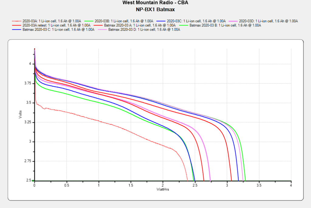
The Sony HDR-AX30V helmet camera puts far more demands on its battery than the Planet Bike Superflash:
Batmax NP-BX1 – 2021-09 vs 2020-03
The four traces on the right show the BatMax NP-BX1 lithium batteries (cells, really) originally stored about 3 W·h when they arrived in March 2020. The four solid traces to their left show the capacity dropped to a little over 2 W·h after two riding seasons. Batteries B and C started out above average and are now below, for whatever that means.
The red dotted trace shows the effect of not using the NP-BX1 test holder for that length of time; those homebrew contact pins apparently needed some exercise.