Ed Nisley's Blog: Shop notes, electronics, firmware, machinery, 3D printing, laser cuttery, and curiosities. Contents: 100% human thinking, 0% AI slop.
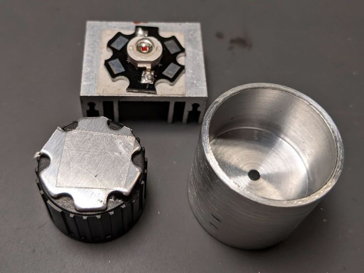
A pleasant evening at a virtual Squidwrench meeting produced the raw shape of the front end from a 1 inch aluminum rod:
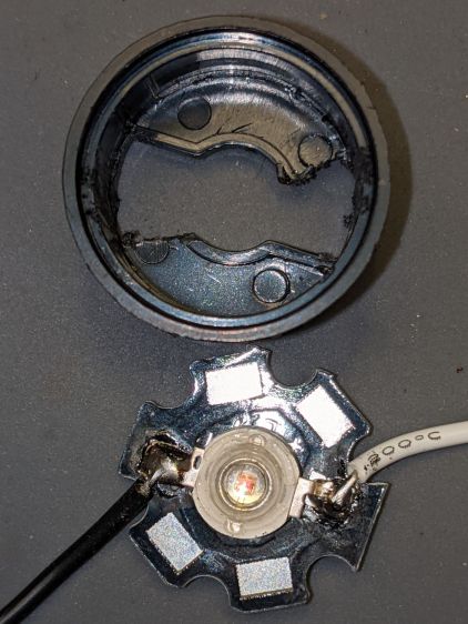
1 W LED Running Light – heatsink raw
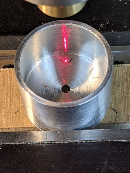
Trace the outline of the LED’s PCB inside the cylinder just for comfort, align to the center, and drill two holes with a little bit of clearance:
1 W LED Running Light – heatsink drilling
For the 24 AWG silicone wire I used, a pair of 2 mm holes 8.75 mm out from the center suffice:
1 W LED Running Light – heatsink fit
Gnaw some wire clearance in the lens holder:
1 W LED Running Light – wiring
Tap the central hole for an M3×0.5 screw, which may come in handy to pull the entire affair together.
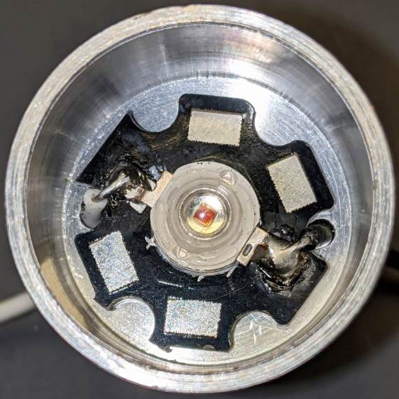
Epoxy the PCB onto the heatsink with the lens holder keeping it aligned in the middle:
1 W LED Running Light – heatsink clamp
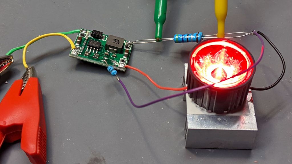
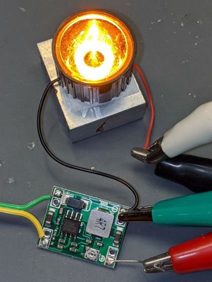
Then see how hot it gets dissipating 900 mW with 360 mA of current from a 2.2 Ω resistor:
1 W LED Running Light – heatsink test
As you might expect, it gets uncomfortably warm sitting on the bench, so it lacks surface area. The first pass will use a PVC cylinder for easy machining, but a full aluminum shell would eventually be a nice touch.
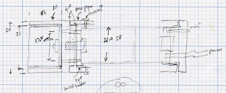
A doodle with some dimensions and aspirational features:
Running Light – 1 W LED case doodle
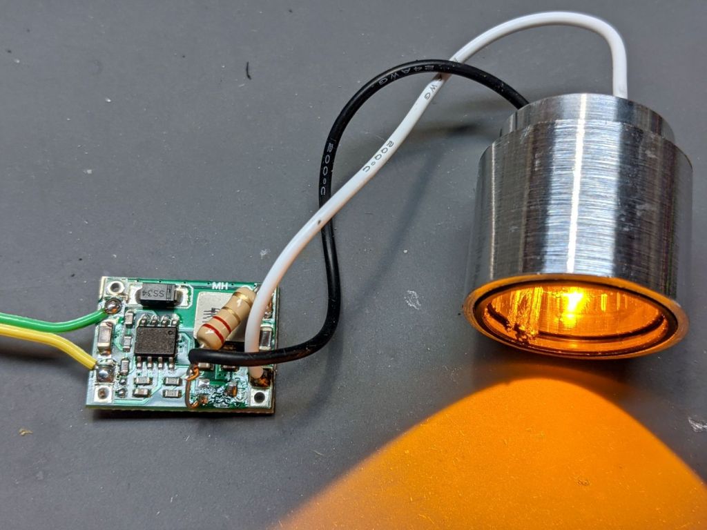
Even without a lens and blinkiness, it’s attention-getting!
Mostly because I wanted to verify that it really worked:
MP1584 current – red LED – Arduino blinkiness
The Arduino Nano runs the default Blink program that all the knockoff manufacturers use as their final QC test.
The MP1584 specs say the Enable input can accept a logic signal up to 6 V, the Nano runs at 5 V regulated down from the 6.3 V from the bench supply, and the 1 W red LED now flashes 1 s ON / 1 s OFF.
The current feedback works as it did before, too, which is comforting.
The Nano adds 20 mA to the bench supply, so the whole affair runs at 220 mA = 1.4 W. Of course, it’s now at a 50% duty cycle, so that helps.
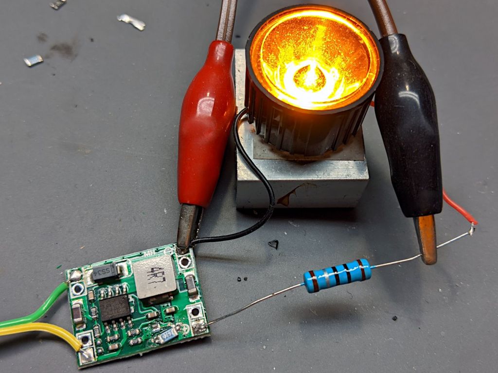
MP1584 buck regulator – current feedback – red LED
I started with the same 1.65 Ω sense resistor and got the same 484 mA current, with the LED forward drop at a surprisingly high 3.3 V = 1.6 W. Ouch.
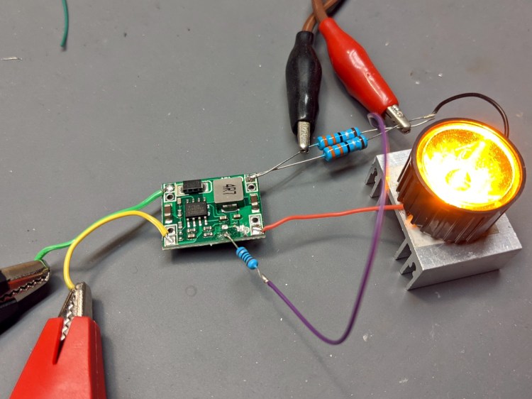
Adding a 1 Ω series resistor to get 2.65 Ω lowered the current to 300 mA with a forward drop of 2.45 V = 740 mW.
Running the numbers suggested a 2.3 Ω sense resistor made from a pair of parallel 4.7 Ω resistors, which produced 346 mA and an LED drop of 2.66 V = 920 mW. The resistor dissipates 280 mW.
The bench supply provides 6.3 V @ 200 mA = 1.26 W, so the overall efficiency is 94% and the LED burns 73% of the input.
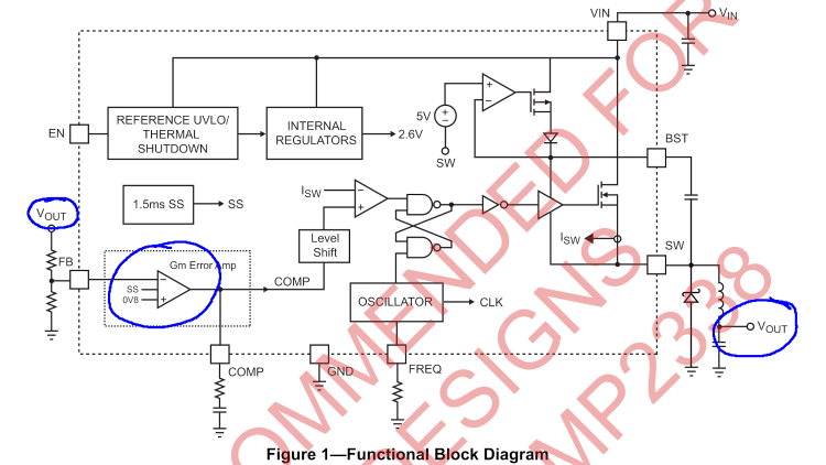
The PCB is the generic MP1584 buck regulator, as seen before in its normal voltage feedback mode, rewired to get feedback based on the LED current, so that it adjusts the output voltage to maintain a constant LED current, regardless of LED forward drop variations.
Pin 4 normally sees the output voltage divided down to the 0.8 V error comparator reference voltage:
MP1584 – buck regulator – voltage feedback
Yes, the MP1584 is “not recommended for new designs”, which surely accounts for the myriad cheap regulators built around it. Somebody picked up a great deal on a vast pile of obsolete ICs and is passing the savings along to us; there are exactly zero hits for MP2338 buck regulators.
Putting the ballast resistor on the low side of the LED turns it into a current sensor:
MP1584 – buck regulator – LED current feedback
Pick R to drop 0.8 V at the desired LED current and It Just Works™.
The two 3.3 Ω resistors in the top photo produce a 1.65 Ω sense resistor to set the LED current at:
485 mA = 800 mV / 1.65 Ω
It actually works out to a bit higher than that, because I stuck a 100 Ω resistor in series with the feedback input. The PCB still has the 8.2 kΩ resistor from the original voltage divider, so the error amp sees only 99% of the sense voltage, but it’s close enough.
With 6.3 V and 0.28 A = 1.76 W from the bench supply over on the left, the regulator puts 490 mA through the LED. The LED drops 2.54 V = 1.24 W and the resistor drops 0.809 V (that 1% thing) = 0.4 W for a total of 3.35 V and 1.64 W. The regulator is 93% efficient, although the resistor burns a quarter of the energy.
One could use a Hall effect current sensor and an op amp circuit to deliver the proper feedback voltage without resistive loss, but I think burning half a watt is Good Enough for the purpose.
One could add parallel resistors with MOSFET switches to set the LED current. An unswitched resistor would set the lowest current, with switched parallel resistors lowering the resistance, raising the current, and brightening the LED.
The PCB leaves the Enable input floating with an internal pullup. Grounding the pin shuts off the LED as you’d expect, so I can blink the LED without any further hassle.
One could imagine simultaneously blinking and brightening the LED as needed.
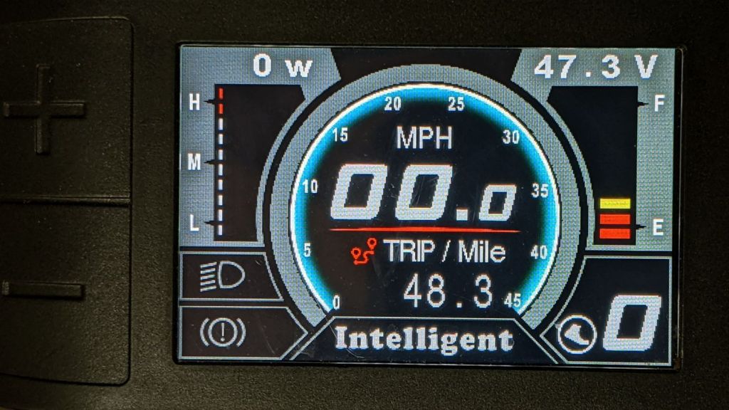
After a few days of riding, the Bafang 500C display on Mary’s bike gives the battery status:
Bafang 500C display – 48 mi 30 pct
The thermometer scale on the right shows 30% remaining battery capacity after 48.3 miles of riding, with the 11.6 A·h battery at 47.3 V.
For our type of riding, each 10% increment of battery charge delivers about 7 miles of range. Although we could probably get 70 miles between charges, recharging the battery at 20 to 30% makes more sense; the bike is in the garage, so why not?
Our typical 10 to 15 mile rides now average 12+ mph, with some level sections ticking along at 18 mph (giving me some serious exercise), which isn’t much by pro rider standards.
Computing the lithium battery charge state by measuring its voltage isn’t particularly accurate, but it’s about as good as you’re going to get.
Based on simpleminded testing, a 1 W amber LED drops about 2.5 V at 430 mA. A 1 Ω ballast resistor drops another half volt and burns a quarter of a watt, sufficient to cover some LED forward drop variation.
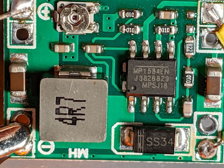
The trimpot is entirely too twitchy, so I replaced it with an SMD resistor:
Amber 1W LED – fixed voltage SMD
The trimpot read 26.5 kΩ after I extracted it, but I surely nudged it a smidgen in the process.
For the record (first column is SMD topmark, second is measured resistance):
3012 = 29.9 kΩ (!!) → 3.67 V into a 100 Ω resistor
2492 = 24.9 kΩ → 3.19 V : 2.63 V @ 550 mA = 1.45 W
2362 = 22.6 kΩ → 2.97 V : 2.52 V @ 450 mA = 1.13 W
223 = 22.0 kΩ → 2.91 V : 2.484 V @ 425 mA = 1.06 W
With 6.3 V @ 210 mA = 1.3 W from the bench regulator, the resistor now burns 180 mW at 425 mA and the LED burns 82% of the input power.
Letting it cook overnight settled out with the LED at 2.47 V and 440 mA = 1.09 W, with 6.3 V at 220 mA = 1.4 W from the bench supply. The LED dissipates 78% of the input power and the resistor burns 190 mW = 14%, so the regulator uses 120 mW = 8%.
I can come close to the final output voltage by plugging the new resistor value and the 8.2 kΩ resistor (on the PCB) into the MP1584 datasheet equations, but figuring the resistor to get a specific output voltage seems largely empirical.
Not counting the heatsink, you’re looking at less than three bucks of parts; living in the future is great.
Fitting the lens over the LED produces a shatteringly bright beam, at least in the Basement Laboratory:
Amber 1W LED – lens test
The lens has a conical cavity surrounding the LED lens to capture the light and redirect it to the beam forming reflector. It’s done with total internal reflection, there are no coatings, and it’s a wonder to behold: one-shot molded aspheric optics at work.
Not seating the lens firmly against the LED produces a dark spot in the middle of the beam. I soldered the leads directly to the LED and cut out the sides of the black lens holder, as soldering them to the convenient side pads would prevent the lens from seating properly.
The headlight output is good for 6-ish V and 3 W = 500-ish mA, so burning half the power in a simple dropping resistor or linear current regulator is a Bad Idea™. You can get constant current LED drivers, but apparently not with 6 V input and 1 W output, so stepping the voltage down makes more sense. You’d want at least a little ballast resistor in there to soak up small forward drop changes with temperature variations.
The regulator can handle up to 28 V input and the tiny trimpot must cover nearly that range of output voltages, so the 2.5 V output jams it near the minimum end of its rotation (which is, of course, backwards). This calls for a fixed resistor to eliminate the effects of vibration on a trimpot at 10% of its range.