The Smell of Molten Projects in the Morning

Ed Nisley's Blog: Shop notes, electronics, firmware, machinery, 3D printing, laser cuttery, and curiosities. Contents: 100% human thinking, 0% AI slop.

Category: Electronics Workbench

Electrical & Electronic gadgets

  • CO₂ Laser Tube Current: Constant Power

    CO₂ Laser Tube Current: Constant Power

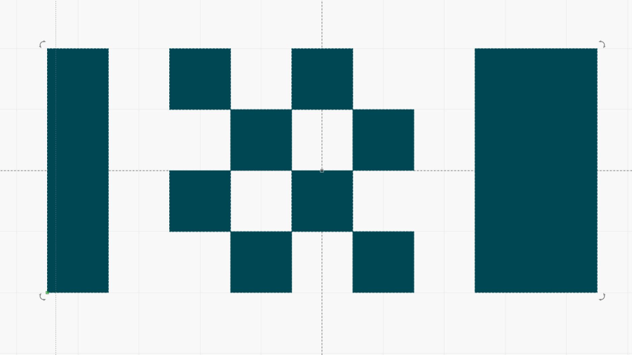
    The test pattern consists of 1 mm blocks:

    Pulse Timing Pattern - 1 mm blocks
    Pulse Timing Pattern – 1 mm blocks

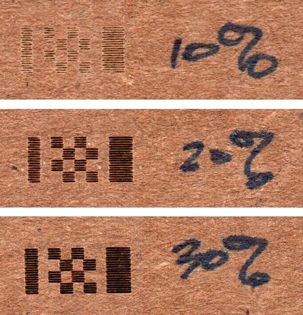
    I set the layer speed at 250 mm/s = 4 ms / mm, then set PWM (a.k.a. “power”) for each test, and measured the results, which look like this for three power levels on corrugated cardboard:

    Pulse Timing Pattern - cardboard - 10 20 30 pct
    Pulse Timing Pattern – cardboard – 10 20 30 pct

    The scan interval of 0.2 mm produces distinct lines at 10% PWM, the lower limit of the laser’s range. The lines remain separate at 30%, although their width is definitely increasing.

    Yesterday’s post explains the test wiring setup and the signals in the scope screenshots.

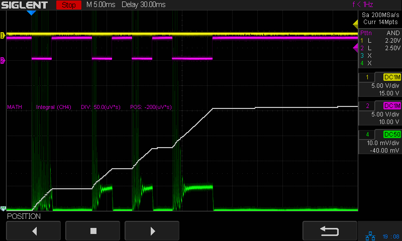
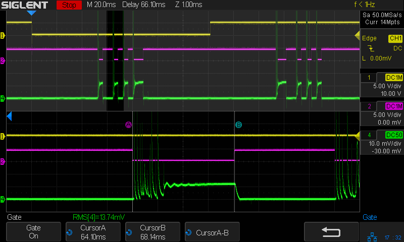
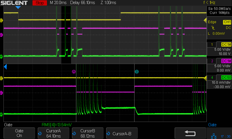
    The 10% PWM current waveform looks like nothing you’d expect:

    Tube Current - 10pct - 250mm-s - 5ma-div
    Tube Current – 10pct – 250mm-s – 5ma-div

    The scope triggers at the start of a left-to-right scan line, with 50 ms devoted to ramping up the speed to 250 mm/s before the start of the vertical bar along the left edge and slowing down before reversing.

    The green trace shows huge spikes in the laser current, not a well-defined DC current pulse, and they’re offscale beyond 30 mA at 5 mA/div. The baseline sits well above the 0 V line due to the AM502 amplifier’s breathtaking thermal drift; I occasionally touch it up, but the current really is zero between the pulses.

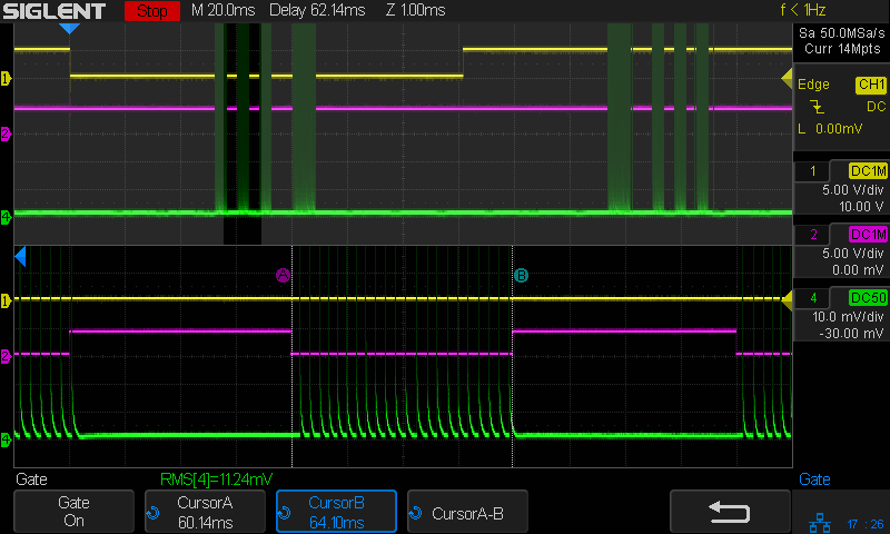
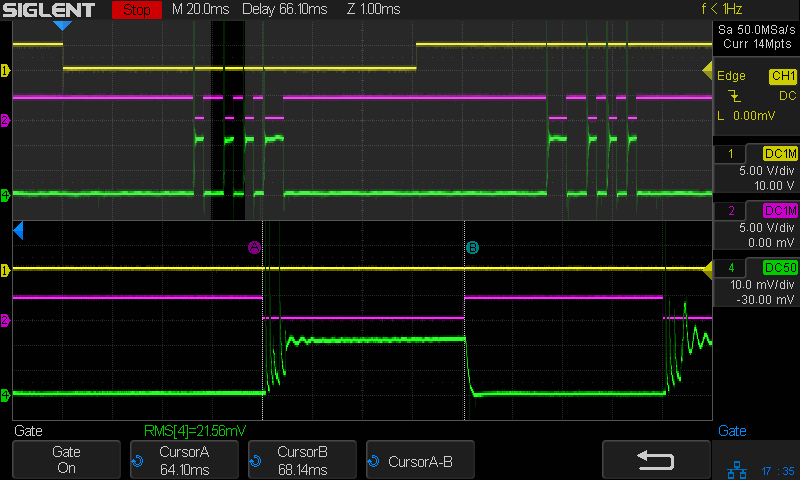
    Similarly for 20% PWM:

    Tube Current - 20pct - 250mm-s - 5ma-div
    Tube Current – 20pct – 250mm-s – 5ma-div

    Even through there’s little visible difference between the 10% and 20% current waveforms, there’s a distinct difference in the actual beam power delivered to the cardboard.

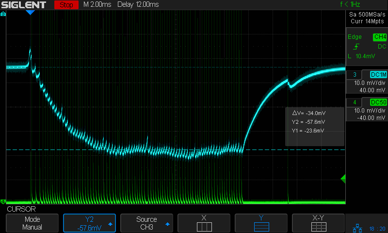
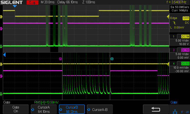
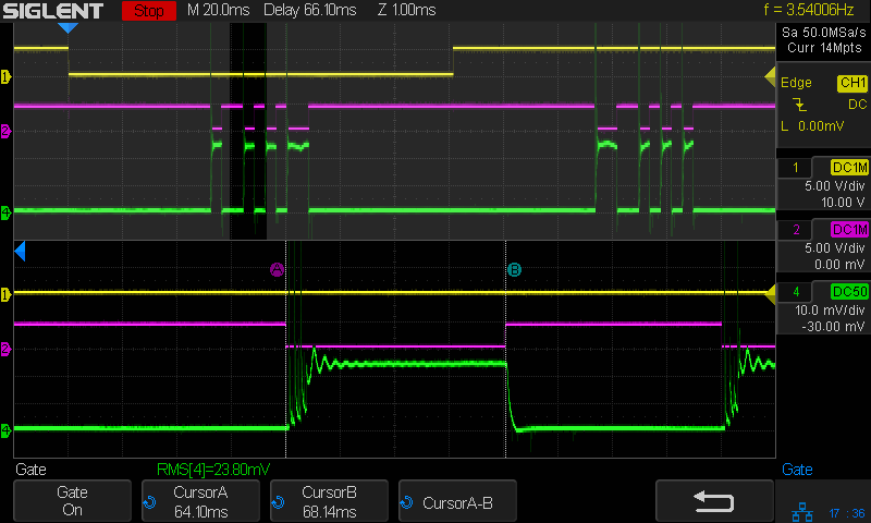
    At 30% PWM the beam current looks a bit more reasonable:

    Tube Current - 30pct - 250mm-s - 5ma-div
    Tube Current – 30pct – 250mm-s – 5ma-div

    The 2 mm = 8 ms bar on the right gives the current time to stabilize at 6 mA, but all of the pulses have at least 3 ms of spikes. The first pulse definitely looks worse, so it seems the power supply gets better as the scan line progresses.

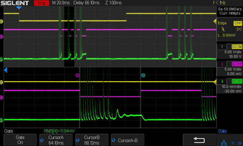
    At 40% PWM the beam current pulses look more like pulses:

    Tube Current - 40pct - 250mm-s - 5ma-div
    Tube Current – 40pct – 250mm-s – 5ma-div

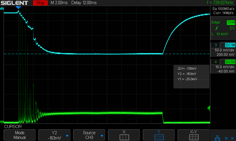
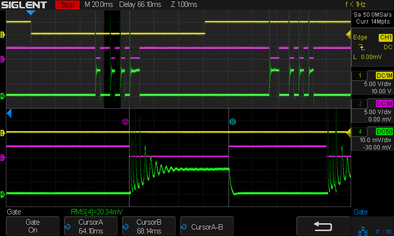
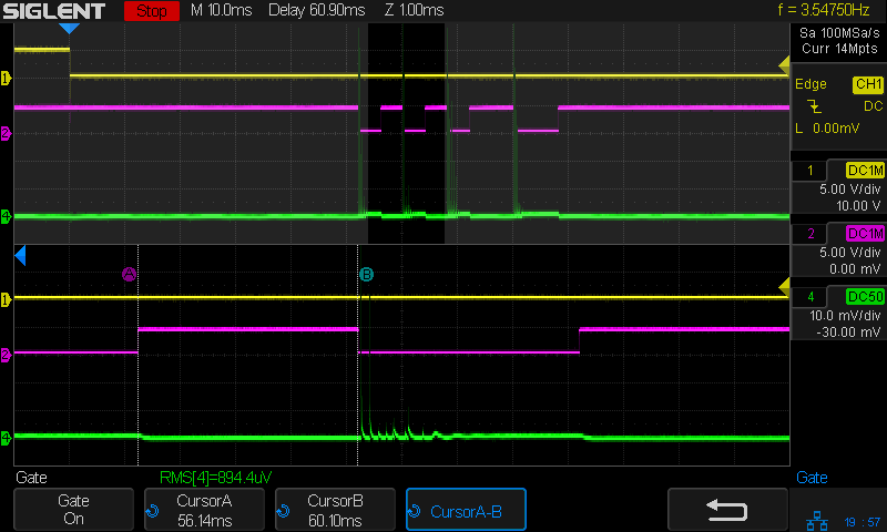
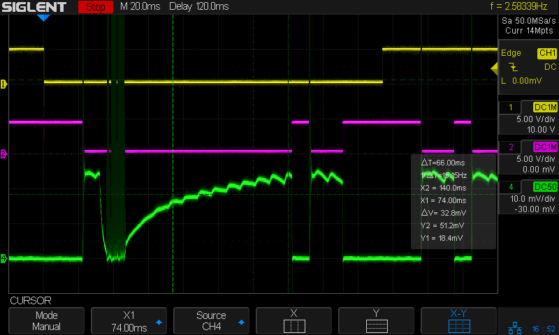
    They still have 3 ms or so of those startup spikes, as seen in this closer look at the first pulse in a line, scaled at 10 mA/div (along with the PWM drive signal):

    Tube Current - 40pct PWM first detail - 250mm-s - 10ma-div
    Tube Current – 40pct PWM first detail – 250mm-s – 10ma-div

    The top of those spikes exceed 70 mA!

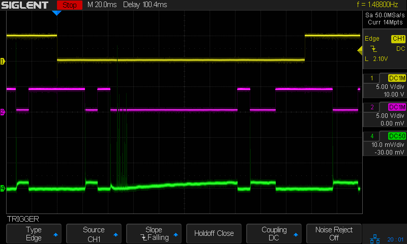
    At 80% PWM, the current waveform looks like a damped tank circuit:

    Tube Current - 80pct first - 250mm-s - 5ma-div
    Tube Current – 80pct first – 250mm-s – 5ma-div

    The 20 mA at the end of that pulse suggests the maximum tube current would be 25 mA, which is undoubtedly why OMTech recommends running at no more than 70% PWM = 17-ish mA.

    The pulses start immediately after the L-ON signal goes active and stop promptly when it goes inactive, so there’s no question about the responsiveness. What baffles me is why the current looks the way it does.

    I must figure out how to have the scope compute the RMS value of those spikes, with a sufficiently large mA/div setting to keep the entire range of the pulses on the screen.

  • CO₂ Laser Tube Current: Test Wiring

    CO₂ Laser Tube Current: Test Wiring

    Having seen some rather bizarre laser tube current waveforms from the replacement power supply (and an equivalent Cloudray supply I bought as a backup) in the OMTech 60 W laser, I finally got A Round Tuit for a closer look.

    I tapped three signals from the Ruida KT332N controller by the simple expedient of crunching wires into the output terminal clamps along with their original ferrules:

    KT332N controller - Tube Current test connections
    KT332N controller – Tube Current test connections

    From top to bottom:

    • X axis DIR: low = left-to-right motion = toward X+
    • Laser L-ON: low-active laser beam enable
    • PWM: pulse-width modulation laser power control

    Those three cables pass through a small hole in the cabinet to the left of the hatch on their way to channels 1, 2, and 3 of the scope.

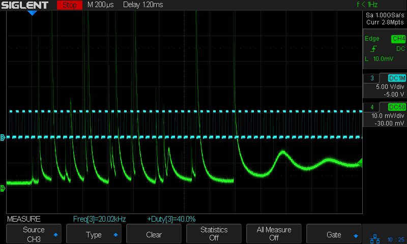
    The PWM signal (cyan, channel 3) isn’t particularly useful, but a quick look confirmed it is an active-high signal ticking along at 20 kHz, with a duty cycle corresponding to the selected laser “power”:

    Tube Current - 40pct PWM first detail - 250mm-s - 10ma-div
    Tube Current – 40pct PWM first detail – 250mm-s – 10ma-div

    The bottom trace (green, channel 4) is the laser tube current, as monitored by a Tek A6302 Hall-effect current probe around the tube’s cathode (low voltage return) lead:

    HV laser power supply - current probe setup
    HV laser power supply – current probe setup

    This time around, I poked a bight of that overly long wire through the hole in the cabinet (just above the power-line earth ground terminal) so I could keep the probe outside the cabinet and close the hatch.

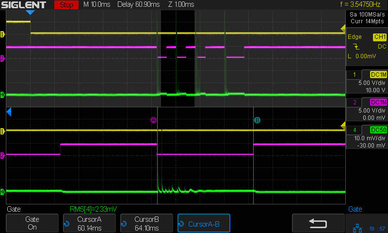
    Minus the PWM signal, the scope looks like this:

    Tube Current - 40pct - 250mm-s - 5ma-div
    Tube Current – 40pct – 250mm-s – 5ma-div

    The top trace (yellow, channel 1) is the DIR signal, with a high-to-low transition triggering the scope when the X axis begins moving from left to right.

    The second trace (magenta, channel 2) is the L-ON laser enable; the high-voltage power supply drives current through the laser tube only when L-ON is low.

    The third trace (green, channel 4) is, as above, the laser tube current. The Tek AM502 amplifier sets the gain, with the scope channel always set to 10 mV/div with a 50 Ω input impedance, so I must put the current scale in the screenshot file name (which becomes the caption here).

    With all that in mind, the next few posts will make more sense … and I can remember what I did.

  • Laser Cutter: Improving the Red-Dot Pointer

    Laser Cutter: Improving the Red-Dot Pointer

    The red-dot pointer on the OMTech laser cutter has the same problem as my laser aligner for the Sherline mill: too much brightness creating too large a visual spot. In addition, there’s no way to make fine positioning adjustments, because the whole mechanical assembly is just a pivot.

    The first pass involved sticking a polarizing filter on the existing mount while I considered the problem:

    OMTech red dot pointer - polarizing filter installed
    OMTech red dot pointer – polarizing filter installed

    The red dot pointer module is 8 mm OD and the ring is 10 mm ID, but you will be unsurprised to know the laser arrived with the module jammed in the mount with a simple screw. Shortly thereafter, I turned the white Delrin bushing on the lathe to stabilize the pointer and installed a proper setscrew, but it’s obviously impossible to make delicate adjustments with that setup.

    Making the polarizing filter involves cutting three circles:

    OMTech red dot pointer - polarizing filter
    OMTech red dot pointer – polarizing filter

    Rotating the laser module in the bushing verified that I could reduce the red dot to a mere shadow of its former self, but it was no easier to align.

    Replacing the Delrin bushing with a 3D printed adjuster gets closer to the goal:

    Pointer fine adjuster - solid model
    Pointer fine adjuster – solid model

    Shoving a polarizing filter disk to the bottom of the recess, rotating the laser module for least brightness, then jamming the module in place produces a low-brightness laser spot.

    The 8 mm recess for the laser module is tilted 2.5° with respect to the Y axis, so (in principle) rotating the adjuster + module (using the wide grip ring) will move the red dot in a circle:

    Improved red-dot pointer - overview
    Improved red-dot pointer – overview

    The dot sits about 100 mm away at the main laser focal point, so the circle will be about 10 mm in diameter. In practice, the whole affair is so sloppy you get what you get, but at least it’s more easily adjusted.

    The M4 bolt clamping the holder to the main laser tube now goes through a Delrin bushing. I drilled out the original 4 mm screw hole to 6 mm to provide room for the bushing:

    Improved red-dot pointer - drilling bolt hole
    Improved red-dot pointer – drilling bolt hole

    The bushing has a wide flange to soak up the excess space in the clamp ring:

    Improved red-dot pointer - turning clamp bushing
    Improved red-dot pointer – turning clamp bushing

    With all that in place, the dimmer dot is visually about 0.3 mm in diameter:

    Improved red-dot pointer - offset
    Improved red-dot pointer – offset

    The crappy image quality comes from excessive digital zoom. The visible dot on the MDF surface is slightly larger than the blown-out white area in the image.

    The CO₂ laser hole is offset from the red laser spot by about 0.3 mm in both X and Y. Eyeballometrically, the hole falls within the (dimmed) spot diameter, so this is as good as it gets. I have no idea how durable the alignment will be, but it feels sturdier than it started.

    Because the red dot beam is 25° off vertical, every millimeter of vertical misalignment (due to non-flat surfaces, warping, whatever) shifts the red dot position half a millimeter in the XY plane. You can get a beam combiner to collimate the red dot with the main beam axis, but putting more optical elements in the beam path seems like a Bad Idea™ in general.

    The OpenSCAD source code as a GitHub Gist:

    // Laser cutter red-dot module fine adjust
    // Ed Nisley KE4ZNU 2022-09-22
    Layout = "Show"; // [Build, Show]
    /* [Hidden] */
    ThreadThick = 0.25;
    ThreadWidth = 0.40;
    HoleWindage = 0.2;
    Protrusion = 0.1; // make holes end cleanly
    inch = 25.4;
    ID = 0;
    OD = 1;
    LENGTH = 2;
    function IntegerMultiple(Size,Unit) = Unit * ceil(Size / Unit);
    //———————-
    // Dimensions
    PointerOD = 8.0 + 0.2; // plus loose turning fit
    Aperture = 5.0; // clear space for lens
    SkewAngle = 2.5;
    MountRing = [10.0,16.0,8.0]; // OEM laser module holder
    GripRim = [Aperture,MountRing[OD] + 2*1.5,3.0]; // finger grip around OD
    NumSides = 24;
    //———————-
    // Useful routines
    module PolyCyl(Dia,Height,ForceSides=0) { // based on nophead's polyholes
    Sides = (ForceSides != 0) ? ForceSides : (ceil(Dia) + 2);
    FixDia = Dia / cos(180/Sides);
    cylinder(r=(FixDia + HoleWindage)/2,
    h=Height,
    $fn=Sides);
    }
    //———————-
    // Holder geometry
    module Holder() {
    difference() {
    union() {
    cylinder(d=GripRim[OD],h=GripRim[LENGTH],$fn=NumSides);
    PolyCyl(MountRing[ID],MountRing[LENGTH] + GripRim[LENGTH],NumSides);
    }
    translate([0,0,-Protrusion]) // close enough without skew angle
    PolyCyl(Aperture,2*MountRing[LENGTH],NumSides);
    translate([0,0,MountRing[LENGTH]/2 + GripRim[LENGTH]])
    rotate([0,SkewAngle,0])
    translate([0,0,-MountRing[LENGTH]/2])
    PolyCyl(PointerOD,2*MountRing[LENGTH],NumSides);
    }
    }
    //———————-
    // Build it
    if (Layout == "Show") {
    Holder();
    }
    if (Layout == "Build") {
    Holder();
    }

  • SJCAM M20: Another Battery Bites the Dust

    SJCAM M20: Another Battery Bites the Dust

    A little more than two years after replacing its internal battery, the SJCAM M20 camera on my Tour Easy once again wouldn’t last to the end of the driveway if I forgot to turn on the external battery pack. This time around, the camera was so firmly jammed in the printed seat frame mount that I had to cut the mount apart.

    Yup, that puppy is all swoll up:

    SJCAM M20 swollen battery - side view
    SJCAM M20 swollen battery – side view

    Poor thing looks like a tiny pillow:

    SJCAM M20 swollen battery - pouch
    SJCAM M20 swollen battery – pouch

    While I had it apart, I tried to clean / refurbish the button contacts on the top. Unfortunately, they’re pretty well buried in the camera frame and I was unwilling to dismantle the optics, remove the display, and gut the camera to find out if they were more accessible from the back surface:

    SJCAM M20 - switch internals
    SJCAM M20 – switch internals

    While all that was going on, I ran off a new mount in white PETG:

    SJCAM M20 - white case installed
    SJCAM M20 – white case installed

    I’m down to the last battery. The “4.35V” on the pillow indicates they’re special high-voltage lithium-polymer cells, so I can’t just drop a random lithium pouch cell in there and expect it to Just Work.

    I think the “782633” is the cell size, so, if I were willing to have a few thousand on the shelf, a 552525 pouch might fit. The reduced capacity wouldn’t be a problem, as it must just keep the camera’s clock ticking between rides.

    Drat!

  • OMTech 60W Laser: Repurposing the HV Power Supply Water Protect Input

    OMTech 60W Laser: Repurposing the HV Power Supply Water Protect Input

    For reference, the input terminals on the OMTech anonymous 60 W HV laser power supply:

    OMTech 60W HV power supply - terminals
    OMTech 60W HV power supply – terminals

    AFAICT, that’s the default layout for all similar power supplies.

    The H and L pins are the High- and Low-active enable inputs that, when it’s working right, control the laser output. The KT332 controller (and, most likely, all RuiDa controllers) produce a low-active output, so you just wire the controller’s output to the L input and you’re done.

    That was the original failure that got me to this point: the power supply ignored its L input and turned the beam on at whatever power the PWM signal on the IN terminal called for. Having that happen was surprising, having it happen with the cabinet lid open was … disturbing.

    The P input is intended for the Water Protect signal from the flow sensor on the laser cooling plumbing. When the water is flowing, the IN terminal will be low and the power supply will pay attention to the L input.

    The power supply arrived with a jumper between the P input and the G ground / common terminal:

    OMTech 60W HV power supply - Water Protect jumper
    OMTech 60W HV power supply – Water Protect jumper

    The jumper holds the P input low = active, meaning the power supply thinks the water is always flowing.

    It turns out that the Water Protect signal goes only to the controller. When it’s inactive = no water flowing, the controller will refuse to fire the laser and also sound an alarm. Running the signal directly to the power supply would result in a puzzling failure-to-fire with no diagnostic from the controller.

    I removed that jumper and added a (green) wire from the Lid Interlock signal at the controller:

    OMTech KT332 controller - Lid Interlock input - added wire
    OMTech KT332 controller – Lid Interlock input – added wire

    To the power supply’s P input:

    OMTech 60W HV power supply - Water Protect as Lid Interlock
    OMTech 60W HV power supply – Water Protect as Lid Interlock

    In principle, if this power supply fails the same way as the previous one (with its L input always active), then at least it won’t fire with the lid up.

    Believing that may display a childish naivety, but at least the thing seems marginally safer than it was before.

  • Discrete LM3909: Drain ‘Em Dry

    Discrete LM3909: Drain ‘Em Dry

    Given that I put them into a gadget intended to use partially dead alkaline cells, the “05” date on the cells, and that it’s been blinking since last November, I cannot complain when this happens:

    Discrete LM3907 - leaky Duracells - as found
    Discrete LM3907 – leaky Duracells – as found

    I might just fill the battery holder with vinegar and let it fizz for a while:

    Discrete LM3907 - leaky Duracells - corrosion traces
    Discrete LM3907 – leaky Duracells – corrosion traces

    Even my simple discrete LM3909 circuit can blink a blue LED from a battery producing under 1 V, but those cells were flat dead. Gotta look over there more often, I suppose.

  • Newmowa NP-BX1: Video Duration vs Charge

    Newmowa NP-BX1: Video Duration vs Charge

    Having run the Newmowa NP-BX1 batteries through my old Sony HDR-AS30V helmet camera a few times, a plot seemed in order:

    Newmowa NP-BX1 video duration vs charge
    Newmowa NP-BX1 video duration vs charge

    The cluster of dots shows most of our rides last about an hour.

    The line is an eyeballometrical fit, slightly coerced to pass through the origin because that’s where it should go.

    The 9.1 mA·hr/min slope is in reasonable agreement with past results, given different batteries and charger. The Keweisi meter emerged first from the box.

    Straining the hr/min dimensional nonsense out of the slope suggests the camera averages 550 mA and 1.9 W. Derating those by a few percent to account for the recharge efficiency might be in order, but they’re surely in the right ballpark.