The original HV power supply in the OMTech 60 W laser went casters-up just barely inside OMTech’s six month tube-and-supply warranty period. For the record, the laser controller reports this status info since mid-March:
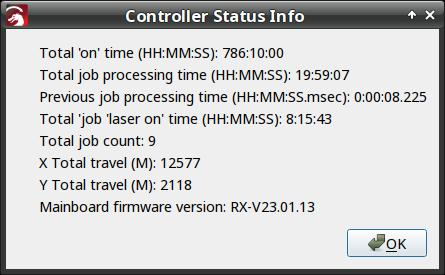
I think the Total job laser on time line says the power supply failed after firing the laser for a little over eight hours. The OMTech manual says the laser tube should last 1000 to 2000 hours (low vs high power), which suggests I should stock up on power supplies.
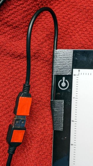
Its replacement just arrived:
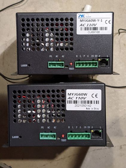
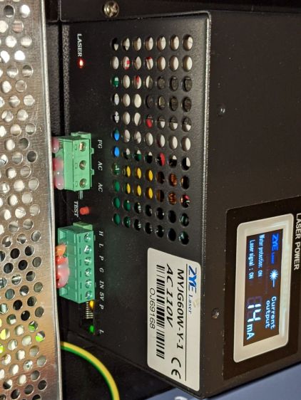
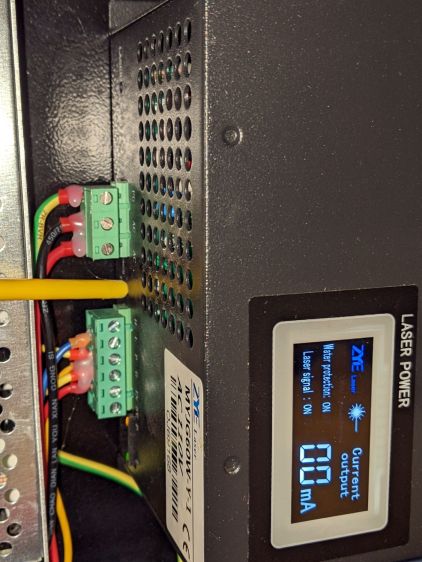
It (bottom) seems to be a knockoff of the original ZYE Laser supply (top), with a similar model number and a “serial number” resembling a date from last year. All the connectors matched up, which isn’t too surprising.
The three most interesting inputs:
L= controller’s active-lowL-ONenable outputIN= controller’sPWMoutputP= jumper toG(circuit ground) — not water flow sensor
Also note the two AC power-line terminals directly adjacent to the TEST button, then consider insulation and stand-off distances before poking the button with your index finger.
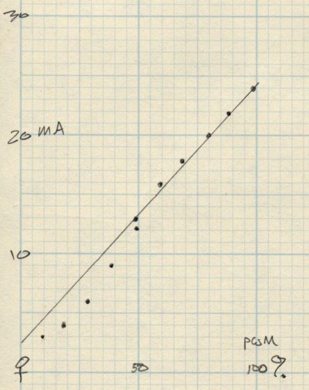
The power supply has a digital current meter, so I plotted output current against PWM input:
Taking more points at the low end, with vertical bars indicating single-digit flicker on the meter:
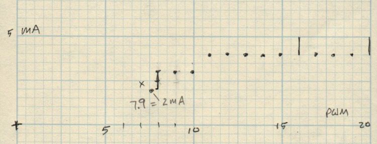
I have little reason to believe the meter reading indicates the true current with any accuracy and I know CO₂ laser output power does not scale linearly with the current.
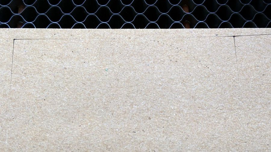
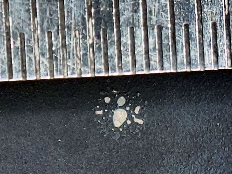
But it’s cutting again, which is a step in the right direction.