Because I want to measure several fairly high temperatures in and around the extruder with the LinuxCNC controller for the M2, I need a multi-channel thermocouple input. LinuxCNC’s hal_input interface module exposes the values produced by USB HID peripherals as HAL pins, which seems to be a nice way to add devices. A bit of searching revealed the TC4 Arduino Shield four-channel thermocouple + four-channel thermistor + assorted I/O board produced by the homeroasters.org folks as part of their DIY coffee roast controller.
The gotcha: ordinary Arduino boards cannot (without extraordinary effort) become USB HID peripherals, as their USB interface works only as a serial data device. The solution: the new-ish Arduino Leonardo has an on-chip USB interface that can act as a USB HID peripheral as well as the usual serial device.
Dan Newman, of Sailfish firmware fame, conjured up an a Arduino program (which, IMO, is far more complex than a mere sketch) that provides both a human-readable terminal interface and a LinuxCNC HAL-compatible USB HID interface using the Leonardo’s USB capabilities; the TC4Server project repository is on my GitHub account to keep it close to all the other stuff that should appear over the course of this project. His firmware builds on the libraries for the homeroaster’s tc4-shield Google Code project, but is intended for use with LinuxCNC, rather than as part of an Arduino controller.
It’s worth noting that the Leonardo has a mere 32 kB of program storage, so the extensive help documentation built into the program helped prevent feature creep.
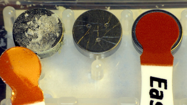
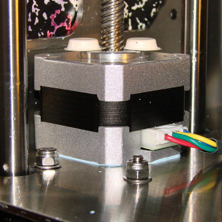
Although I’m not yet using LinuxCNC with the M2, I can use TC4-Server’s serial terminal interface to read four channels of thermocouple data to help figure out what’s going on with the M2’s extruder thermistor. The TC4 shield has screw terminals for the thermocouples, but I also added a Proto ScrewShield board for thermistor resistors and easier connections:

The TC4 Shield PCB layout assumes it’s being used with the original Arduino series of boards that bring the I2C (aka I2C, IIC, etc) SDA and SCL signals out on the A4 and A5 analog input pins, respectively. The newer Leonardo board brings SDA and SCL out in a separate header, so you must hotwire them across the board. The green and blue wires (stripped from a ribbon cable) accomplish that purpose: they’re plugged into the new Leonardo header through bent male header pins and clamped into the ScrewShield terminals. This assumes the Leonardo’s A4 and A5 pins remain as inputs, which is true for Dan’s firmware. If you actually need those pins for analog inputs, then you must remove the header pins that interconnect the boards and hotwire directly to the TC4 headers.
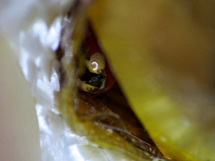
The TC4 shield includes an on-board temperature sensor that serves as the thermocouple cold-junction compensation reference. In my simple tests, the board has about 1 °C of self-heating, so I also use it to report the ambient temperature.
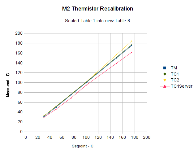
With all that in hand, I connected the thermocouple epoxied to the M2’s nozzle to the TC4 and re-ran the previous test with the modified thermistor table:
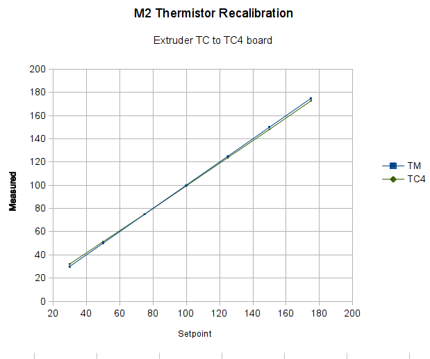
The TC4 shield produces the same result as the Fluke meter with the same thermocouple, so we know those results will be consistent.
The modified thermistor table produces results that overlay thermocouple data. The questions come down to the accuracy of the thermocouple and whether bending the thermistor table actually represents an inherent property of the thermistor or just compensates for another problem.
Part of my motivation for using thermocouples, rather than thermistors, is that thermocouples avoid the whole dance of matching a given thermistor with a set of properties. Given the uncertain provenance of most thermistors, I have no reason to believe any of them match their alleged datasheets…