Ed Nisley's Blog: Shop notes, electronics, firmware, machinery, 3D printing, laser cuttery, and curiosities. Contents: 100% human thinking, 0% AI slop.
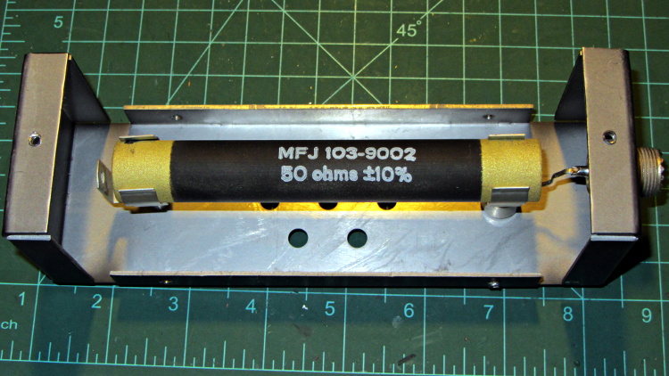
If you happen to own an MFJ-260B dummy load and it’s giving you weird SWR values, take the cover off and roll the power resistor in its mounting clips:
MFJ-260B HF Dummy Load – power resistor
My buddy Aitch discovered that oxide / corrosion / dirt buildup between the resistor and the clips can produce absolutely baffling results, even while passing enough current to warm up the element, far more power than you’d think would burn away any crud.
A box of surplus Vexta NEMA 23 stepper motors arrived:
Vexta C6925-9212K stepper motors
The data plate sayeth:
Model C6925-9212K
2 phase
1.8°/step
2.3 V
3 A
According to Dan, who happened into the deal, that Vexta model number applies to their custom motors, which accounts for the fact that there’s no further data available anywhere.
Dividing 2.3 V by 3 A = 0.77 Ω windings. Multiplying 2.3 V by 2 A suggests a 7 W maximum dissipation.
Poking around with a meter identifies the windings:
Blue – White – Red
Green – Yellow – Black
Given those colors, the Y G B W R K color sequence on the connector doesn’t make any sense to me. Most likely, there’s a standard I’m unaware of.
The resistance from the center taps outward measures 1.0 Ω, which is close enough to 0.8 Ω for me. Measuring across the whole winding gives 1.8 Ω.
The inductance is 1.0 mH from the center tap and 4.0 mH across the whole winding. Remember that inductance varies as the square of the number of turns.
The time constant for a complete winding = 2.5 ms = 4 mH / 1.6 Ω.
Adding a strip of white LEDs under the X stage helps shed some light on events atop the M2’s build platform; this was very nearly the first improvement after getting the printer, but somehow I’ve never written down where that nice white glow comes from.
This view shows the strip from below, looking up from the -Y direction in front of the stage:
White LED strip under X axis frame
I originally screwed the wires into the terminals from the hulking 12 V Dell laptop brick for the platform heater, but then I had to unscrew the wires whenever I moved the M2 and I didn’t like sharing the connectors with those huge conductors. Now the LEDs are in parallel with the extruder fan (which runs continuously), sharing the FAN1 screw terminals inside the electronics case.
The M2 firmware uses PWM to cut the 19.5 V supply from a much smaller laptop brick down to roughly 12 V RMS for the fans, but that isn’t such a Good Thing for LEDs. The strip has 120 Ω resistors that drop about 2.4 V at 20 mA from a 12 V supply, leaving 9.6 V for the LEDs (at about 3.2 V each). Running from 19.5 V means the resistors will see about 9.5 V and pass nearly 80 mA, four times the nominal rating, during each PWM pulse.
Based on those measurements, the light output doesn’t go up by nearly a factor of four during each pulse.
I plan to add a 12 V supply to the LinuxCNC box, probably by recycling the 12 V brick from the M2, which will get the LED current back down to a reasonable level. With any luck, they’ll survive this mistreatment and not carry a grudge.
You could, of course, just power the LEDs from a separate 12 V wall wart, but that adds Yet Another Thing when I carry the M2 to demos.
A simple test of additional insulation below the Makergear M2’s heated build platform, measuring the time required to heat the platform from 30 °C to 80 °C:
As-shipped without insulation: 8:20
Cardboard + cotton cloth: 8:30
Cardboard + aluminum foil + cotton: 8:00
That’s with a resolution of about 10 seconds and 1 °C. Ambient temperature was 25 °C; I preheated the platform to 30 °C for a repeatable starting point. The heater was full-on for the entire time and I tried to record the time until it first turned off at the setpoint temperature.
So my initial insulation didn’t make any difference; ten seconds (in the wrong direction!) seems down in the noise.
Adding aluminum improved the situation, but not by much.
The platform wasn’t moving, so there’s no air circulation on either surface. I think it will be possible to record / plot the platform heater duty cycle during printing using LinuxCNC’s HAL components, so some useful data should emerge from that.
I think the bottom line is that there’s so much heat transfer up through the glass plate and away that reducing the heat flow from the bottom by a little bit doesn’t matter…
Having recently kibitzed on a project using de-icing cables (with some success) to soften PVC pipe for bending, herewith the useful numbers.
Data printed on the original cable:
100 ft length
120 VAC
800 W
Derived values:
6.7 A = 800 W / 120 V
8 W/ft = 800 W / 100 ft
1.2 V/ft = 120 V / 100 ft
18 Ω = (120 V)2 / 800 W
180 mΩ/ft = 18 Ω / 100 ft
The starting point was a 62 ft length of the cable, as I’d long ago converted the end into a heated bed for starting plants early in the spring. That presented a resistance of 11 Ω, drew a current of 11 A, and dissipated 1.3 kW at 21 W/ft. A kilowatt-class dimmer handled the load, but adjoining sections of the cable got hot enough to melt the insulation and terminate the experiment.
A shorter length of cable might be suitable for a cheap laptop brick power supply. To keep the dissipation under, say, 10 W/ft, we have:
7.5 A = sqrt( 10 W/ft / 180 mΩ/ft )
1.3 V/ft = 7.5 A * 180 mΩ/ft
The Dell D220P-01 brick on the M2 provides 12 V at 18 A (!) and costs under $20 on eBay:
9 ft = 12 V / 1.3 V/ft
90 W = 12 V * 7.5 A
1.6 Ω = 9 ft * 180 mΩ/ft
You could run two 9 ft lengths cables in parallel from the same hulking brick. Whether that’s enough to soften a length of PVC pipe from the inside, without having the insulation get all melty, that’s another question…
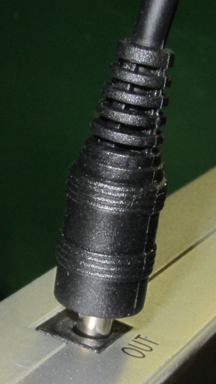
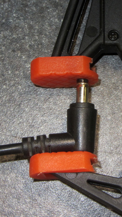
Rather than cutting the pack apart, I buttered up the end of an intact plug with some ABS solvent glue (a hellish homebrew mixture of acetone and MEK), rammed it into the socket, and held it in place for a minute:
LiIon Pack – undamaged plug insertion
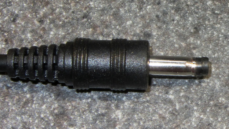
The tip emerged on the first try:
LiIon Pack – rescued plug tip joined
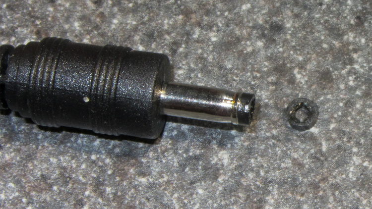
Even better, it cracked off the plug without too much effort:
LiIon Pack – rescued plug tip separated
More solvent glue and a few hours of clamping worked fine:
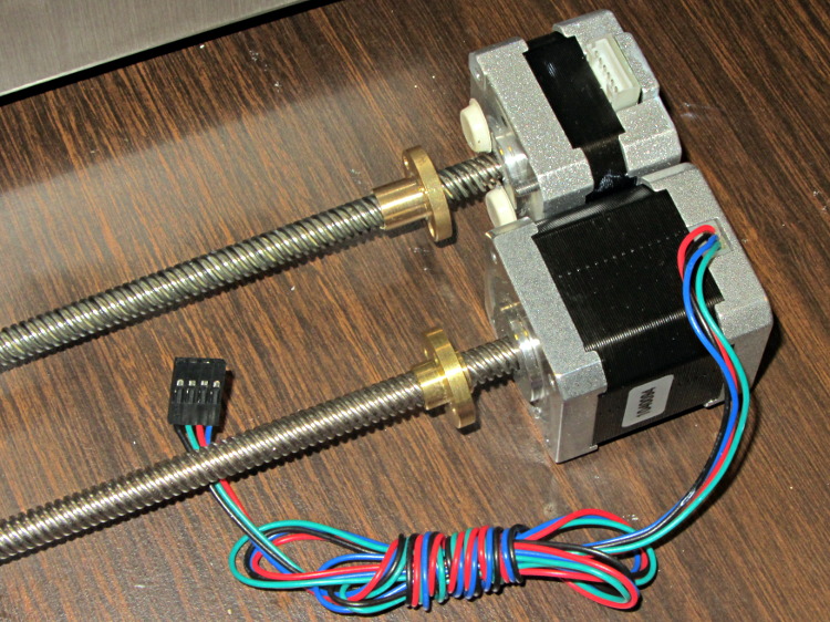
Dan sent me a Kysan 17HD-B8X300-A, a leadscrew-equipped stepper motor with much higher torque than the Makergear Z axis motor. According to the Kysan description, which is all we have to go on: 4.2 V @ 1.5 A means 2.8 Ω, at which current it produces 5.5 kg·cm = 540 mN·m of torque. I measure 3.2 Ω and 3.5 mH, not that that makes much difference.
I worked out some of the numbers in that post and, if they’re close, then the new motor has twice the torque of the OEM one. What’s more important is that the new motor will work correctly with a microstepping drive and won’t bake while doing so.
The new motor has more metal to it than the old one:
M2 Z Axis motors – OEM vs replacement
The leadscrew follower nut has unthreaded holes, but, mercifully, has the same OD, fits nicely into the Z stage, and those four holes line up perfectly.
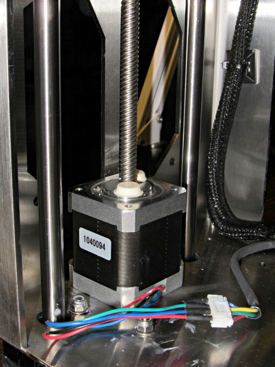
I chopped off most of the wires and spliced a JST plug onto the end; of course, the motor ran backwards. Having foreseen that eventuality, I had not shrunk the tubing over the wires: swap a pair, shrink the tubing, and it’s done:
M2 Z Axis motor replacement
Some notes from the operation:
Disconnect all the cables
Remove HBP + glass plate
Lay printer on +X side of the chassis
Remove screws holding Z motor to chassis
Remove nylock nuts and screws from leadscrew follower nut
Remove Z axis home switch
Run Z stage to top of rods
The leadscrew bearing will probably have fallen out by now
Loosen Z rod clamp nuts & bolts (top & bottom of rods)
Push Z rods out using a nut driver, pull with a rag for traction
Be ready to catch the Z stage when you remove the rods!
Angle motor & leadscrew out of the chassis
Angle new motor & leadscrew into the chassis
Reinstall everything in reverse order
Recalibrate everything…
The Z rod sliders have little balls inside, but they didn’t fall out during this adventure. I don’t know if that’s reliable information or not.